2002 DODGE RAM brake light
[x] Cancel search: brake lightPage 7 of 2255

FASTENER IDENTIFICATION
DESCRIPTION
The SAE bolt strength grades range from grade 2
to grade 8. The higher the grade number, the greater
the bolt strength. Identification is determined by the
line marks on the top of each bolt head. The actual
bolt strength grade corresponds to the number of line
marks plus 2. The most commonly used metric bolt
strength classes are 9.8 and 10.9. The metric
strength class identification number is imprinted on
the head of the bolt. The higher the class number,
the greater the bolt strength. Some metric nuts are
imprinted with a single-digit strength class on the
nut face. Refer to the Fastener Identification and
Fastener Strength Charts (Fig. 7) and (Fig. 8).
INTERNATIONAL SYMBOLS
1 High Beam 13 Rear Window Washer
2 Fog Lamps 14 Fuel
3 Headlamp, Parking Lamps, Panel Lamps 15 Engine Coolant Temperature
4 Turn Warning 16 Battery Charging Condition
5 Hazard Warning 17 Engine Oil
6 Windshield Washer 18 Seat Belt
7 Windshield Wiper 19 Brake Failure
8 Windshield Wiper and Washer 20 Parking Brake
9 Windscreen Demisting and Defrosting 21 Front Hood
10 Ventilating Fan 22 Rear hood (Decklid)
11 Rear Window Defogger 23 Horn
12 Rear Window Wiper 24 Lighter
6 INTRODUCTIONBR/BE
INTERNATIONAL VEHICLE CONTROL & DISPLAY SYMBOLS (Continued)
Page 37 of 2255
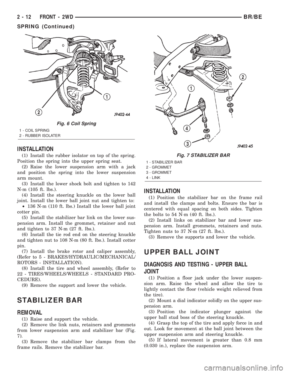
INSTALLATION
(1) Install the rubber isolator on top of the spring.
Position the spring into the upper spring seat.
(2) Raise the lower suspension arm with a jack
and position the spring into the lower suspension
arm mount.
(3) Install the lower shock bolt and tighten to 142
N´m (105 ft. lbs.).
(4) Install the steering knuckle on the lower ball
joint. Install the lower ball joint nut and tighten to:
²136 N´m (110 ft. lbs.) Install the lower ball joint
cotter pin.
(5) Install the stabilizer bar link on the lower sus-
pension arm. Install the grommet, retainer and nut
and tighten to 37 N´m (27 ft. lbs.).
(6) Install the tie rod end on the steering knuckle
and tighten nut to 108 N´m (80 ft. lbs.). Install cotter
pin.
(7) Install the brake rotor and caliper assembly,
(Refer to 5 - BRAKES/HYDRAULIC/MECHANICAL/
ROTORS - INSTALLATION).
(8) Install the tire and wheel assembly, (Refer to
22 - TIRES/WHEELS/WHEELS - STANDARD PRO-
CEDURE).
(9) Remove the support and lower the vehicle.
STABILIZER BAR
REMOVAL
(1) Raise and support the vehicle.
(2) Remove the link nuts, retainers and grommets
from lower suspension arm and stabilizer bar (Fig.
7).
(3) Remove the stabilizer bar clamps from the
frame rails. Remove the stabilizer bar.
INSTALLATION
(1) Position the stabilizer bar on the frame rail
and install the clamps and bolts. Ensure the bar is
centered with equal spacing on both sides. Tighten
the bolts to 54 N´m (40 ft. lbs.).
(2) Install links on stabilizer bar and lower sus-
pension arm. Install grommets, retainers and nuts.
Tighten nuts to 37 N´m (27 ft. lbs.).
(3) Remove the supports and lower the vehicle.
UPPER BALL JOINT
DIAGNOSIS AND TESTING - UPPER BALL
JOINT
(1) Position a floor jack under the lower suspen-
sion arm. Raise the wheel and allow the tire to
lightly contact the floor (vehicle weight relieved from
the tire).
(2) Mount a dial indicator solidly on the upper sus-
pension arm.
(3) Position the indicator plunger against the
upper ball stud boss of the steering knuckle.
(4) Grasp the top of the tire and apply force in and
out. Look for movement at the ball joint between the
upper suspension arm and steering knuckle.
(5) If lateral movement is greater than 0.8 mm
(0.030 in.), replace the suspension arm.
Fig. 6 Coil Spring
1 - COIL SPRING
2 - RUBBER ISOLATER
Fig. 7 STABILIZER BAR
1 - STABILIZER BAR
2 - GROMMET
3 - GROMMET
4 - LINK
2 - 12 FRONT - 2WDBR/BE
SPRING (Continued)
Page 90 of 2255
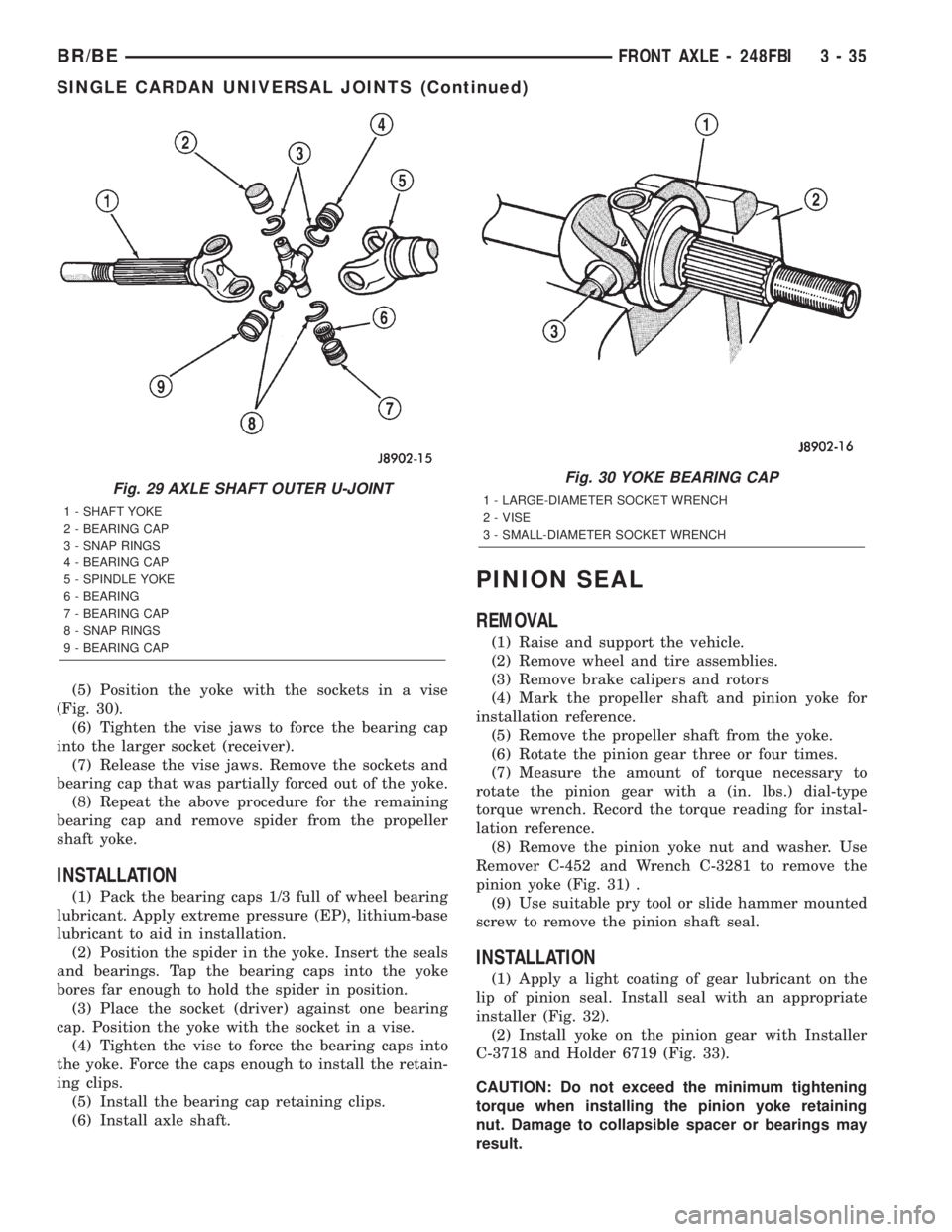
(5) Position the yoke with the sockets in a vise
(Fig. 30).
(6) Tighten the vise jaws to force the bearing cap
into the larger socket (receiver).
(7) Release the vise jaws. Remove the sockets and
bearing cap that was partially forced out of the yoke.
(8) Repeat the above procedure for the remaining
bearing cap and remove spider from the propeller
shaft yoke.
INSTALLATION
(1) Pack the bearing caps 1/3 full of wheel bearing
lubricant. Apply extreme pressure (EP), lithium-base
lubricant to aid in installation.
(2) Position the spider in the yoke. Insert the seals
and bearings. Tap the bearing caps into the yoke
bores far enough to hold the spider in position.
(3) Place the socket (driver) against one bearing
cap. Position the yoke with the socket in a vise.
(4) Tighten the vise to force the bearing caps into
the yoke. Force the caps enough to install the retain-
ing clips.
(5) Install the bearing cap retaining clips.
(6) Install axle shaft.
PINION SEAL
REMOVAL
(1) Raise and support the vehicle.
(2) Remove wheel and tire assemblies.
(3) Remove brake calipers and rotors
(4) Mark the propeller shaft and pinion yoke for
installation reference.
(5) Remove the propeller shaft from the yoke.
(6) Rotate the pinion gear three or four times.
(7) Measure the amount of torque necessary to
rotate the pinion gear with a (in. lbs.) dial-type
torque wrench. Record the torque reading for instal-
lation reference.
(8) Remove the pinion yoke nut and washer. Use
Remover C-452 and Wrench C-3281 to remove the
pinion yoke (Fig. 31) .
(9) Use suitable pry tool or slide hammer mounted
screw to remove the pinion shaft seal.
INSTALLATION
(1) Apply a light coating of gear lubricant on the
lip of pinion seal. Install seal with an appropriate
installer (Fig. 32).
(2) Install yoke on the pinion gear with Installer
C-3718 and Holder 6719 (Fig. 33).
CAUTION: Do not exceed the minimum tightening
torque when installing the pinion yoke retaining
nut. Damage to collapsible spacer or bearings may
result.
Fig. 29 AXLE SHAFT OUTER U-JOINT
1 - SHAFT YOKE
2 - BEARING CAP
3 - SNAP RINGS
4 - BEARING CAP
5 - SPINDLE YOKE
6 - BEARING
7 - BEARING CAP
8 - SNAP RINGS
9 - BEARING CAP
Fig. 30 YOKE BEARING CAP
1 - LARGE-DIAMETER SOCKET WRENCH
2 - VISE
3 - SMALL-DIAMETER SOCKET WRENCH
BR/BEFRONT AXLE - 248FBI 3 - 35
SINGLE CARDAN UNIVERSAL JOINTS (Continued)
Page 118 of 2255
PINION SEAL
REMOVAL
(1) Raise and support the vehicle.
(2) Mark universal joint, pinion yoke and shaft for
installation reference.
(3) Disconnect the propeller shaft from the pinion
yoke.
(4) Remove the wheel and tire assemblies.
(5) Remove brake calipers to prevent any drag
that may cause a false bearing preload torque mea-
surement.
(6) Rotate pinion yoke three or four times.
(7) Record pinion gear rotating torque with an
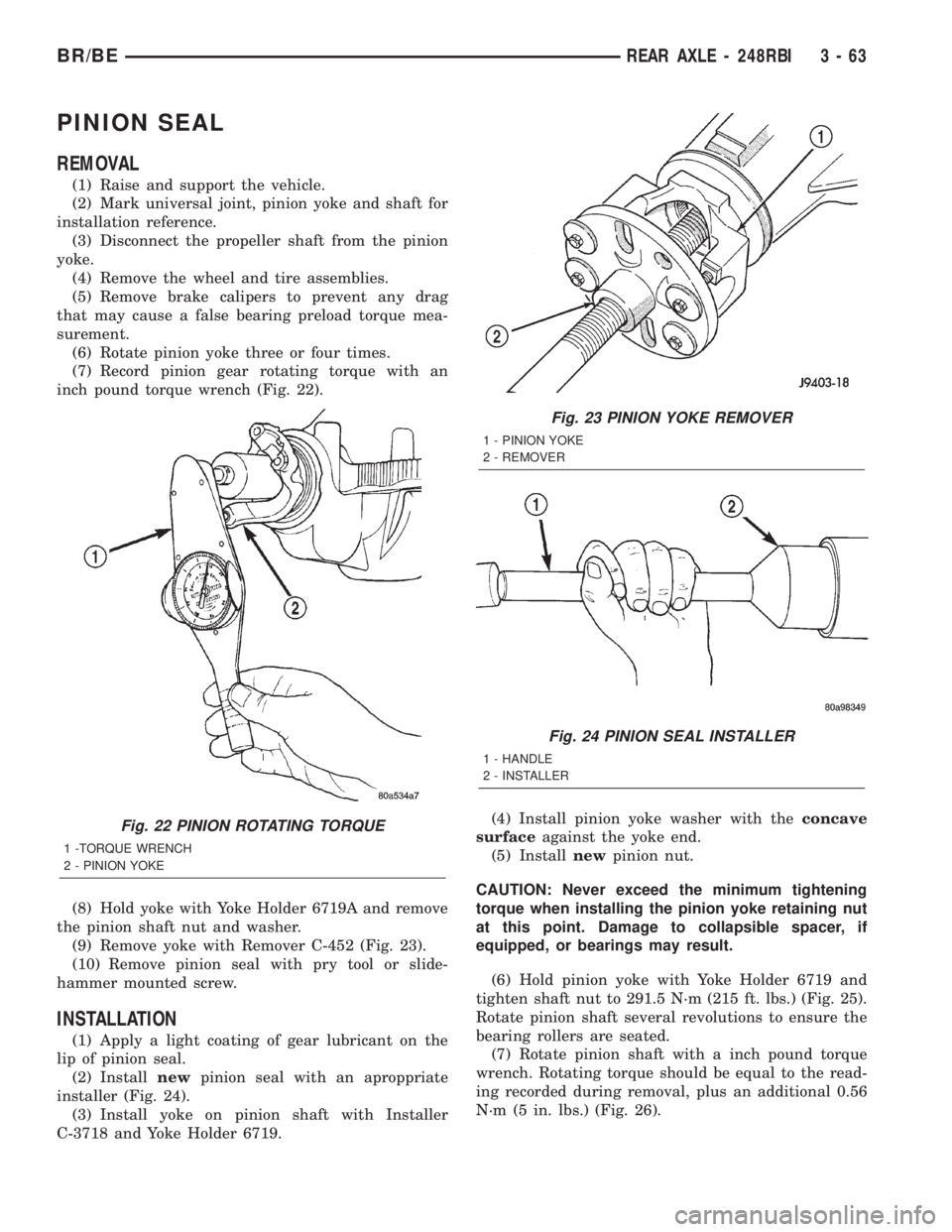
inch pound torque wrench (Fig. 22).
(8) Hold yoke with Yoke Holder 6719A and remove
the pinion shaft nut and washer.
(9) Remove yoke with Remover C-452 (Fig. 23).
(10) Remove pinion seal with pry tool or slide-
hammer mounted screw.
INSTALLATION
(1) Apply a light coating of gear lubricant on the
lip of pinion seal.
(2) Installnewpinion seal with an aproppriate
installer (Fig. 24).
(3) Install yoke on pinion shaft with Installer
C-3718 and Yoke Holder 6719.(4) Install pinion yoke washer with theconcave
surfaceagainst the yoke end.
(5) Installnewpinion nut.
CAUTION: Never exceed the minimum tightening
torque when installing the pinion yoke retaining nut
at this point. Damage to collapsible spacer, if
equipped, or bearings may result.
(6) Hold pinion yoke with Yoke Holder 6719 and
tighten shaft nut to 291.5 N´m (215 ft. lbs.) (Fig. 25).
Rotate pinion shaft several revolutions to ensure the
bearing rollers are seated.
(7) Rotate pinion shaft with a inch pound torque
wrench. Rotating torque should be equal to the read-
ing recorded during removal, plus an additional 0.56
N´m (5 in. lbs.) (Fig. 26).
Fig. 22 PINION ROTATING TORQUE
1 -TORQUE WRENCH
2 - PINION YOKE
Fig. 23 PINION YOKE REMOVER
1 - PINION YOKE
2 - REMOVER
Fig. 24 PINION SEAL INSTALLER
1 - HANDLE
2 - INSTALLER
BR/BEREAR AXLE - 248RBI 3 - 63
Page 119 of 2255
CAUTION: Never loosen pinion gear nut to decrease
pinion rotating torque and never exceed specified pre-
load torque. If preload torque is exceeded a new pin-ion nut and collapsible spacer, if equipped, must be
installed.
(8) If rotating torque is low, use Yoke Holder 6719
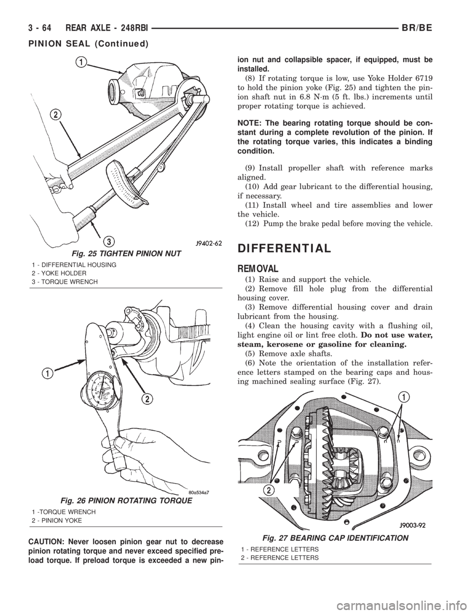
to hold the pinion yoke (Fig. 25) and tighten the pin-
ion shaft nut in 6.8 N´m (5 ft. lbs.) increments until
proper rotating torque is achieved.
NOTE: The bearing rotating torque should be con-
stant during a complete revolution of the pinion. If
the rotating torque varies, this indicates a binding
condition.
(9) Install propeller shaft with reference marks
aligned.
(10) Add gear lubricant to the differential housing,
if necessary.
(11) Install wheel and tire assemblies and lower
the vehicle.
(12)
Pump the brake pedal before moving the vehicle.
DIFFERENTIAL
REMOVAL
(1) Raise and support the vehicle.
(2) Remove fill hole plug from the differential
housing cover.
(3) Remove differential housing cover and drain
lubricant from the housing.
(4) Clean the housing cavity with a flushing oil,
light engine oil or lint free cloth.Do not use water,
steam, kerosene or gasoline for cleaning.
(5) Remove axle shafts.
(6) Note the orientation of the installation refer-
ence letters stamped on the bearing caps and hous-
ing machined sealing surface (Fig. 27).
Fig. 25 TIGHTEN PINION NUT
1 - DIFFERENTIAL HOUSING
2 - YOKE HOLDER
3 - TORQUE WRENCH
Fig. 26 PINION ROTATING TORQUE
1 -TORQUE WRENCH
2 - PINION YOKE
Fig. 27 BEARING CAP IDENTIFICATION
1 - REFERENCE LETTERS
2 - REFERENCE LETTERS
3 - 64 REAR AXLE - 248RBIBR/BE
PINION SEAL (Continued)
Page 150 of 2255
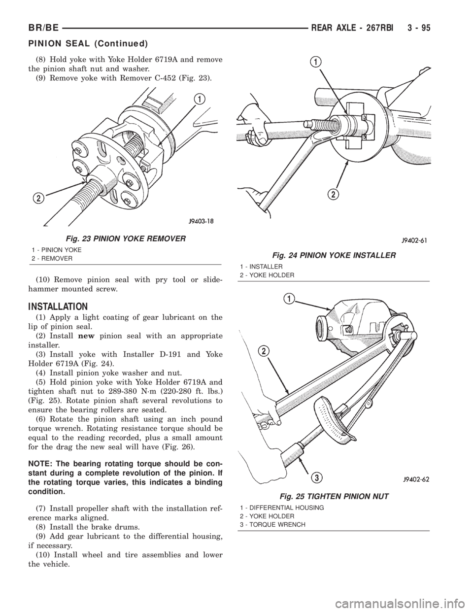
(8) Hold yoke with Yoke Holder 6719A and remove
the pinion shaft nut and washer.
(9) Remove yoke with Remover C-452 (Fig. 23).
(10) Remove pinion seal with pry tool or slide-
hammer mounted screw.
INSTALLATION
(1) Apply a light coating of gear lubricant on the
lip of pinion seal.
(2) Installnewpinion seal with an appropriate
installer.
(3) Install yoke with Installer D-191 and Yoke
Holder 6719A (Fig. 24).
(4) Install pinion yoke washer and nut.
(5) Hold pinion yoke with Yoke Holder 6719A and
tighten shaft nut to 289-380 N´m (220-280 ft. lbs.)
(Fig. 25). Rotate pinion shaft several revolutions to
ensure the bearing rollers are seated.
(6) Rotate the pinion shaft using an inch pound
torque wrench. Rotating resistance torque should be
equal to the reading recorded, plus a small amount
for the drag the new seal will have (Fig. 26).
NOTE: The bearing rotating torque should be con-
stant during a complete revolution of the pinion. If
the rotating torque varies, this indicates a binding
condition.
(7) Install propeller shaft with the installation ref-
erence marks aligned.
(8) Install the brake drums.
(9) Add gear lubricant to the differential housing,
if necessary.
(10) Install wheel and tire assemblies and lower
the vehicle.
Fig. 23 PINION YOKE REMOVER
1 - PINION YOKE
2 - REMOVERFig. 24 PINION YOKE INSTALLER
1 - INSTALLER
2 - YOKE HOLDER
Fig. 25 TIGHTEN PINION NUT
1 - DIFFERENTIAL HOUSING
2 - YOKE HOLDER
3 - TORQUE WRENCH
BR/BEREAR AXLE - 267RBI 3 - 95
PINION SEAL (Continued)
Page 179 of 2255
INSTALLATION
(1) Clean the seal contact surface in the housing
bore.
(2) Apply a light coating of gear lubricant on the
lip of pinion seal.
(3) Installnewpinion shaft seal with an appropri-
ate Installer.
(4) Position pinion yoke on the end of the shaft
with the reference marks aligned.
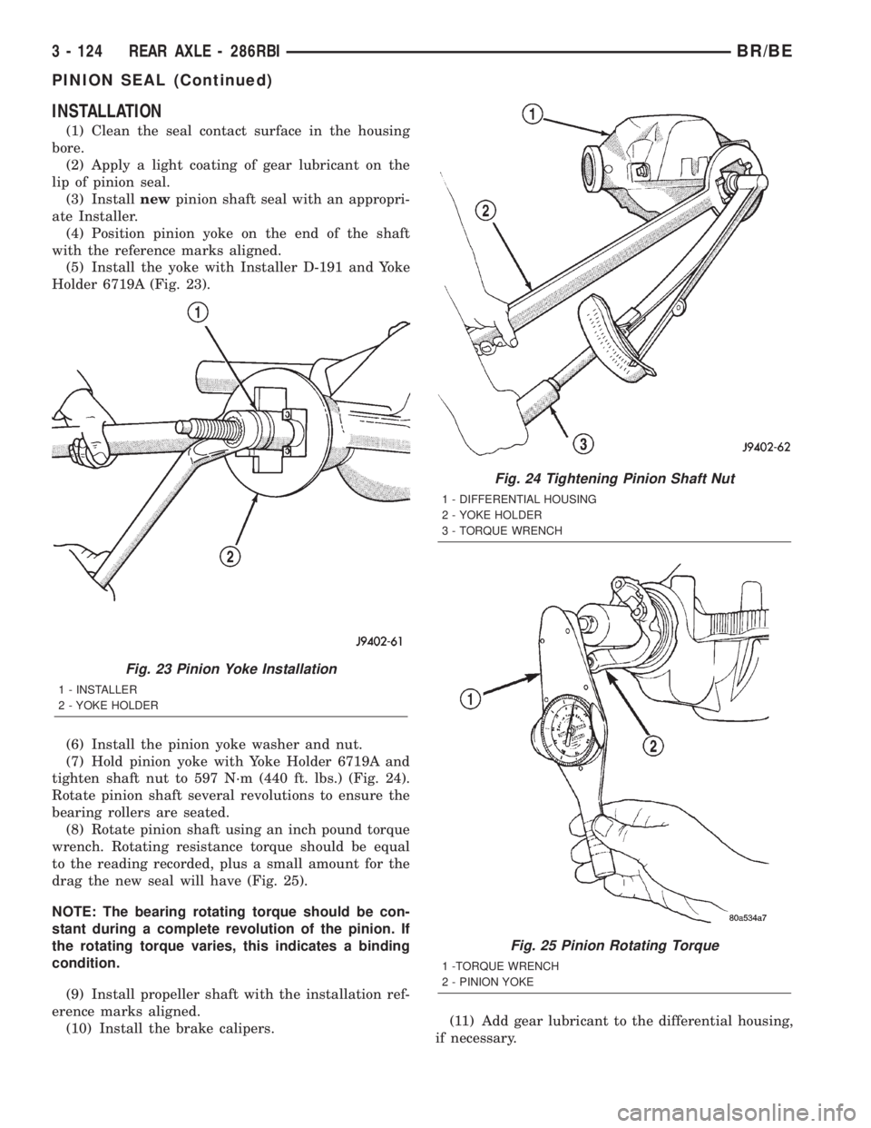
(5) Install the yoke with Installer D-191 and Yoke
Holder 6719A (Fig. 23).
(6) Install the pinion yoke washer and nut.
(7) Hold pinion yoke with Yoke Holder 6719A and
tighten shaft nut to 597 N´m (440 ft. lbs.) (Fig. 24).
Rotate pinion shaft several revolutions to ensure the
bearing rollers are seated.
(8) Rotate pinion shaft using an inch pound torque
wrench. Rotating resistance torque should be equal
to the reading recorded, plus a small amount for the
drag the new seal will have (Fig. 25).
NOTE: The bearing rotating torque should be con-
stant during a complete revolution of the pinion. If
the rotating torque varies, this indicates a binding
condition.
(9) Install propeller shaft with the installation ref-
erence marks aligned.
(10) Install the brake calipers.(11) Add gear lubricant to the differential housing,
if necessary.
Fig. 23 Pinion Yoke Installation
1 - INSTALLER
2 - YOKE HOLDER
Fig. 24 Tightening Pinion Shaft Nut
1 - DIFFERENTIAL HOUSING
2 - YOKE HOLDER
3 - TORQUE WRENCH
Fig. 25 Pinion Rotating Torque
1 -TORQUE WRENCH
2 - PINION YOKE
3 - 124 REAR AXLE - 286RBIBR/BE
PINION SEAL (Continued)
Page 195 of 2255

SPONGY PEDAL
A spongy pedal is most often caused by air in the
system. However, thin brake drums or substandard
brake lines and hoses can also cause a spongy pedal.
The proper course of action is to bleed the system,
and replace thin drums and substandard quality
brake hoses if suspected.
HARD PEDAL OR HIGH PEDAL EFFORT
A hard pedal or high pedal effort may be due to
lining that is water soaked, contaminated, glazed, or
badly worn. The power booster or check valve could
also be faulty.
PEDAL PULSATION
Pedal pulsation is caused by components that are
loose, or beyond tolerance limits.
The primary cause of pulsation are disc brake
rotors with excessive lateral runout or thickness vari-
ation, or out of round brake drums. Other causes are
loose wheel bearings or calipers and worn or dam-
aged tires.
NOTE: Some pedal pulsation may be felt during
ABS/EBD activation.
BRAKE DRAG
Brake drag occurs when the lining is in constant
contact with the rotor or drum. Drag can occur at one
wheel, all wheels, fronts only, or rears only.
Drag is a product of incomplete brake shoe release.
Drag can be minor or severe enough to overheat the
linings, rotors and drums.
Minor drag will usually cause slight surface char-
ring of the lining. It can also generate hard spots in
rotors and drums from the overheat-cool down pro-
cess. In most cases, the rotors, drums, wheels and
tires are quite warm to the touch after the vehicle is
stopped.
Severe drag can char the brake lining all the way
through. It can also distort and score rotors and
drums to the point of replacement. The wheels, tires
and brake components will be extremely hot. In
severe cases, the lining may generate smoke as it
chars from overheating.
Common causes of brake drag are:
²Seized or improperly adjusted parking brake
cables
²Loose/worn wheel bearing
²Seized caliper or wheel cylinder piston
²Caliper binding on damaged or missing anti-rat-
tle clips or bushings
²Loose caliper mounting
²Drum brake shoes binding on worn/damaged
support plates
²Mis-assembled components²Long booster output rod
If brake drag occurs at all wheels, the problem
may be related to a blocked master cylinder return
port, or faulty power booster (binds-does not release).
BRAKE FADE
Brake fade is usually a product of overheating
caused by brake drag. However, brake overheating
and resulting fade can also be caused by riding the
brake pedal, making repeated high deceleration stops
in a short time span, or constant braking on steep
mountain roads. Refer to the Brake Drag information
in this section for causes.
BRAKE PULL
Front brake pull condition could result from:
²Contaminated lining in one caliper
²Seized caliper piston
²Binding caliper
²Loose caliper
²Damaged anti-rattle clips
²Improper brake shoes
²Damaged rotor
A worn, damaged wheel bearing or suspension
component are further causes of pull. A damaged
front tire (bruised, ply separation) can also cause
pull.
A common and frequently misdiagnosed pull condi-
tion is where direction of pull changes after a few
stops. The cause is a combination of brake drag fol-
lowed by fade at one of the brake units.
As the dragging brake overheats, efficiency is so
reduced that fade occurs. Since the opposite brake
unit is still functioning normally, its braking effect is
magnified. This causes pull to switch direction in
favor of the normally functioning brake unit.
An additional point when diagnosing a change in
pull condition concerns brake cool down. Remember
that pull will return to the original direction, if the
dragging brake unit is allowed to cool down (and is
not seriously damaged).
REAR BRAKE GRAB OR PULL
Rear grab or pull is usually caused by improperly
adjusted or seized parking brake cables, contami-
nated lining, bent or binding shoes and support
plates, or improperly assembled components. This is
particularly true when only one rear wheel is
involved. However, when both rear wheels are
affected, the master cylinder or proportioning valve
could be at fault.
BRAKES DO NOT HOLD AFTER DRIVING THROUGH DEEP
WATER PUDDLES
This condition is generally caused by water soaked
lining. If the lining is only wet, it can be dried by
driving with the brakes very lightly applied for a
5 - 6 BRAKES - BASEBR/BE
HYDRAULIC/MECHANICAL (Continued)