2002 DODGE RAM dead battery
[x] Cancel search: dead batteryPage 392 of 2255

BATTERY SYSTEM DIAGNOSIS
CONDITION POSSIBLE CAUSES CORRECTION
THE BATTERY SEEMS
WEAK OR DEAD WHEN
ATTEMPTING TO START
THE ENGINE.1. The electrical system
ignition-off draw is excessive.1. Refer to the IGNITION-OFF DRAW TEST
Standard Procedure for the proper test
procedures. Repair the excessive ignition-off
draw, as required.
2. The charging system is
faulty.2. Determine if the charging system is performing
to specifications using the Midtronics battery and
charging system tester. Refer to Charging System
for additional charging system diagnosis and
testing procedures. Repair the faulty charging
system, as required.
3. The battery is discharged. 3. Determine the battery state-of-charge using the
Midtronics battery and charging system tester.
Refer to the Standard Procedures in this section
for additional test procedures. Charge the faulty
battery, as required.
4. The battery terminal
connections are loose or
corroded.4. Refer to Battery Cables for the proper battery
cable diagnosis and testing procedures. Clean
and tighten the battery terminal connections, as
required.
5. The battery has an
incorrect size or rating for
this vehicle.5. Refer to Battery System Specifications for the
proper size and rating. Replace an incorrect
battery, as required.
6. The battery is faulty. 6. Determine the battery cranking capacity using
the Midtronics battery and charging system tester.
Refer to the Standard Procedures in this section
for additional test procedures. Replace the faulty
battery, as required.
7. The starting system is
faulty.7. Determine if the starting system is performing
to specifications. Refer to Starting System for the
proper starting system diagnosis and testing
procedures. Repair the faulty starting system, as
required.
8. The battery is physically
damaged.8. Inspect the battery for loose terminal posts or a
cracked and leaking case. Replace the damaged
battery, as required.
BR/BEBATTERY SYSTEM 8F - 3
BATTERY SYSTEM (Continued)
Page 464 of 2255

the ECM relating engine speed and crankshaft posi-
tion.
The sensor detects machined notches on the rear
face of the camshaft drive gear (Fig. 7) to sense
engine speed.
The CMP also detects an area on the camshaft
drive gear that has no notch (Fig. 7). When the sen-
sor passes this area, it tells the Engine Control Mod-
ule (ECM) that Top Dead Center (TDC) of the
number 1 cylinder is occurring. The ECM will then
adjust fuel timing accordingly.
As the tip of the sensor passes the notches, the
interruption of magnetic field causes voltage changes
from 5 volts to 0 volts.
OPERATION - 5.9L
The sensor contains a hall effect device called a
sync signal generator to generate a fuel sync signal.
This sync signal generator detects a rotating pulse
ring (shutter) on the distributor shaft. The pulse ring
rotates 180 degrees through the sync signal genera-
tor. Its signal is used in conjunction with the Crank-
shaft Position (CKP) sensor to differentiate between
fuel injection and spark events. It is also used to syn-
chronize the fuel injectors with their respective cylin-
ders.
When the leading edge of the pulse ring (shutter)
enters the sync signal generator, the following occurs:
The interruption of magnetic field causes the voltageto switch high resulting in a sync signal of approxi-
mately 5 volts.
When the trailing edge of the pulse ring (shutter)
leaves the sync signal generator, the following occurs:
The change of the magnetic field causes the sync sig-
nal voltage to switch low to 0 volts.
OPERATION - 8.0L
The CMP sensor is used in conjunction with the
crankshaft position sensor to differentiate between
fuel injection and spark events. It is also used to syn-
chronize the fuel injectors with their respective cylin-
ders. The sensor generates electrical pulses. These
pulses (signals) are sent to the Powertrain Control
Module (PCM). The PCM will then determine crank-
shaft position from both the camshaft position sensor
and crankshaft position sensor.
A low and high area are machined into the cam-
shaft drive gear (Fig. 8). The sensor is positioned in
the timing gear cover so that a small air gap (Fig. 8)
exists between the face of sensor and the high
machined area of cam gear.
When the cam gear is rotating, the sensor will
detect the machined low area. Input voltage from the
sensor to the PCM will then switch from a low
(approximately 0.3 volts) to a high (approximately 5
volts). When the sensor detects the high machined
area, the input voltage switches back low to approx-
imately 0.3 volts.
REMOVAL
REMOVAL - DIESEL
The camshaft position sensor (CMP) is located
below the fuel injection pump (Fig. 9). It is attached
to the back of the timing gear cover housing.
(1) Disconnect both negative cables from both bat-
teries.
(2) Clean area around CMP.
(3) Disconnect electrical at CMP (Fig. 9).
(4) Remove CMP mounting bolt. Bolt head is
female-hex (Fig. 10).
(5) Remove CMP from engine by twisting and pull-
ing straight back.
(6) Discard CMP o-ring (Fig. 10).
REMOVAL - 5.9L
The camshaft position sensor is located in the dis-
tributor (Fig. 11).
Distributor removal is not necessary to remove
camshaft position sensor.
(1) Remove air cleaner assembly.
(2) Disconnect negative cable from battery.
(3) Remove distributor cap from distributor (two
screws).
Fig. 7 Notches at Rear Of Camshaft Drive Gear
1 - CAMSHAFT DRIVE GEAR
2 - NOTCHES
3 - CAMSHAFT POSITION SENSOR (CKP)
4 - NO NOTCH
BR/BEIGNITION CONTROL 8I - 7
CAMSHAFT POSITION SENSOR (Continued)
Page 469 of 2255
OPERATION
The camshaft position sensor provides fuel injec-
tion synchronization and cylinder identification.
The distributor does not have built in centrifugal
or vacuum assisted advance. Base ignition timing
and all timing advance is controlled by the Power-
train Control Module (PCM). Because ignition timing
is controlled by the PCM,base ignition timing is
not adjustable.
The distributor is held to the engine in the conven-
tional method using a holddown clamp and bolt.
Although the distributor can be rotated, it will
have no effect on ignition timing.
All distributors contain an internal oil seal that
prevents oil from entering the distributor housing.
The seal is not serviceable.
REMOVAL
CAUTION: Base ignition timing is not adjustable on
any engine. Distributors do not have built in centrif-
ugal or vacuum assisted advance. Base ignition
timing and timing advance are controlled by the
Powertrain Control Module (PCM). Because a con-
ventional timing light can not be used to adjust dis-
tributor position after installation, note position of
distributor before removal.
(1) Remove air cleaner assembly.
(2) Disconnect negative cable from battery.
(3) Remove distributor cap from distributor (two
screws).
(4) Mark the position of distributor housing in
relationship to engine or dash panel. This is done to
aid in installation.
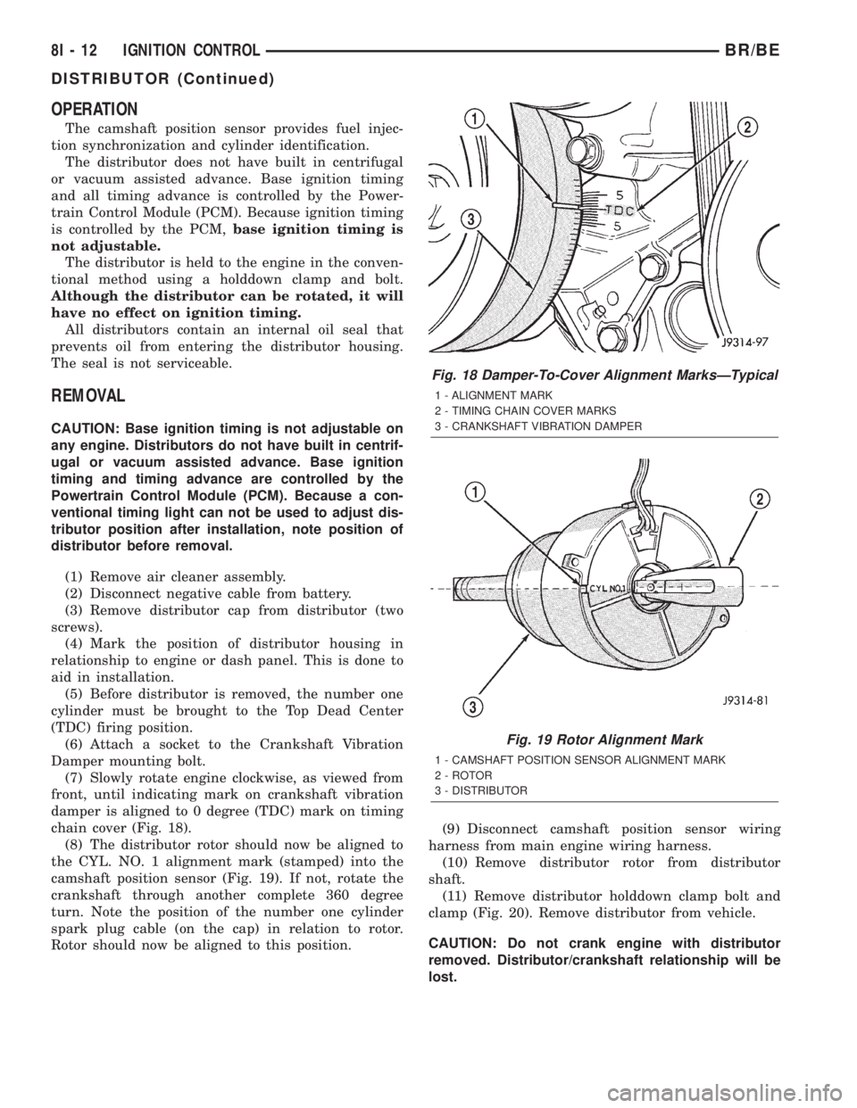
(5) Before distributor is removed, the number one
cylinder must be brought to the Top Dead Center
(TDC) firing position.
(6) Attach a socket to the Crankshaft Vibration
Damper mounting bolt.
(7) Slowly rotate engine clockwise, as viewed from
front, until indicating mark on crankshaft vibration
damper is aligned to 0 degree (TDC) mark on timing
chain cover (Fig. 18).
(8) The distributor rotor should now be aligned to
the CYL. NO. 1 alignment mark (stamped) into the
camshaft position sensor (Fig. 19). If not, rotate the
crankshaft through another complete 360 degree
turn. Note the position of the number one cylinder
spark plug cable (on the cap) in relation to rotor.
Rotor should now be aligned to this position.(9) Disconnect camshaft position sensor wiring
harness from main engine wiring harness.
(10) Remove distributor rotor from distributor
shaft.
(11) Remove distributor holddown clamp bolt and
clamp (Fig. 20). Remove distributor from vehicle.
CAUTION: Do not crank engine with distributor
removed. Distributor/crankshaft relationship will be
lost.
Fig. 18 Damper-To-Cover Alignment MarksÐTypical
1 - ALIGNMENT MARK
2 - TIMING CHAIN COVER MARKS
3 - CRANKSHAFT VIBRATION DAMPER
Fig. 19 Rotor Alignment Mark
1 - CAMSHAFT POSITION SENSOR ALIGNMENT MARK
2 - ROTOR
3 - DISTRIBUTOR
8I - 12 IGNITION CONTROLBR/BE
DISTRIBUTOR (Continued)
Page 642 of 2255

POWER-UP MODE
When the armed VTSS senses that the battery has
been disconnected and reconnected, it enters its pow-
er-up mode. In the power-up mode the alarm system
remains armed following a battery failure or discon-
nect. If the VTSS was armed prior to a battery dis-
connect or failure, the technician or vehicle operator
will have to actively or passively disarm the alarm
system after the battery is reconnected. The pow-
er-up mode will also apply if the battery goes dead
while the system is armed, and battery jump-starting
is attempted. The engine no-run feature will prevent
the engine from starting until the alarm system has
been actively or passively disarmed. The VTSS will
be armed until the technician or vehicle operator has
actively or passively disarmed the alarm system. If
the VTSS is in the disarmed mode prior to a battery
disconnect or failure, it will remain disarmed after
the battery is reconnected or replaced, or if jump-
starting is attempted.
TAMPER ALERT
The VTSS tamper alert feature will sound the horn
three times upon disarming, if the alarm was trig-
gered and has since timed-out (about fifteen min-
utes). This feature alerts the vehicle operator that
the VTSS alarm was activated while the vehicle was
unattended.
DIAGNOSIS AND TESTING - VEHICLE THEFT
SECURITY SYSTEM
The VTSS-related hard wired inputs to and out-
puts from the high-line or premium Central Timer
Module (CTM) may be diagnosed and tested using
conventional diagnostic tools and procedures. Refer
to the appropriate wiring information. The wiring
information includes wiring diagrams, proper wire
and connector repair procedures, further details on
wire harness routing and retention, as well as pin-
out and location views for the various wire harness
connectors, splices and grounds.
However, conventional diagnostic methods may not
prove conclusive in the diagnosis of the CTM, the
Powertrain Control Module (PCM), or the Chrysler
Collision Detection (CCD) data bus network. In order
to obtain conclusive testing of the VTSS, the CTM,
the PCM, and the CCD data bus network must also
be checked. The most reliable, efficient, and accurate
means to diagnose the VTSS requires the use of a
DRBIIItscan tool. Refer to the appropriate diagnos-
tic information. The DRBIIItscan tool can provide
confirmation that the CCD data bus network is func-
tional, that all of the electronic modules are sending
and receiving the proper messages over the CCD
data bus, and that these modules are receiving the
proper hard wired inputs and responding with theproper hard wired outputs needed to perform their
functions. See the ªVehicle Theft Security Systemº
menu item on the DRBIIItscan tool.
WARNING: ON VEHICLES EQUIPPED WITH AIR-
BAGS, DISABLE THE AIRBAG SYSTEM BEFORE
ATTEMPTING ANY STEERING WHEEL, STEERING
COLUMN, OR INSTRUMENT PANEL COMPONENT
DIAGNOSIS OR SERVICE. DISCONNECT AND ISO-
LATE THE BATTERY NEGATIVE (GROUND) CABLE,
THEN WAIT TWO MINUTES FOR THE AIRBAG SYS-
TEM CAPACITOR TO DISCHARGE BEFORE PER-
FORMING FURTHER DIAGNOSIS OR SERVICE. THIS
IS THE ONLY SURE WAY TO DISABLE THE AIRBAG
SYSTEM. FAILURE TO TAKE THE PROPER PRE-
CAUTIONS COULD RESULT IN ACCIDENTAL AIR-
BAG DEPLOYMENT AND POSSIBLE PERSONAL
INJURY.
VTSS INDICATOR
DESCRIPTION
The Vehicle Theft Security System (VTSS) indica-
tor consists of a red Light-Emitting Diode (LED)
located on the electronic circuit board of the Compass
Mini-Trip Computer (CMTC) within the overhead
console. The LED extends through a hole in the
CMTC lens located near the forward end of the over-
head console housing near the windshield.
The VTSS indicator cannot be adjusted or repaired
and, if faulty or damaged, the entire CMTC unit
must be replaced. (Refer to 8 - ELECTRICAL/OVER-
HEAD CONSOLE/COMPASS/MINI-TRIP COM-
PUTER - DESCRIPTION).
OPERATION
The Vehicle Theft Security System (VTSS) indica-
tor gives a visible indication of the VTSS arming sta-
tus. One side of Light-Emitting Diode (LED) in the
VTSS indicator is connected to battery current
through a fused B(+) circuit and a fuse in the Junc-
tion Block (JB), so the indicator remains functional
regardless of the ignition switch position. The other
side of the LED is hard wired to the Central Timer
Module (CTM), which controls the operation of the
VTSS indicator by pulling this side of the LED cir-
cuit to ground. When the VTSS arming is in
progress, the CTM will flash the LED rapidly on and
off for about fifteen seconds. When the VTSS has
been successfully armed, the CTM will flash the LED
on and off continually at a much slower rate until
the VTSS has been disarmed. The VTSS indicator
can be diagnosed using conventional diagnostic tools
and methods.
BR/BEVEHICLE THEFT SECURITY 8Q - 3
VEHICLE THEFT SECURITY (Continued)
Page 1079 of 2255
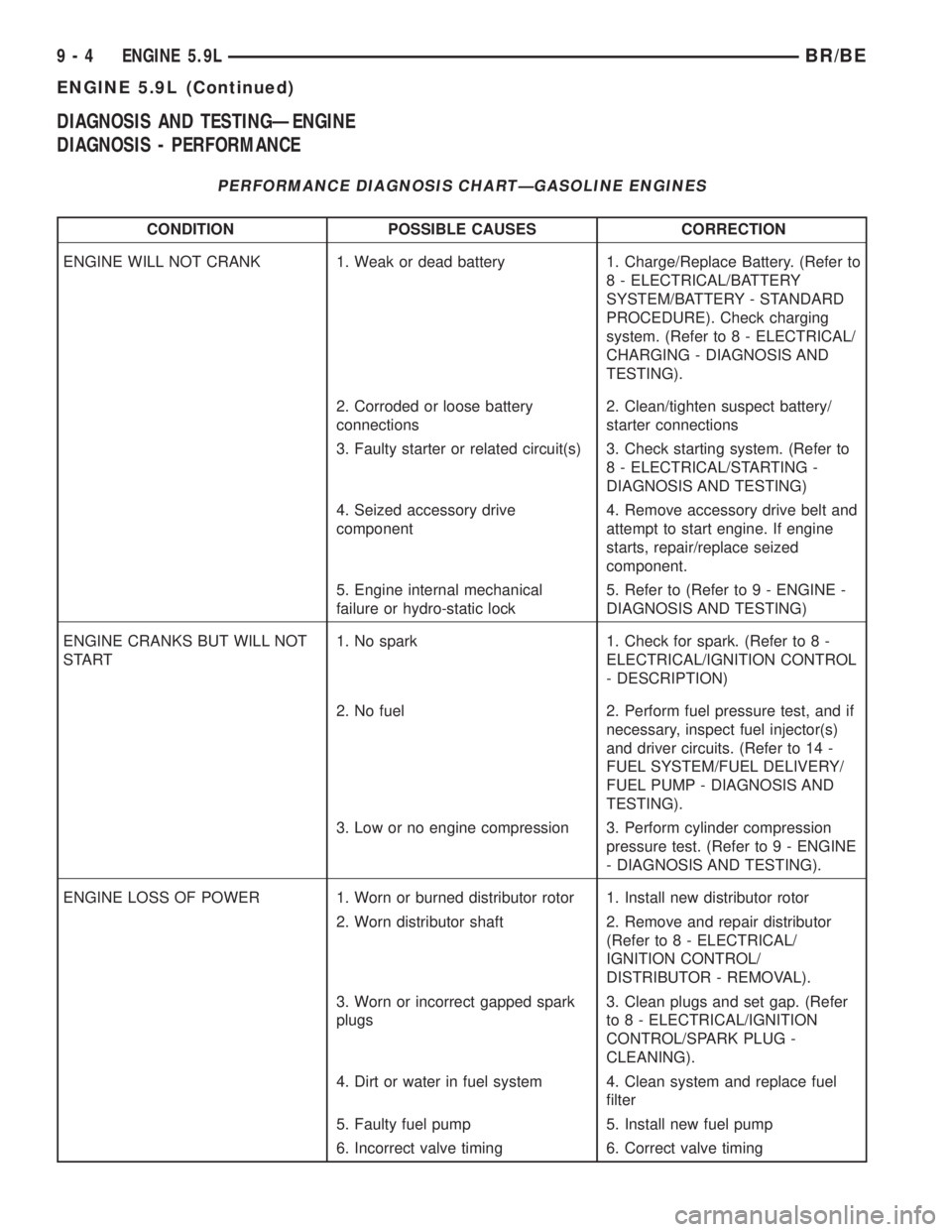
DIAGNOSIS AND TESTINGÐENGINE
DIAGNOSIS - PERFORMANCE
PERFORMANCE DIAGNOSIS CHARTÐGASOLINE ENGINES
CONDITION POSSIBLE CAUSES CORRECTION
ENGINE WILL NOT CRANK 1. Weak or dead battery 1. Charge/Replace Battery. (Refer to
8 - ELECTRICAL/BATTERY
SYSTEM/BATTERY - STANDARD
PROCEDURE). Check charging
system. (Refer to 8 - ELECTRICAL/
CHARGING - DIAGNOSIS AND
TESTING).
2. Corroded or loose battery
connections2. Clean/tighten suspect battery/
starter connections
3. Faulty starter or related circuit(s) 3. Check starting system. (Refer to
8 - ELECTRICAL/STARTING -
DIAGNOSIS AND TESTING)
4. Seized accessory drive
component4. Remove accessory drive belt and
attempt to start engine. If engine
starts, repair/replace seized
component.
5. Engine internal mechanical
failure or hydro-static lock5. Refer to (Refer to 9 - ENGINE -
DIAGNOSIS AND TESTING)
ENGINE CRANKS BUT WILL NOT
START1. No spark 1. Check for spark. (Refer to 8 -
ELECTRICAL/IGNITION CONTROL
- DESCRIPTION)
2. No fuel 2. Perform fuel pressure test, and if
necessary, inspect fuel injector(s)
and driver circuits. (Refer to 14 -
FUEL SYSTEM/FUEL DELIVERY/
FUEL PUMP - DIAGNOSIS AND
TESTING).
3. Low or no engine compression 3. Perform cylinder compression
pressure test. (Refer to 9 - ENGINE
- DIAGNOSIS AND TESTING).
ENGINE LOSS OF POWER 1. Worn or burned distributor rotor 1. Install new distributor rotor
2. Worn distributor shaft 2. Remove and repair distributor
(Refer to 8 - ELECTRICAL/
IGNITION CONTROL/
DISTRIBUTOR - REMOVAL).
3. Worn or incorrect gapped spark
plugs3. Clean plugs and set gap. (Refer
to 8 - ELECTRICAL/IGNITION
CONTROL/SPARK PLUG -
CLEANING).
4. Dirt or water in fuel system 4. Clean system and replace fuel
filter
5. Faulty fuel pump 5. Install new fuel pump
6. Incorrect valve timing 6. Correct valve timing
9 - 4 ENGINE 5.9LBR/BE
ENGINE 5.9L (Continued)
Page 1134 of 2255
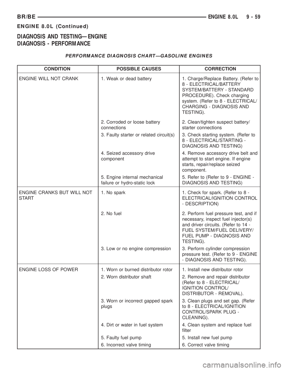
DIAGNOSIS AND TESTINGÐENGINE
DIAGNOSIS - PERFORMANCE
PERFORMANCE DIAGNOSIS CHARTÐGASOLINE ENGINES
CONDITION POSSIBLE CAUSES CORRECTION
ENGINE WILL NOT CRANK 1. Weak or dead battery 1. Charge/Replace Battery. (Refer to
8 - ELECTRICAL/BATTERY
SYSTEM/BATTERY - STANDARD
PROCEDURE). Check charging
system. (Refer to 8 - ELECTRICAL/
CHARGING - DIAGNOSIS AND
TESTING).
2. Corroded or loose battery
connections2. Clean/tighten suspect battery/
starter connections
3. Faulty starter or related circuit(s) 3. Check starting system. (Refer to
8 - ELECTRICAL/STARTING -
DIAGNOSIS AND TESTING)
4. Seized accessory drive
component4. Remove accessory drive belt and
attempt to start engine. If engine
starts, repair/replace seized
component.
5. Engine internal mechanical
failure or hydro-static lock5. Refer to (Refer to 9 - ENGINE -
DIAGNOSIS AND TESTING)
ENGINE CRANKS BUT WILL NOT
START1. No spark 1. Check for spark. (Refer to 8 -
ELECTRICAL/IGNITION CONTROL
- DESCRIPTION)
2. No fuel 2. Perform fuel pressure test, and if
necessary, inspect fuel injector(s)
and driver circuits. (Refer to 14 -
FUEL SYSTEM/FUEL DELIVERY/
FUEL PUMP - DIAGNOSIS AND
TESTING).
3. Low or no engine compression 3. Perform cylinder compression
pressure test. (Refer to 9 - ENGINE
- DIAGNOSIS AND TESTING).
ENGINE LOSS OF POWER 1. Worn or burned distributor rotor 1. Install new distributor rotor
2. Worn distributor shaft 2. Remove and repair distributor
(Refer to 8 - ELECTRICAL/
IGNITION CONTROL/
DISTRIBUTOR - REMOVAL).
3. Worn or incorrect gapped spark
plugs3. Clean plugs and set gap. (Refer
to 8 - ELECTRICAL/IGNITION
CONTROL/SPARK PLUG -
CLEANING).
4. Dirt or water in fuel system 4. Clean system and replace fuel
filter
5. Faulty fuel pump 5. Install new fuel pump
6. Incorrect valve timing 6. Correct valve timing
BR/BEENGINE 8.0L 9 - 59
ENGINE 8.0L (Continued)
Page 1157 of 2255
allowable tensions. Discard the springs that do not
meet specifications.
REMOVAL
REMOVALÐVALVE STEM SEALS
NOTE: This procedure is done with the cylinder
head installed.
(1) Disconnect the negative cable from the battery.
(2) Set engine basic timing to Top Dead Center
(TDC) and remove air cleaner.
(3) Remove cylinder head covers (Refer to 9 -
ENGINE/CYLINDER HEAD/CYLINDER HEAD
COVER(S) - REMOVAL) and spark plugs (Refer to 8
- ELECTRICAL/IGNITION CONTROL/SPARK
PLUG - REMOVAL).
(4) Using suitable socket and flex handle at crank-
shaft retaining bolt, turn engine so that the piston of
the cylinder to be worked on, is at TDC on the com-
pression stroke.
(5) Remove rocker arms (Refer to 9 - ENGINE/
CYLINDER HEAD/ROCKER ARM / ADJUSTER
ASSY - REMOVAL).
(6) With air hose attached to an adapter installed
in the spark plug hole, apply 620-689 kPa (90-100
psi) air pressure.
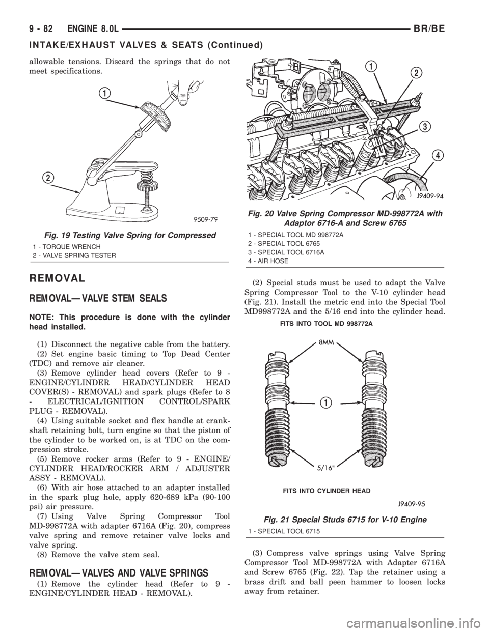
(7) Using Valve Spring Compressor Tool
MD-998772A with adapter 6716A (Fig. 20), compress
valve spring and remove retainer valve locks and
valve spring.
(8) Remove the valve stem seal.
REMOVALÐVALVES AND VALVE SPRINGS
(1) Remove the cylinder head (Refer to 9 -
ENGINE/CYLINDER HEAD - REMOVAL).(2) Special studs must be used to adapt the Valve
Spring Compressor Tool to the V-10 cylinder head
(Fig. 21). Install the metric end into the Special Tool
MD998772A and the 5/16 end into the cylinder head.
(3) Compress valve springs using Valve Spring
Compressor Tool MD-998772A with Adapter 6716A
and Screw 6765 (Fig. 22). Tap the retainer using a
brass drift and ball peen hammer to loosen locks
away from retainer.
Fig. 19 Testing Valve Spring for Compressed
1 - TORQUE WRENCH
2 - VALVE SPRING TESTER
Fig. 20 Valve Spring Compressor MD-998772A with
Adaptor 6716-A and Screw 6765
1 - SPECIAL TOOL MD 998772A
2 - SPECIAL TOOL 6765
3 - SPECIAL TOOL 6716A
4 - AIR HOSE
Fig. 21 Special Studs 6715 for V-10 Engine
1 - SPECIAL TOOL 6715
9 - 82 ENGINE 8.0LBR/BE
INTAKE/EXHAUST VALVES & SEATS (Continued)
Page 1216 of 2255
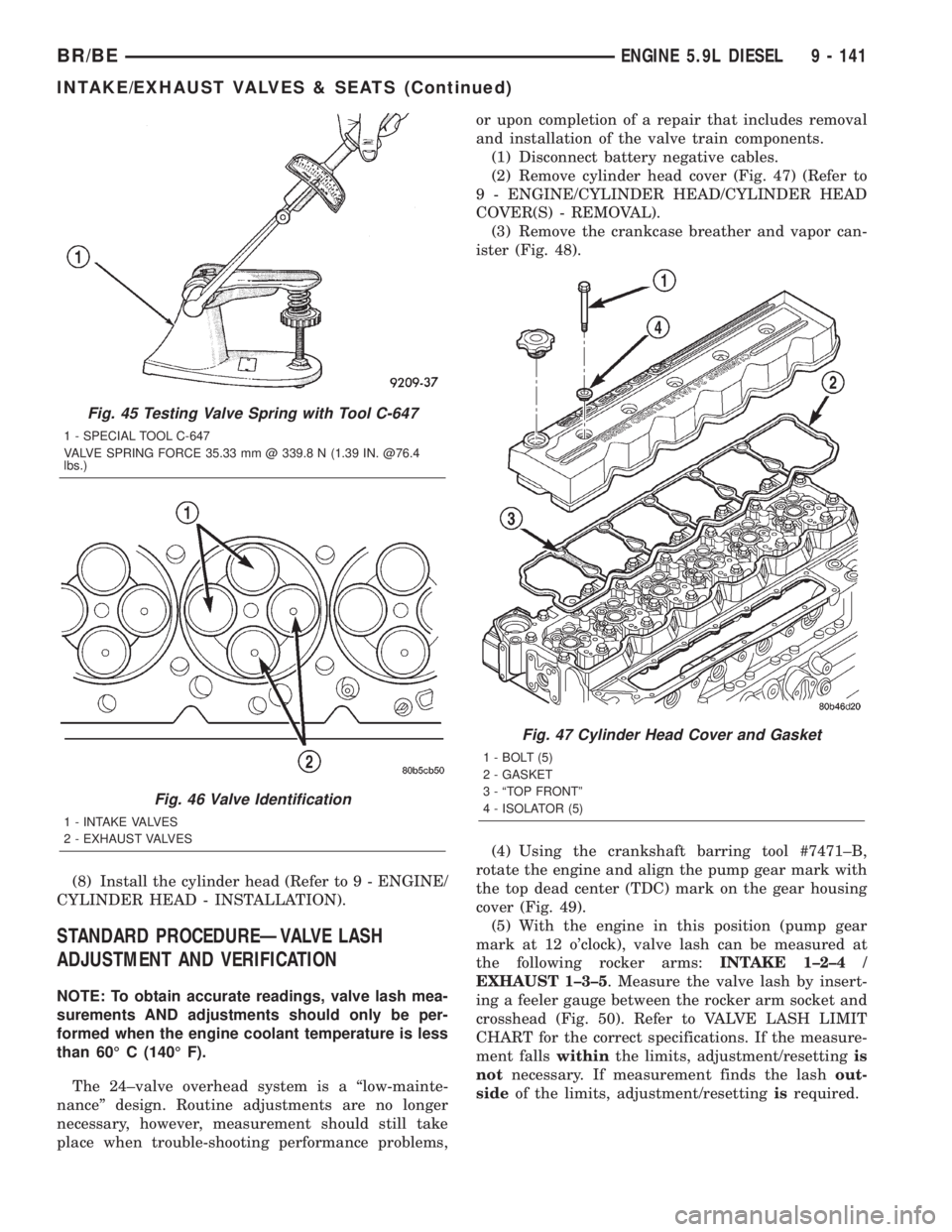
(8) Install the cylinder head (Refer to 9 - ENGINE/
CYLINDER HEAD - INSTALLATION).
STANDARD PROCEDUREÐVALVE LASH
ADJUSTMENT AND VERIFICATION
NOTE: To obtain accurate readings, valve lash mea-
surements AND adjustments should only be per-
formed when the engine coolant temperature is less
than 60É C (140É F).
The 24±valve overhead system is a ªlow-mainte-
nanceº design. Routine adjustments are no longer
necessary, however, measurement should still take
place when trouble-shooting performance problems,or upon completion of a repair that includes removal
and installation of the valve train components.
(1) Disconnect battery negative cables.
(2) Remove cylinder head cover (Fig. 47) (Refer to
9 - ENGINE/CYLINDER HEAD/CYLINDER HEAD
COVER(S) - REMOVAL).
(3) Remove the crankcase breather and vapor can-
ister (Fig. 48).
(4) Using the crankshaft barring tool #7471±B,
rotate the engine and align the pump gear mark with
the top dead center (TDC) mark on the gear housing
cover (Fig. 49).
(5) With the engine in this position (pump gear
mark at 12 o'clock), valve lash can be measured at
the following rocker arms:INTAKE 1±2±4 /
EXHAUST 1±3±5. Measure the valve lash by insert-
ing a feeler gauge between the rocker arm socket and
crosshead (Fig. 50). Refer to VALVE LASH LIMIT
CHART for the correct specifications. If the measure-
ment fallswithinthe limits, adjustment/resettingis
notnecessary. If measurement finds the lashout-
sideof the limits, adjustment/resettingisrequired.
Fig. 45 Testing Valve Spring with Tool C-647
1 - SPECIAL TOOL C-647
VALVE SPRING FORCE 35.33 mm @ 339.8 N (1.39 IN. @76.4
lbs.)
Fig. 46 Valve Identification
1 - INTAKE VALVES
2 - EXHAUST VALVES
Fig. 47 Cylinder Head Cover and Gasket
1 - BOLT (5)
2 - GASKET
3 - ªTOP FRONTº
4 - ISOLATOR (5)
BR/BEENGINE 5.9L DIESEL 9 - 141
INTAKE/EXHAUST VALVES & SEATS (Continued)