2002 DODGE RAM brake light
[x] Cancel search: brake lightPage 494 of 2255

AIRBAG INDICATOR
DESCRIPTION
An airbag indicator is standard equipment on all
instrument clusters. However, on vehicles not
equipped with airbags, this indicator is electronically
disabled. The airbag indicator is located near the
lower edge of the instrument cluster overlay, to the
right of center. The airbag indicator consists of a
stenciled cutout of the word ªAIRBAGº in the opaque
layer of the instrument cluster overlay. The dark
outer layer of the overlay prevents the indicator from
being clearly visible when it is not illuminated. A red
lens behind the cutout in the opaque layer of the
overlay causes the ªAIRBAGº text to appear in red
through the translucent outer layer of the overlay
when it is illuminated from behind by a Light Emit-
ting Diode (LED) soldered onto the instrument clus-
ter electronic circuit board. The airbag indicator is
serviced as a unit with the instrument cluster.
OPERATION
The airbag indicator gives an indication to the
vehicle operator when the airbag system is faulty or
inoperative. The airbag indicator is controlled by a
transistor on the instrument cluster circuit board
based upon cluster programming and electronic mes-
sages received by the cluster from the Airbag Control
Module (ACM) over the Chrysler Collision Detection
(CCD) data bus. The airbag indicator Light Emitting
Diode (LED) receives battery current on the instru-
ment cluster electronic circuit board through the
fused ignition switch output (st-run) circuit whenever
the ignition switch is in the On or Start positions;
therefore, the indicator will always be off when the
ignition switch is in any position except On or Start.
The LED only illuminates when it is provided a path
to ground by the instrument cluster transistor. The
instrument cluster will turn on the airbag indicator
for the following reasons:
²Bulb Test- Each time the ignition switch is
turned to the On position the airbag indicator is illu-
minated for about seven seconds. The first two sec-
onds is the cluster bulb test function, and the
remainder is the ACM bulb test function.
²ACM Lamp-On Message- Each time the clus-
ter receives a lamp-on message from the ACM, the
airbag indicator will be illuminated. The indicator
remains illuminated for about twelve seconds or until
the cluster receives a lamp-off message from the
ACM, whichever is longer.
²Communication Error- If the cluster receives
no airbag messages for three consecutive seconds, the
airbag indicator is illuminated. The indicator
remains illuminated for about twelve seconds or untilthe cluster receives a single lamp-off message from
the ACM, whichever is longer.
²Actuator Test- Each time the cluster is put
through the actuator test, the airbag indicator will be
turned on during the bulb check portion of the test to
confirm the functionality of the LED and the cluster
control circuitry.
The ACM continually monitors the airbag system
circuits and sensors to decide whether the system is
in good operating condition. The ACM then sends the
proper lamp-on or lamp-off messages to the instru-
ment cluster. If the ACM sends a lamp-on message
after the bulb test, it indicates that the ACM has
detected a system malfunction and/or that the air-
bags may not deploy when required, or may deploy
when not required. The ACM will store a Diagnostic
Trouble Code (DTC) for any malfunction it detects.
Each time the airbag indicator fails to illuminate due
to an open or short in the cluster airbag indicator cir-
cuit, the cluster sends a message notifying the ACM
of the condition, the ACM will store a DTC, and the
cluster begins blinking the seat belt indicator. (Refer
to 8 - ELECTRICAL/INSTRUMENT CLUSTER/
SEATBELT INDICATOR - OPERATION). For proper
diagnosis of the airbag system, the ACM, the CCD
data bus, or the message inputs to the instrument
cluster that control the airbag indicator, a DRBIIIt
scan tool is required. Refer to the appropriate diag-
nostic information.
BRAKE/PARK BRAKE
INDICATOR
DESCRIPTION
A brake indicator is standard equipment on all
instrument clusters. The brake indicator is located
near the lower edge of the instrument cluster overlay,
to the right of center. The brake indicator consists of
a stenciled cutout of the word ªBRAKEº in the
opaque layer of the instrument cluster overlay. The
dark outer layer of the overlay prevents the indicator
from being clearly visible when it is not illuminated.
A red lens behind the cutout in the opaque layer of
the overlay causes the ªBRAKEº text to appear in
red through the translucent outer layer of the over-
lay when it is illuminated from behind by a Light
Emitting Diode (LED) soldered onto the instrument
cluster electronic circuit board. The brake indicator is
serviced as a unit with the instrument cluster.
OPERATION
The brake indicator gives an indication to the vehi-
cle operator when the parking brake is applied, or
when there are certain brake hydraulic system mal-
functions. This indicator is controlled by a transistor
BR/BEINSTRUMENT CLUSTER 8J - 15
Page 495 of 2255
on the instrument cluster circuit board based upon a
hard wired input to the instrument cluster, cluster
programming, and electronic messages received by
the cluster from the Controller Antilock Brake (CAB)
over the Chrysler Collision Detection (CCD) data bus.
The brake indicator Light Emitting Diode (LED)
receives battery current on the instrument cluster
electronic circuit board through the fused ignition
switch output (st-run) circuit whenever the ignition
switch is in the On or Start positions; therefore, the
LED will always be off when the ignition switch is in
any position except On or Start. The LED only illu-
minates when it is provided a path to ground by the
instrument cluster transistor. The instrument cluster
will turn on the brake indicator for the following rea-
sons:
²Bulb Test- Each time the ignition switch is
turned to the On position the brake indicator is illu-
minated by the instrument cluster for about four sec-
onds as a bulb test.
²Park Brake-On- If the park brake is applied
or not fully released with the ignition switch in the
On position, the brake indicator is illuminated solid.
The brake indicator will blink on and off repeatedly
when the park brake is applied or not fully released
and the ignition switch is in the On position if a
vehicle with an automatic transmission is not in
Park or Neutral, or if the engine is running on vehi-
cles with a manual transmission.
²Brake Lamp-On Message- Each time the
cluster receives a lamp-on message from the CAB,
the brake indicator will be illuminated. The indicator
remains illuminated until the cluster receives a
lamp-off message from the CAB, or until the ignition
switch is turned to the Off position, whichever occurs
first.
²Actuator Test- Each time the instrument clus-
ter is put through the actuator test, the brake indi-
cator will be turned on during the bulb check portion
of the test to confirm the functionality of the LED
and the cluster control circuitry.
The park brake switch on the park brake pedal
mechanism provides a hard wired ground input to
the instrument cluster circuitry through the park
brake switch sense circuit whenever the park brake
is applied or not fully released. The CAB continually
monitors the brake pressure switch on the brake
combination valve to determine if the pressures in
the two halves of the split brake hydraulic system
are unequal. The CAB then sends the proper lamp-on
or lamp-off messages to the instrument cluster. If the
CAB sends a lamp-on message after the bulb test, it
indicates that the CAB has detected a brake hydrau-
lic system malfunction and/or that the ABS system
has become inoperative. The CAB will store a Diag-
nostic Trouble Code (DTC) for any malfunction itdetects. The park brake switch input to the instru-
ment cluster can be diagnosed using conventional
diagnostic tools and methods. For proper diagnosis of
the antilock brake system, the CAB, the CCD data
bus, or the message inputs to the instrument cluster
that control the brake indicator, a DRBIIItscan tool
is required. Refer to the appropriate diagnostic infor-
mation.
DIAGNOSIS AND TESTING - BRAKE INDICATOR
The diagnosis found here addresses an inoperative
brake indicator condition. If the brake indicator
comes on or stays on with the ignition switch in the
On position and the park brake released, or comes on
while driving, the brake system must be diagnosed
and repaired prior to performing the following tests.
(Refer to 5 - BRAKES - DIAGNOSIS AND TEST-
ING). If no brake system problem is found, the fol-
lowing procedure will help locate a faulty park brake
switch or park brake switch sense circuit. Refer to
the appropriate wiring information. The wiring infor-
mation includes wiring diagrams, proper wire and
connector repair procedures, details of wire harness
routing and retention, connector pin-out information
and location views for the various wire harness con-
nectors, splices and grounds.
WARNING: ON VEHICLES EQUIPPED WITH AIR-
BAGS, DISABLE THE AIRBAG SYSTEM BEFORE
ATTEMPTING ANY STEERING WHEEL, STEERING
COLUMN, OR INSTRUMENT PANEL COMPONENT
DIAGNOSIS OR SERVICE. DISCONNECT AND ISO-
LATE THE BATTERY NEGATIVE (GROUND) CABLE,
THEN WAIT TWO MINUTES FOR THE AIRBAG SYS-
TEM CAPACITOR TO DISCHARGE BEFORE PER-
FORMING FURTHER DIAGNOSIS OR SERVICE. THIS
IS THE ONLY SURE WAY TO DISABLE THE AIRBAG
SYSTEM. FAILURE TO TAKE THE PROPER PRE-
CAUTIONS COULD RESULT IN ACCIDENTAL AIR-
BAG DEPLOYMENT AND POSSIBLE PERSONAL
INJURY.
(1) Disconnect and isolate the battery negative
cable. Disconnect the instrument panel wire harness
connector for the park brake switch from the switch
terminal. With the park brake released, check for
continuity between the park brake switch terminal
and a good ground. There should be no continuity. If
OK, go to Step 2. If not OK, adjust or replace the
faulty park brake switch.
(2) Remove the instrument cluster from the instru-
ment panel. With the park brake switch still discon-
nected, check for continuity between the park brake
switch sense circuit cavity of the instrument panel
wire harness connector for the park brake switch and
a good ground. There should be no continuity. If OK,
go to Step 3. If not OK, repair the shorted park
8J - 16 INSTRUMENT CLUSTERBR/BE
BRAKE/PARK BRAKE INDICATOR (Continued)
Page 496 of 2255

brake switch sense circuit between the park brake
switch and the instrument cluster as required.
(3) Check for continuity between the park brake
switch sense circuit cavities of the instrument panel
wire harness connector for the park brake switch and
the instrument panel wire harness connector (Con-
nector C1) for the instrument cluster. There should
be continuity. If OK, proceed with diagnosis of the
instrument cluster. (Refer to 8 - ELECTRICAL/IN-
STRUMENT CLUSTER - DIAGNOSIS AND TEST-
ING). If not OK, repair the open park brake switch
sense circuit between the park brake switch and the
instrument cluster as required.
CHECK GAUGES INDICATOR
DESCRIPTION
A check gauges indicator is standard equipment on
all instrument clusters. The check gauges indicator is
located on the lower edge of the instrument cluster
overlay, to the right of center. The check gauges indi-
cator consists of a stenciled cutout of the words
ªCHECK GAGESº in the opaque layer of the instru-
ment cluster overlay. The dark outer layer of the
overlay prevents the indicator from being clearly vis-
ible when it is not illuminated. A red lens behind the
cutout in the opaque layer of the overlay causes the
ªCHECK GAGESº text to appear in red through the
translucent outer layer of the overlay when the indi-
cator is illuminated from behind by a Light Emitting
Diode (LED) soldered onto the instrument cluster
electronic circuit board. The check gauges indicator is
serviced as a unit with the instrument cluster.
OPERATION
The check gauges indicator gives an indication to
the vehicle operator when certain instrument cluster
gauge readings reflect a condition requiring immedi-
ate attention. This indicator is controlled by a tran-
sistor on the instrument cluster circuit board based
upon the cluster programming and electronic mes-
sages received by the cluster from the Powertrain
Control Module (PCM) over the Chrysler Collision
Detection (CCD) data bus. The check gauges indica-
tor Light Emitting Diode (LED) receives battery cur-
rent on the instrument cluster electronic circuit
board through the fused ignition switch output (st-
run) circuit whenever the ignition switch is in the On
or Start positions; therefore, the LED will always be
off when the ignition switch is in any position except
On or Start. The LED only illuminates when it is
provided a path to ground by the instrument cluster
transistor. The instrument cluster will turn on the
check gauges indicator for the following reasons:²Bulb Test- Each time the ignition switch is
turned to the On position the check gauges indicator
is illuminated for about two seconds as a bulb test.
²Engine Temperature High Message- Each
time the cluster receives a message from the PCM
indicating the engine coolant temperature of a gaso-
line engine is about 122É C (253É F) or higher, or a
diesel engine is about 112É C (233É F) or higher, the
check gauges indicator will be illuminated. The indi-
cator remains illuminated until the cluster receives a
message from the PCM indicating that the tempera-
ture of a gasoline engine is about 119É C (246É F) or
lower, a diesel engine is about 109É C (226É F) or
lower, or until the ignition switch is turned to the Off
position, whichever occurs first.
²Engine Oil Pressure Low Message- Each
time the cluster receives a message from the PCM
indicating the engine oil pressure of a gasoline
engine is about 3.45 kPa (0.5 psi) or lower, or a diesel
engine is about 51.71 kPa (7.5 psi) or lower, the
check gauges indicator will be illuminated. The indi-
cator remains illuminated until the cluster receives a
message from the PCM indicating that the engine oil
pressure of a gasoline engine is above 3.45 kPa (0.5
psi), a diesel engine is above 51.71 kPa (7.5 psi), or
until the ignition switch is turned to the Off position,
whichever occurs first. The cluster will only turn the
indicator on in response to an engine oil pressure low
message if the engine speed is greater than zero.
²System Voltage Low Message- Each time the
cluster receives a message from the PCM indicating
the electrical system voltage is less than 11.5 volts,
the check gauges indicator will be illuminated. The
indicator remains illuminated until the cluster
receives a message from the PCM indicating the elec-
trical system voltage is greater than 12.0 volts (but
less than 16.6 volts), or until the ignition switch is
turned to the Off position, whichever occurs first.
²System Voltage High Message- Each time
the cluster receives a message from the PCM indicat-
ing the electrical system voltage is greater than 16.6
volts, the check gauges indicator will be illuminated.
The indicator remains illuminated until the cluster
receives a message from the PCM indicating the elec-
trical system voltage is less than 16.1 volts (but
greater than 11.5 volts), or until the ignition switch
is turned to the Off position, whichever occurs first.
²Actuator Test- Each time the cluster is put
through the actuator test, the indicator will be
turned on during the bulb check portion of the test to
confirm the functionality of the LED and the cluster
control circuitry.
The PCM continually monitors the engine temper-
ature, oil pressure, and electrical system voltage,
then sends the proper messages to the instrument
cluster. For further diagnosis of the check gauges
BR/BEINSTRUMENT CLUSTER 8J - 17
BRAKE/PARK BRAKE INDICATOR (Continued)
Page 516 of 2255
LAMPS
TABLE OF CONTENTS
page page
LAMPS/LIGHTING - EXTERIOR............... 1LAMPS/LIGHTING - INTERIOR............... 33
LAMPS/LIGHTING - EXTERIOR
TABLE OF CONTENTS
page page
LAMPS/LIGHTING - EXTERIOR
DESCRIPTION - TURN SIGNAL & HAZARD
WARNING SYSTEM.....................2
OPERATION - TURN SIGNAL & HAZARD
WARNING SYSTEM.....................2
DIAGNOSIS AND TESTING - TURN SIGNAL &
HAZARD WARNING SYSTEM.............3
SPECIFICATIONS
EXTERIOR LAMPS.....................4
SPECIAL TOOLS
HEADLAMP ALIGNMENT................4
BRAKE LAMP SWITCH
DESCRIPTION..........................4
OPERATION............................4
DIAGNOSIS AND TESTING - BRAKE LAMP
SWITCH.............................5
REMOVAL.............................5
INSTALLATION..........................6
CENTER HIGH MOUNTED STOP LAMP
REMOVAL.............................6
INSTALLATION..........................6
CENTER HIGH MOUNTED STOP LAMP UNIT
REMOVAL.............................6
INSTALLATION..........................6
CLEARANCE LAMP
REMOVAL.............................7
INSTALLATION..........................7
COMBINATION FLASHER
DESCRIPTION..........................7
OPERATION............................7
REMOVAL.............................8
INSTALLATION..........................9
DAYTIME RUNNING LAMP MODULE
DESCRIPTION..........................9
OPERATION............................9
REMOVAL.............................9
INSTALLATION..........................9FOG LAMP
DIAGNOSIS AND TESTING - FOG LAMP.....10
REMOVAL.............................11
INSTALLATION.........................11
FOG LAMP UNIT
REMOVAL.............................12
INSTALLATION.........................12
ADJUSTMENTS........................13
HEADLAMP
DESCRIPTION.........................13
OPERATION...........................13
DIAGNOSIS AND TESTING - HEADLAMP.....14
REMOVAL.............................16
INSTALLATION.........................16
HEADLAMP RELAY
DESCRIPTION.........................17
OPERATION...........................17
DIAGNOSIS AND TESTING - HEADLAMP
RELAY..............................17
REMOVAL.............................18
INSTALLATION.........................18
HEADLAMP SWITCH
DESCRIPTION.........................18
OPERATION...........................18
DIAGNOSIS AND TESTING - HEADLAMP
SWITCH............................19
REMOVAL.............................19
INSTALLATION.........................20
HEADLAMP UNIT
REMOVAL.............................20
INSTALLATION.........................21
ADJUSTMENTS........................21
LICENSE PLATE LAMP
REMOVAL.............................22
INSTALLATION.........................22
LICENSE PLATE LAMP UNIT
REMOVAL.............................22
BR/BELAMPS 8L - 1
Page 519 of 2255
(9) Disconnect the instrument panel wire harness
connector for the multi-function switch from the
switch connector receptacle. Check for continuity
between the hazard flasher signal circuit cavities in
the JB receptacle for the combination flasher and the
instrument panel wire harness connector for the
multi-function switch. There should be continuity. If
OK, go to Step 10. If not OK, repair the open hazard
flasher signal circuit between the JB and the multi-
function switch as required.
(10) Check for continuity between the flasher out-
put circuit cavities of the JB receptacle for the com-
bination flasher and in the instrument panel wire
harness connector for the multi-function switch.
There should be continuity. If OK, test the multi-
function switch. (Refer to 8 - ELECTRICAL/LAMPS/
LIGHTING - EXTERIOR/MULTI-FUNCTION
SWITCH - DIAGNOSIS AND TESTING). If not OK,
repair the open flasher output circuit between the JB
and the multi-function switch as required.
SPECIFICATIONS
EXTERIOR LAMPS
LAMP BULB
Back-up 3157
Cargo 921
Center High Mounted
Stop921
Clearance Roof Mounted 168
Fog Lamps 896
Headlamp - SLT 9004LL
Headlamp - Sport Low
Beam9007
Headlamp - Sport High
Beam9004LL
License Plate w/o
Bumper1155
License Plate -Step
Bumper168
Park/Turn Signal 3157NA
Snow Plow Control 161
Tail/Brake/Turn Signal 3157
Tail/Brake/Cab - Chassis 1157
Underhood 105
SPECIAL TOOLS
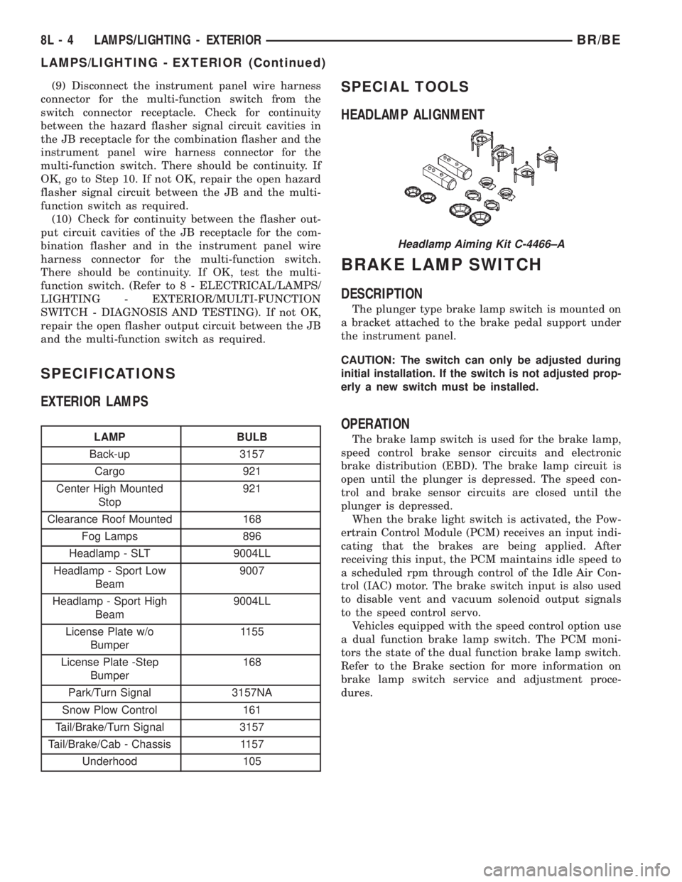
HEADLAMP ALIGNMENT
BRAKE LAMP SWITCH
DESCRIPTION
The plunger type brake lamp switch is mounted on
a bracket attached to the brake pedal support under
the instrument panel.
CAUTION: The switch can only be adjusted during
initial installation. If the switch is not adjusted prop-
erly a new switch must be installed.
OPERATION
The brake lamp switch is used for the brake lamp,
speed control brake sensor circuits and electronic
brake distribution (EBD). The brake lamp circuit is
open until the plunger is depressed. The speed con-
trol and brake sensor circuits are closed until the
plunger is depressed.
When the brake light switch is activated, the Pow-
ertrain Control Module (PCM) receives an input indi-
cating that the brakes are being applied. After
receiving this input, the PCM maintains idle speed to
a scheduled rpm through control of the Idle Air Con-
trol (IAC) motor. The brake switch input is also used
to disable vent and vacuum solenoid output signals
to the speed control servo.
Vehicles equipped with the speed control option use
a dual function brake lamp switch. The PCM moni-
tors the state of the dual function brake lamp switch.
Refer to the Brake section for more information on
brake lamp switch service and adjustment proce-
dures.
Headlamp Aiming Kit C-4466±A
8L - 4 LAMPS/LIGHTING - EXTERIORBR/BE
LAMPS/LIGHTING - EXTERIOR (Continued)
Page 520 of 2255
The brake switch is equipped with three sets of
contacts, one normally open and the other two nor-
mally closed (brakes disengaged). The PCM sends a
12 volt signal to one of the normally closed contacts
in the brake switch, which is returned to the PCM as
a brake switch state signal. With the contacts closed,
the 12 volt signal is pulled to ground causing the sig-
nal to go low. The low voltage signal, monitored by
the PCM, indicates that the brakes are not applied.
When the brakes are applied, the contacts open,
causing the PCM's output brake signal to go high,
disengaging the speed control, cutting off PCM power
to the speed control solenoids.
The second set of normally closed contacts supplies
12 volts from the PCM any time speed control is
turned on. Through the brake switch, current is
routed to the speed control servo solenoids. The
speed control solenoids (vacuum, vent and dump) are
provided this current any time the speed control is
ON and the brakes are disengaged.
When the driver applies the brakes, the contacts
open and current is interrupted to the solenoids. The
normally open contacts are fed battery voltage. When
the brakes are applied, battery voltage is supplied to
the brake lamps.
DIAGNOSIS AND TESTING - BRAKE LAMP
SWITCH
The brake lamp switch can be tested with an ohm-
meter. The ohmmeter is used to check continuity
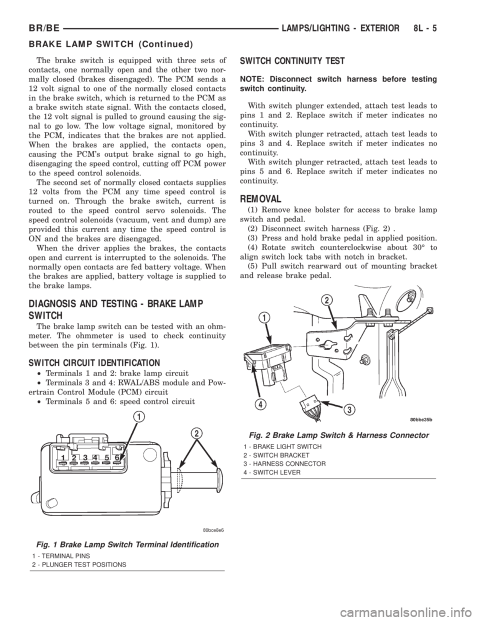
between the pin terminals (Fig. 1).
SWITCH CIRCUIT IDENTIFICATION
²Terminals 1 and 2: brake lamp circuit
²Terminals 3 and 4: RWAL/ABS module and Pow-
ertrain Control Module (PCM) circuit
²Terminals 5 and 6: speed control circuit
SWITCH CONTINUITY TEST
NOTE: Disconnect switch harness before testing
switch continuity.
With switch plunger extended, attach test leads to
pins 1 and 2. Replace switch if meter indicates no
continuity.
With switch plunger retracted, attach test leads to
pins 3 and 4. Replace switch if meter indicates no
continuity.
With switch plunger retracted, attach test leads to
pins 5 and 6. Replace switch if meter indicates no
continuity.
REMOVAL
(1) Remove knee bolster for access to brake lamp
switch and pedal.
(2) Disconnect switch harness (Fig. 2) .
(3) Press and hold brake pedal in applied position.
(4) Rotate switch counterclockwise about 30É to
align switch lock tabs with notch in bracket.
(5) Pull switch rearward out of mounting bracket
and release brake pedal.
Fig. 1 Brake Lamp Switch Terminal Identification
1 - TERMINAL PINS
2 - PLUNGER TEST POSITIONS
Fig. 2 Brake Lamp Switch & Harness Connector
1 - BRAKE LIGHT SWITCH
2 - SWITCH BRACKET
3 - HARNESS CONNECTOR
4 - SWITCH LEVER
BR/BELAMPS/LIGHTING - EXTERIOR 8L - 5
BRAKE LAMP SWITCH (Continued)
Page 521 of 2255
INSTALLATION
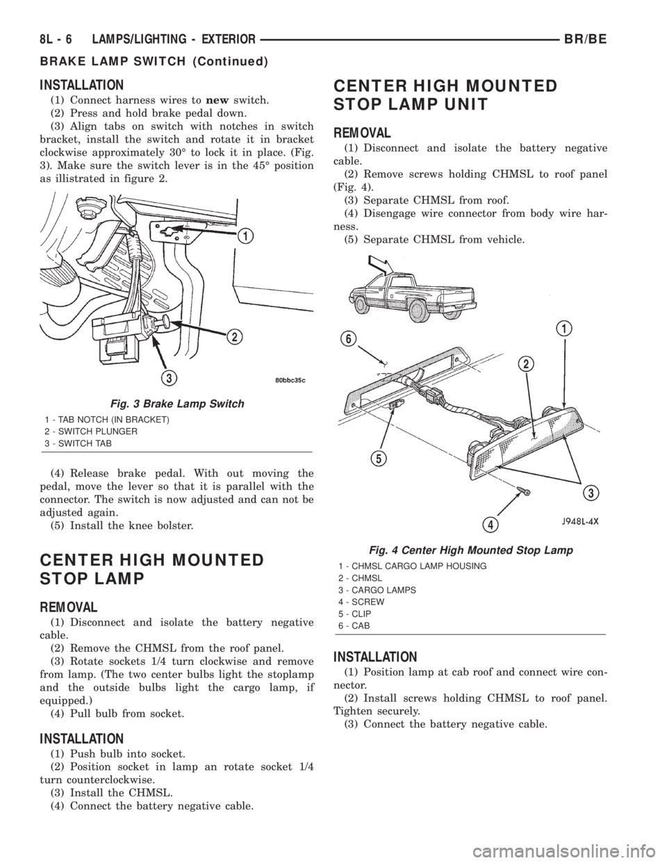
(1) Connect harness wires tonewswitch.
(2) Press and hold brake pedal down.
(3) Align tabs on switch with notches in switch
bracket, install the switch and rotate it in bracket
clockwise approximately 30É to lock it in place. (Fig.
3). Make sure the switch lever is in the 45É position
as illistrated in figure 2.
(4) Release brake pedal. With out moving the
pedal, move the lever so that it is parallel with the
connector. The switch is now adjusted and can not be
adjusted again.
(5) Install the knee bolster.
CENTER HIGH MOUNTED
STOP LAMP
REMOVAL
(1) Disconnect and isolate the battery negative
cable.
(2) Remove the CHMSL from the roof panel.
(3) Rotate sockets 1/4 turn clockwise and remove
from lamp. (The two center bulbs light the stoplamp
and the outside bulbs light the cargo lamp, if
equipped.)
(4) Pull bulb from socket.
INSTALLATION
(1) Push bulb into socket.
(2) Position socket in lamp an rotate socket 1/4
turn counterclockwise.
(3) Install the CHMSL.
(4) Connect the battery negative cable.
CENTER HIGH MOUNTED
STOP LAMP UNIT
REMOVAL
(1) Disconnect and isolate the battery negative
cable.
(2) Remove screws holding CHMSL to roof panel
(Fig. 4).
(3) Separate CHMSL from roof.
(4) Disengage wire connector from body wire har-
ness.
(5) Separate CHMSL from vehicle.
INSTALLATION
(1) Position lamp at cab roof and connect wire con-
nector.
(2) Install screws holding CHMSL to roof panel.
Tighten securely.
(3) Connect the battery negative cable.
Fig. 3 Brake Lamp Switch
1 - TAB NOTCH (IN BRACKET)
2 - SWITCH PLUNGER
3 - SWITCH TAB
Fig. 4 Center High Mounted Stop Lamp
1 - CHMSL CARGO LAMP HOUSING
2 - CHMSL
3 - CARGO LAMPS
4 - SCREW
5 - CLIP
6 - CAB
8L - 6 LAMPS/LIGHTING - EXTERIORBR/BE
BRAKE LAMP SWITCH (Continued)
Page 545 of 2255
(3) Separate lens from lamp.
(4) Grasp bulb, push in slightly and rotate 1/2 turn
counter-clockwise.
PICKUP
(1) Disconnect and isolate the battery negative
cable.
(2) Remove screws from tail lamp.
(3) Grasp lamp, firmly pull lamp rearward to dis-
engage retaining studs.
(4) Remove socket from tail lamp.
(5) Separate tail lamp from cargo box.
(6) Pull bulb from socket.
INSTALLATION
CHASSIS CAB
(1) Install bulb in socket.
(2) Install lamp lens.
(3) Connect the battery negative cable.
PICKUP
(1) Install bulb in socket.
(2) Install socket in tail lamp.
(3) Position tail lamp in cargo box, engage retain-
ing studs and install screws.
(4) Connect the battery negative cable.
TAIL LAMP UNIT
REMOVAL
CAB CHASSIS
(1) Disconnect and isolate the battery negative
cable.
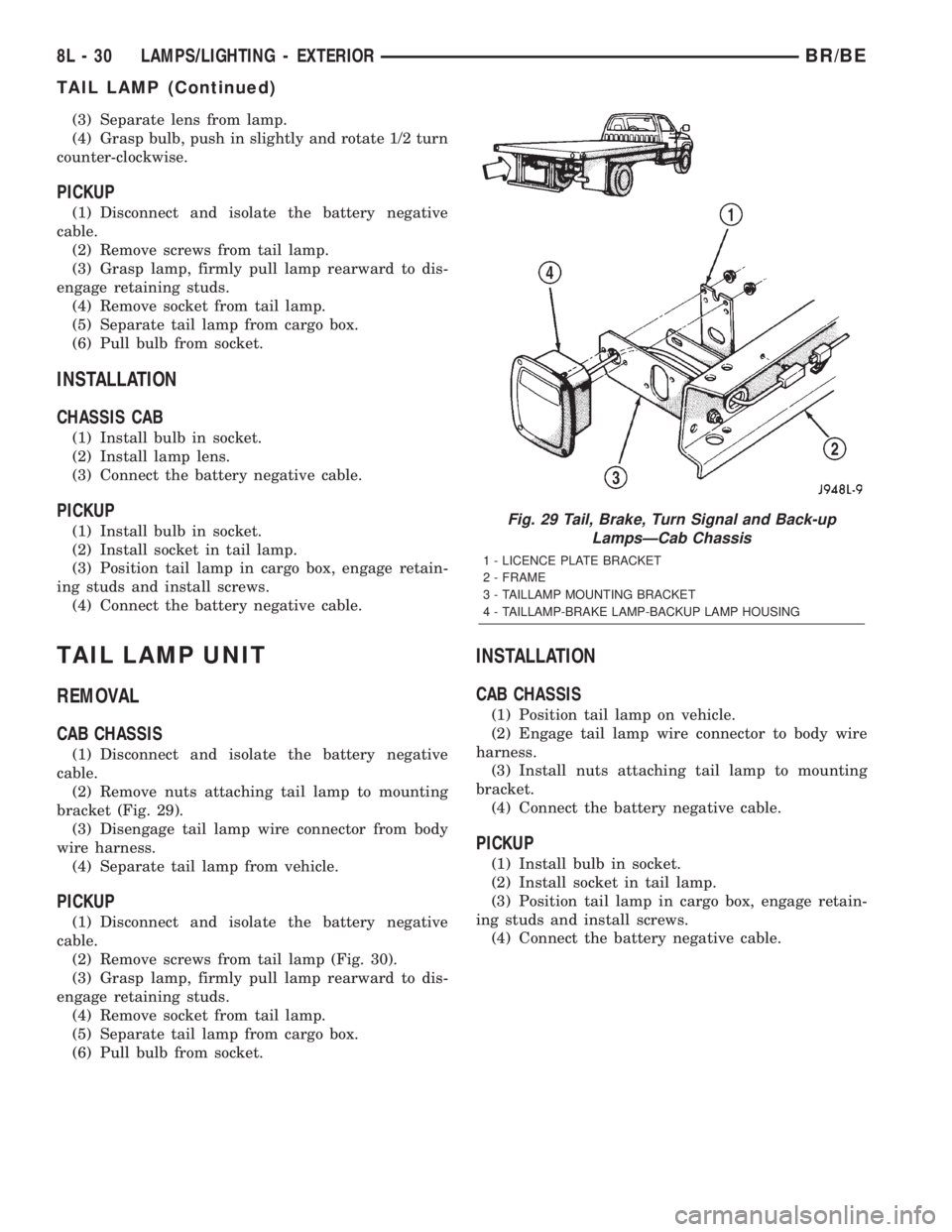
(2) Remove nuts attaching tail lamp to mounting
bracket (Fig. 29).
(3) Disengage tail lamp wire connector from body
wire harness.
(4) Separate tail lamp from vehicle.
PICKUP
(1) Disconnect and isolate the battery negative
cable.
(2) Remove screws from tail lamp (Fig. 30).
(3) Grasp lamp, firmly pull lamp rearward to dis-
engage retaining studs.
(4) Remove socket from tail lamp.
(5) Separate tail lamp from cargo box.
(6) Pull bulb from socket.
INSTALLATION
CAB CHASSIS
(1) Position tail lamp on vehicle.
(2) Engage tail lamp wire connector to body wire
harness.
(3) Install nuts attaching tail lamp to mounting
bracket.
(4) Connect the battery negative cable.
PICKUP
(1) Install bulb in socket.
(2) Install socket in tail lamp.
(3) Position tail lamp in cargo box, engage retain-
ing studs and install screws.
(4) Connect the battery negative cable.
Fig. 29 Tail, Brake, Turn Signal and Back-up
LampsÐCab Chassis
1 - LICENCE PLATE BRACKET
2 - FRAME
3 - TAILLAMP MOUNTING BRACKET
4 - TAILLAMP-BRAKE LAMP-BACKUP LAMP HOUSING
8L - 30 LAMPS/LIGHTING - EXTERIORBR/BE
TAIL LAMP (Continued)