2002 DODGE RAM lock
[x] Cancel search: lockPage 1313 of 2255
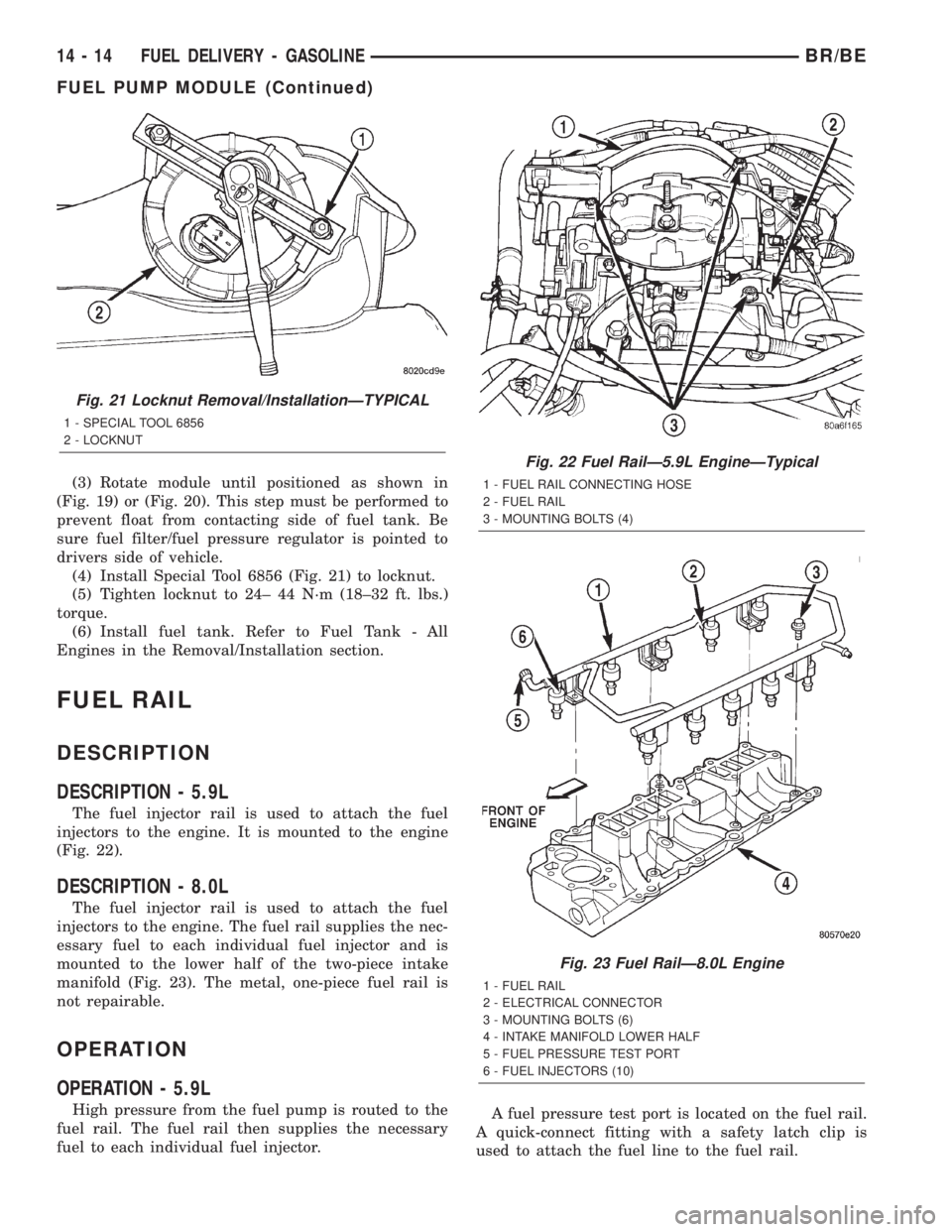
(3) Rotate module until positioned as shown in
(Fig. 19) or (Fig. 20). This step must be performed to
prevent float from contacting side of fuel tank. Be
sure fuel filter/fuel pressure regulator is pointed to
drivers side of vehicle.
(4) Install Special Tool 6856 (Fig. 21) to locknut.
(5) Tighten locknut to 24± 44 N´m (18±32 ft. lbs.)
torque.
(6) Install fuel tank. Refer to Fuel Tank - All
Engines in the Removal/Installation section.
FUEL RAIL
DESCRIPTION
DESCRIPTION - 5.9L
The fuel injector rail is used to attach the fuel
injectors to the engine. It is mounted to the engine
(Fig. 22).
DESCRIPTION - 8.0L
The fuel injector rail is used to attach the fuel
injectors to the engine. The fuel rail supplies the nec-
essary fuel to each individual fuel injector and is
mounted to the lower half of the two-piece intake
manifold (Fig. 23). The metal, one-piece fuel rail is
not repairable.
OPERATION
OPERATION - 5.9L
High pressure from the fuel pump is routed to the
fuel rail. The fuel rail then supplies the necessary
fuel to each individual fuel injector.A fuel pressure test port is located on the fuel rail.
A quick-connect fitting with a safety latch clip is
used to attach the fuel line to the fuel rail.
Fig. 21 Locknut Removal/InstallationÐTYPICAL
1 - SPECIAL TOOL 6856
2 - LOCKNUT
Fig. 22 Fuel RailÐ5.9L EngineÐTypical
1 - FUEL RAIL CONNECTING HOSE
2 - FUEL RAIL
3 - MOUNTING BOLTS (4)
Fig. 23 Fuel RailÐ8.0L Engine
1 - FUEL RAIL
2 - ELECTRICAL CONNECTOR
3 - MOUNTING BOLTS (6)
4 - INTAKE MANIFOLD LOWER HALF
5 - FUEL PRESSURE TEST PORT
6 - FUEL INJECTORS (10)
14 - 14 FUEL DELIVERY - GASOLINEBR/BE
FUEL PUMP MODULE (Continued)
Page 1317 of 2255
(5) Push therightfuel rail down until fuel injec-
tors have bottomed on injector shoulder. Push the
leftfuel rail down until fuel injectors have bottomed
on injector shoulder.
(6) Install fuel rail mounting bolts.
(7) Connect electrical connector to intake manifold
air temperature sensor.
(8) Connect electrical connectors at all fuel injec-
tors. To install connector, refer to (Fig. 26). Push con-
nector onto injector (1) and then push and lock red
colored slider (2). Verify connector is locked to injec-
tor by lightly tugging on connector.
(9) Install the A/C support bracket (if equipped).
(10) Install throttle body to intake manifold. Refer
to Throttle Body installation in this section of the
group.
(11) Install fuel tube (line) at side of fuel rail.
Refer to Quick-Connect Fittings for procedures.
(12) Install air cleaner.
(13) Connect battery cable to battery.
(14) Start engine and check for leaks.
INSTALLATION - 8.0L
(1) Apply a small amount of engine oil to each fuel
injector o-ring. This will help in fuel rail installation.
(2) Install injector(s) and injector clip(s) to fuel
rail.
NOTE: The fuel injector electrical connectors on all
10 injectors should be facing to the right (passen-
ger) side of the vehicle (Fig. 31).
(3) Position the fuel rail/fuel injector assembly to
the injector openings on the intake manifold.
(4) Guide each injector into the intake manifold.
Be careful not to tear the injector o-ring.
(5) Push therightfuel rail down until fuel injec-
tors have bottomed on injector shoulder. Push the
leftfuel rail down until fuel injectors have bottomed
on injector shoulder.
(6) Install the six fuel rail mounting bolts into the
lower half of intake manifold. Tighten bolts to 15
N´m (136 in. lbs.) torque.
(7) Connect electrical connectors at all fuel injec-
tors. To install connector, refer to (Fig. 30). Push con-
nector onto injector (1) and then push and lock red
colored slider (2). Verify connector is locked to injec-
tor by lightly tugging on connector. The injector wir-
ing harness is numerically tagged.
(8) Install upper half of intake manifold. Refer to
Engines for procedures.
(9) Connect main fuel line at fuel rail. Refer to
Quick-Connect Fittings for procedures.
(10) Install ignition coil pack and bracket assem-
bly at intake manifold and right engine valve cover
(four bolts).(11) Install throttle body to intake manifold. Refer
to Throttle Body removal in this group.
(12) Install throttle body linkage to throttle body.
(13) Install air cleaner tube and housing.
(14) Install negative battery cable at battery.
(15) Start engine and check for leaks.
FUEL TANK
DESCRIPTION
The fuel tank is constructed of a plastic material.
Its main functions are for fuel storage and for place-
ment of the fuel pump module.
OPERATION
All models pass a full 360 degree rollover test
without fuel leakage. To accomplish this, fuel and
vapor flow controls are required for all fuel tank con-
nections.
A fuel tank check valve(s) is mounted into the top
of the fuel tank (or pump module). Refer to Emission
Control System for fuel tank check valve information.
An evaporation control system is connected to the
rollover valve(s) to reduce emissions of fuel vapors
into the atmosphere. When fuel evaporates from the
fuel tank, vapors pass through vent hoses or tubes to
a charcoal canister where they are temporarily held.
When the engine is running, the vapors are drawn
into the intake manifold. Certain models are also
equipped with a self-diagnosing system using a Leak
Detection Pump (LDP). Refer to Emission Control
System for additional information.
REMOVAL
WARNING: GASOLINE POWERED ENGINES: THE
FUEL SYSTEM IS UNDER A CONSTANT PRESSURE
EVEN WITH THE ENGINE OFF. BEFORE SERVICING
THE FUEL TANK, FUEL SYSTEM PRESSURE MUST
BE RELEASED. REFER TO THE FUEL SYSTEM
PRESSURE RELEASE PROCEDURE BEFORE SER-
VICING THE FUEL TANK.
Two different procedures may be used to drain fuel
tank (lowering tank or using DRB scan tool). When
equipped with a diesel engine, the DRB scan tool
cannot be used (no electric fuel pump).
The quickest draining procedure involves lowering
the fuel tank.
Gasoline Powered Engines:As an alternative
procedure, the electric fuel pump may be activated
allowing tank to be drained at fuel rail connection.
Refer to DRB scan tool for fuel pump activation pro-
cedures. Before disconnecting fuel line at fuel rail,
release fuel pressure. Refer to the Fuel System Pres-
sure Release Procedure in this group for procedures.
14 - 18 FUEL DELIVERY - GASOLINEBR/BE
FUEL RAIL (Continued)
Page 1319 of 2255
INSTALLATION
(1) Gasoline Engines: If fuel pump module is being
installed, refer to Fuel Pump Module Removal/Instal-
lation in this group. Diesel Engines: If fuel tank mod-
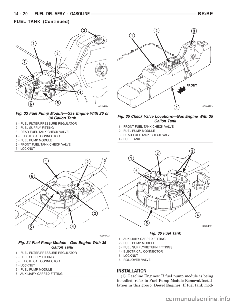
Fig. 33 Fuel Pump ModuleÐGas Engine With 26 or
34 Gallon Tank
1 - FUEL FILTER/PRESSURE REGULATOR
2 - FUEL SUPPLY FITTING
3 - REAR FUEL TANK CHECK VALVE
4 - ELECTRICAL CONNECTOR
5 - FUEL PUMP MODULE
6 - FRONT FUEL TANK CHECK VALVE
7 - LOCKNUT
Fig. 34 Fuel Pump ModuleÐGas Engine With 35
Gallon Tank
1 - FUEL FILTER/PRESSURE REGULATOR
2 - FUEL SUPPLY FITTING
3 - ELECTRICAL CONNECTOR
4 - LOCKNUT
5 - FUEL PUMP MODULE
6 - AUXILIARY CAPPED FITTING
Fig. 35 Check Valve LocationsÐGas Engine With 35
Gallon Tank
1 - FRONT FUEL TANK CHECK VALVE
2 - FUEL PUMP MODULE
3 - REAR FUEL TANK CHECK VALVE
4 - FUEL TANK
Fig. 36 Fuel Tank
1 - AUXILIARY CAPPED FITTING
2 - FUEL PUMP MODULE
3 - FUEL SUPPLY/RETURN FITTINGS
4 - ELECTRICAL CONNECTOR
5 - LOCKNUT
6 - ROLLOVER VALVE
14 - 20 FUEL DELIVERY - GASOLINEBR/BE
FUEL TANK (Continued)
Page 1320 of 2255
ule is being installed, refer to Fuel Tank Module
Removal/Installation in this group.
(2) Place fuel tank on top of transmission jack.
(3) Install rubber fill and vent lines to tank.
Tighten hose clamps to 2.3 N´m (20 in. lbs.) torque.
(4) Raise tank into position while guiding fill and
vent hoses to body. Raise tank only enough to allow
access to top of tank.
(5)Gas Powered Engines:
(a) Connect electrical connector to fuel pump
module.
(b) Connect EVAP hoses at rollover valves.
(c) Connect fuel supply line at fuel filter/fuel
pressure regulator. Refer to Quick-Connect Fittings
for procedures.
(6)Diesel Powered Engines:
(a) Connect electrical connector to fuel tank
module.
(b) Connect fuel supply and fuel return lines to
fuel tank module fittings. Refer to Quick-Connect
Fittings in this group.
(7) Connect two mounting straps and mounting
strap nuts.
(8) Tighten strap nuts to 41 N´m (30 ft. lbs.)
torque. Do not over tighten retaining strap nuts.
(9) Remove transmission jack.
(10) Connect fuel filler tube assembly to body.
(11) If equipped, connect grounding wire (strap)
and screw.
(12) Refill fuel tank and inspect all hoses and lines
for leaks.
(13) Connect negative battery cable(s) to bat-
tery(s).
FUEL TANK CHECK VALVE
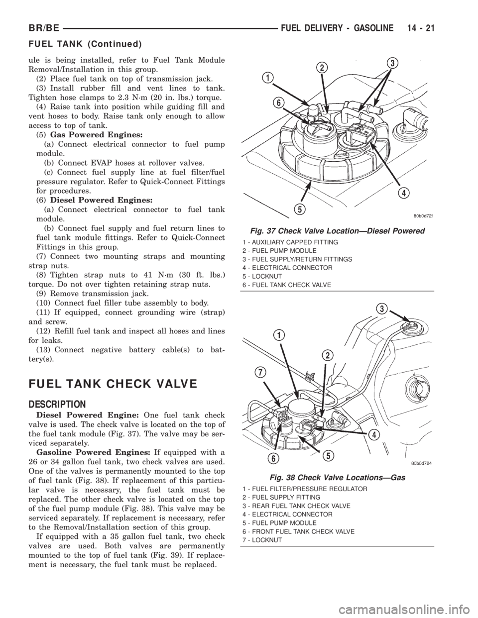
DESCRIPTION
Diesel Powered Engine:One fuel tank check
valve is used. The check valve is located on the top of
the fuel tank module (Fig. 37). The valve may be ser-
viced separately.
Gasoline Powered Engines:If equipped with a
26 or 34 gallon fuel tank, two check valves are used.
One of the valves is permanently mounted to the top
of fuel tank (Fig. 38). If replacement of this particu-
lar valve is necessary, the fuel tank must be
replaced. The other check valve is located on the top
of the fuel pump module (Fig. 38). This valve may be
serviced separately. If replacement is necessary, refer
to the Removal/Installation section of this group.
If equipped with a 35 gallon fuel tank, two check
valves are used. Both valves are permanently
mounted to the top of fuel tank (Fig. 39). If replace-
ment is necessary, the fuel tank must be replaced.
Fig. 37 Check Valve LocationÐDiesel Powered
1 - AUXILIARY CAPPED FITTING
2 - FUEL PUMP MODULE
3 - FUEL SUPPLY/RETURN FITTINGS
4 - ELECTRICAL CONNECTOR
5 - LOCKNUT
6 - FUEL TANK CHECK VALVE
Fig. 38 Check Valve LocationsÐGas
1 - FUEL FILTER/PRESSURE REGULATOR
2 - FUEL SUPPLY FITTING
3 - REAR FUEL TANK CHECK VALVE
4 - ELECTRICAL CONNECTOR
5 - FUEL PUMP MODULE
6 - FRONT FUEL TANK CHECK VALVE
7 - LOCKNUT
BR/BEFUEL DELIVERY - GASOLINE 14 - 21
FUEL TANK (Continued)
Page 1321 of 2255
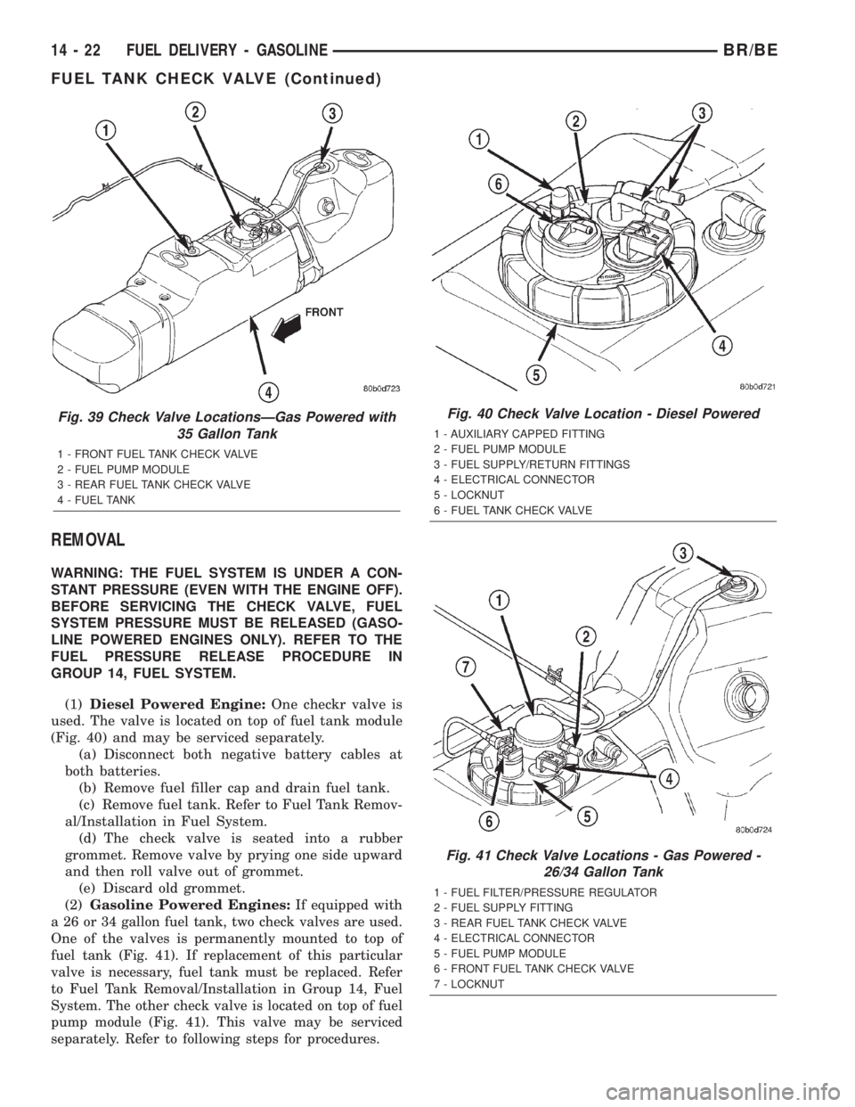
REMOVAL
WARNING: THE FUEL SYSTEM IS UNDER A CON-
STANT PRESSURE (EVEN WITH THE ENGINE OFF).
BEFORE SERVICING THE CHECK VALVE, FUEL
SYSTEM PRESSURE MUST BE RELEASED (GASO-
LINE POWERED ENGINES ONLY). REFER TO THE
FUEL PRESSURE RELEASE PROCEDURE IN
GROUP 14, FUEL SYSTEM.
(1)Diesel Powered Engine:One checkr valve is
used. The valve is located on top of fuel tank module
(Fig. 40) and may be serviced separately.
(a) Disconnect both negative battery cables at
both batteries.
(b) Remove fuel filler cap and drain fuel tank.
(c) Remove fuel tank. Refer to Fuel Tank Remov-
al/Installation in Fuel System.
(d) The check valve is seated into a rubber
grommet. Remove valve by prying one side upward
and then roll valve out of grommet.
(e) Discard old grommet.
(2)Gasoline Powered Engines:
If equipped with
a 26 or 34 gallon fuel tank, two check valves are used.
One of the valves is permanently mounted to top of
fuel tank (Fig. 41). If replacement of this particular
valve is necessary, fuel tank must be replaced. Refer
to Fuel Tank Removal/Installation in Group 14, Fuel
System. The other check valve is located on top of fuel
pump module (Fig. 41). This valve may be serviced
separately. Refer to following steps for procedures.
Fig. 39 Check Valve LocationsÐGas Powered with
35 Gallon Tank
1 - FRONT FUEL TANK CHECK VALVE
2 - FUEL PUMP MODULE
3 - REAR FUEL TANK CHECK VALVE
4 - FUEL TANK
Fig. 40 Check Valve Location - Diesel Powered
1 - AUXILIARY CAPPED FITTING
2 - FUEL PUMP MODULE
3 - FUEL SUPPLY/RETURN FITTINGS
4 - ELECTRICAL CONNECTOR
5 - LOCKNUT
6 - FUEL TANK CHECK VALVE
Fig. 41 Check Valve Locations - Gas Powered -
26/34 Gallon Tank
1 - FUEL FILTER/PRESSURE REGULATOR
2 - FUEL SUPPLY FITTING
3 - REAR FUEL TANK CHECK VALVE
4 - ELECTRICAL CONNECTOR
5 - FUEL PUMP MODULE
6 - FRONT FUEL TANK CHECK VALVE
7 - LOCKNUT
14 - 22 FUEL DELIVERY - GASOLINEBR/BE
FUEL TANK CHECK VALVE (Continued)
Page 1322 of 2255
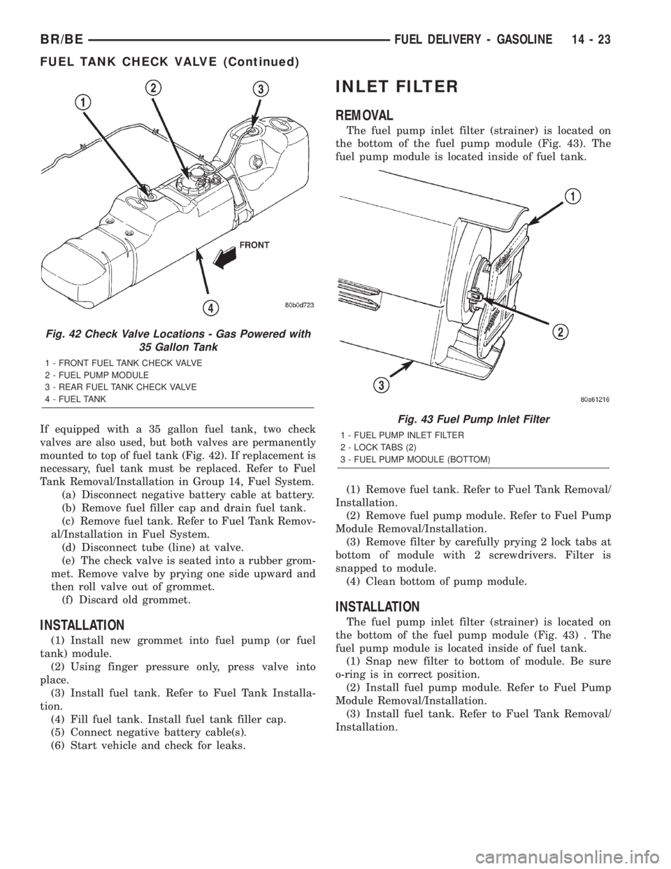
If equipped with a 35 gallon fuel tank, two check
valves are also used, but both valves are permanently
mounted to top of fuel tank (Fig. 42). If replacement is
necessary, fuel tank must be replaced. Refer to Fuel
Tank Removal/Installation in Group 14, Fuel System.
(a) Disconnect negative battery cable at battery.
(b) Remove fuel filler cap and drain fuel tank.
(c) Remove fuel tank. Refer to Fuel Tank Remov-
al/Installation in Fuel System.
(d) Disconnect tube (line) at valve.
(e) The check valve is seated into a rubber grom-
met. Remove valve by prying one side upward and
then roll valve out of grommet.
(f) Discard old grommet.
INSTALLATION
(1) Install new grommet into fuel pump (or fuel
tank) module.
(2) Using finger pressure only, press valve into
place.
(3) Install fuel tank. Refer to Fuel Tank Installa-
tion.
(4) Fill fuel tank. Install fuel tank filler cap.
(5) Connect negative battery cable(s).
(6) Start vehicle and check for leaks.
INLET FILTER
REMOVAL
The fuel pump inlet filter (strainer) is located on
the bottom of the fuel pump module (Fig. 43). The
fuel pump module is located inside of fuel tank.
(1) Remove fuel tank. Refer to Fuel Tank Removal/
Installation.
(2) Remove fuel pump module. Refer to Fuel Pump
Module Removal/Installation.
(3) Remove filter by carefully prying 2 lock tabs at
bottom of module with 2 screwdrivers. Filter is
snapped to module.
(4) Clean bottom of pump module.
INSTALLATION
The fuel pump inlet filter (strainer) is located on
the bottom of the fuel pump module (Fig. 43) . The
fuel pump module is located inside of fuel tank.
(1) Snap new filter to bottom of module. Be sure
o-ring is in correct position.
(2) Install fuel pump module. Refer to Fuel Pump
Module Removal/Installation.
(3) Install fuel tank. Refer to Fuel Tank Removal/
Installation.
Fig. 42 Check Valve Locations - Gas Powered with
35 Gallon Tank
1 - FRONT FUEL TANK CHECK VALVE
2 - FUEL PUMP MODULE
3 - REAR FUEL TANK CHECK VALVE
4 - FUEL TANK
Fig. 43 Fuel Pump Inlet Filter
1 - FUEL PUMP INLET FILTER
2 - LOCK TABS (2)
3 - FUEL PUMP MODULE (BOTTOM)
BR/BEFUEL DELIVERY - GASOLINE 14 - 23
FUEL TANK CHECK VALVE (Continued)
Page 1326 of 2255
(8)Latch Clips:Depending on vehicle model and
engine, 2 different types of safety latch clips are used
(Fig. 50) or (Fig. 51). Type-1 is tethered to fuel line
and type-2 is not. A special tool will be necessary to
disconnect fuel line after latch clip is removed. The
latch clip may be used on certain fuel line/fuel rail
connection, or to join fuel lines together.
(a) Type 1: Pry up on latch clip with a screw-
driver (Fig. 50).
(b) Type 2: Separate and unlatch 2 small arms
on end of clip (Fig. 51) and swing away from fuel
line.
(c) Slide latch clip toward fuel rail while lifting
with screwdriver.
(d) Insert special fuel line removal tool (Snap-On
number FIH 9055-1 or equivalent) into fuel line
(Fig. 52). Use tool to release locking fingers in end
of line.
(e) With special tool still inserted, pull fuel line
from fuel rail.
(f) After disconnection, locking fingers will
remain within quick-connect fitting at end of fuel
line.
(9) Disconnect quick-connect fitting from fuel sys-
tem component being serviced.CONNECTING
(1) Inspect quick-connect fitting body and fuel sys-
tem component for damage. Replace as necessary.
(2) Prior to connecting quick-connect fitting to
component being serviced, check condition of fitting
and component. Clean parts with a lint-free cloth.
Lubricate with clean engine oil.
(3) Insert quick-connect fitting into fuel tube or
fuel system component until built-on stop on fuel
tube or component rests against back of fitting.
(4) Continue pushing until a click is felt.
(5) Single-tab type fitting: Push new tab down
until it locks into place in quick-connect fitting.
(6) Verify a locked condition by firmly pulling on
fuel tube and fitting (15-30 lbs.).
(7) Latch Clip Equipped: Install latch clip (snaps
into position).If latch clip will not fit, this indi-
cates fuel line is not properly installed to fuel
rail (or other fuel line). Recheck fuel line con-
nection.
(8) Connect negative cable to battery.
(9) Start engine and check for leaks.
BR/BEFUEL DELIVERY - GASOLINE 14 - 27
QUICK CONNECT FITTING (Continued)
Page 1330 of 2255
(22) Inspect for pinched or leaking fuel tubes.
Inspect for pinched, cracked or leaking fuel hoses.
(23) Inspect for exhaust system restrictions such
as pinched exhaust pipes, collapsed muffler or
plugged catalytic convertor.
(24) If equipped with automatic transmission, ver-
ify that electrical harness is firmly connected to park/
neutral switch. Refer to 21, Automatic Transmission.(25) Verify electrical harness is firmly connected to
rear wheel speed sensor. Verify rear wheel speed sen-
sor is firmly attached to rear axle with proper air
gap. Refer to 5, Brakes for information.
(26) If equipped with 4±wheel antilock brake sys-
tem, verify electrical harness is firmly connected to
each front wheel speed sensor. Verify both front
wheel speed sensors are firmly attached. Refer to 5,
Brakes for information.
(27) Verify that fuel pump/gauge sender unit wire
connector is firmly connected to harness connector.
(28) Inspect fuel hoses at fuel pump/gauge sender
unit for cracks or leaks.
Fig. 7 Rubber L-Shaped FittingÐMAP Sensor-to-
Throttle BodyÐ5.9L Engines
1 - MAP SENSOR
2 - RUBBER FITTING
3 - IDLE AIR PASSAGE
Fig. 8 Engine Coolant Temperature
1 - GENERATOR
2 - A/C COMPRESSOR
3 - ENGINE COOLANT TEMPERATURE SENSOR
4 - ELEC. CONN.
Fig. 9 Left/Right Oxygen SensorsÐHDC Engines
1 - DUAL OXYGEN SENSORS
2 - TOP OF TRANSMISSION
Fig. 10 Pre-Catalyst/Post-Catalyst Sensors
1 - POST CATALYST OXYGEN SENSOR (1/3)
2 - PRE-CATALYST OXYGEN SENSOR (1/2)
BR/BEFUEL INJECTION - GASOLINE 14 - 31
FUEL INJECTION - GASOLINE (Continued)