2002 DODGE RAM lock
[x] Cancel search: lockPage 1265 of 2255
(8) Remove viscous fan/drive assembly (Refer to 7 -
COOLING/ENGINE/RADIATOR FAN - REMOVAL).
(9) Remove the accessory drive belt (Refer to 7 -
COOLING/ACCESSORY DRIVE/DRIVE BELTS -
REMOVAL).
(10) Remove the cooling fan support/hub from the
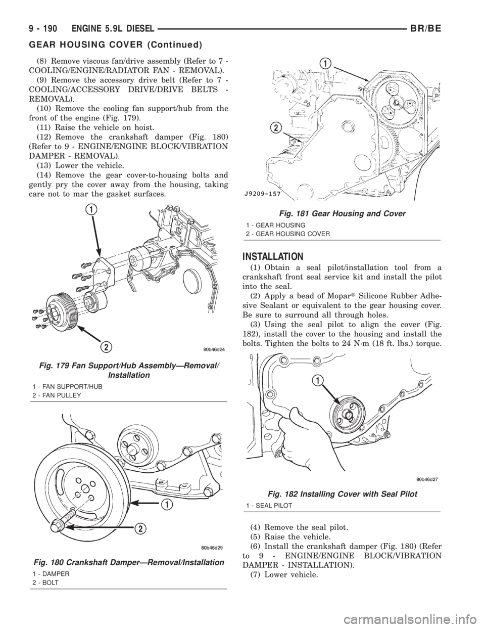
front of the engine (Fig. 179).
(11) Raise the vehicle on hoist.
(12) Remove the crankshaft damper (Fig. 180)
(Refer to 9 - ENGINE/ENGINE BLOCK/VIBRATION
DAMPER - REMOVAL).
(13) Lower the vehicle.
(14) Remove the gear cover-to-housing bolts and
gently pry the cover away from the housing, taking
care not to mar the gasket surfaces.
INSTALLATION
(1) Obtain a seal pilot/installation tool from a
crankshaft front seal service kit and install the pilot
into the seal.
(2) Apply a bead of MopartSilicone Rubber Adhe-
sive Sealant or equivalent to the gear housing cover.
Be sure to surround all through holes.
(3) Using the seal pilot to align the cover (Fig.
182), install the cover to the housing and install the
bolts. Tighten the bolts to 24 N´m (18 ft. lbs.) torque.
(4) Remove the seal pilot.
(5) Raise the vehicle.
(6) Install the crankshaft damper (Fig. 180) (Refer
to 9 - ENGINE/ENGINE BLOCK/VIBRATION
DAMPER - INSTALLATION).
(7) Lower vehicle.
Fig. 179 Fan Support/Hub AssemblyÐRemoval/
Installation
1 - FAN SUPPORT/HUB
2 - FAN PULLEY
Fig. 180 Crankshaft DamperÐRemoval/Installation
1 - DAMPER
2 - BOLT
Fig. 181 Gear Housing and Cover
1 - GEAR HOUSING
2 - GEAR HOUSING COVER
Fig. 182 Installing Cover with Seal Pilot
1 - SEAL PILOT
9 - 190 ENGINE 5.9L DIESELBR/BE
GEAR HOUSING COVER (Continued)
Page 1295 of 2255
FRAME FASTENERS
Bolts, nuts and rivets can be used to repair frames
or to install a reinforcement section on the frame.
Bolts can be used in place of rivets. When replacing
rivets with bolts, install the next larger size diameter
bolt to assure proper fit. If necessary, ream the hole
out just enough to sufficiently receive the bolt.
Conical-type washers are preferred over the split-
ring type lock washers. Normally, grade-5 bolts are
adequate for frame repair.Grade-3 bolts or softer
should not be used.Tightening bolts/nuts with thecorrect torque, refer to the Introduction Group at the
front of this manual for tightening information.
SPECIFICATIONS
FRAME DIMENSION
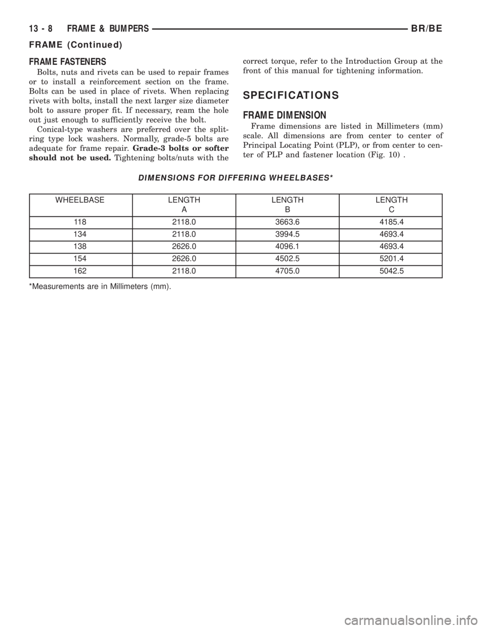
Frame dimensions are listed in Millimeters (mm)
scale. All dimensions are from center to center of
Principal Locating Point (PLP), or from center to cen-
ter of PLP and fastener location (Fig. 10) .
DIMENSIONS FOR DIFFERING WHEELBASES*
WHEELBASE LENGTH
ALENGTH
BLENGTH
C
118 2118.0 3663.6 4185.4
134 2118.0 3994.5 4693.4
138 2626.0 4096.1 4693.4
154 2626.0 4502.5 5201.4
162 2118.0 4705.0 5042.5
*Measurements are in Millimeters (mm).
13 - 8 FRAME & BUMPERSBR/BE
FRAME (Continued)
Page 1301 of 2255
FUEL DELIVERY - GASOLINE
DESCRIPTION - FUEL DELIVERY SYSTEM
The fuel delivery system consists of:
²the fuel pump module containing the electric
fuel pump, fuel filter/fuel pressure regulator, rollover
valve (certain modules), fuel gauge sending unit (fuel
level sensor) and a separate fuel filter located at bot-
tom of pump module
²fuel tubes/lines/hoses
²quick-connect fittings
²fuel injector rail
²fuel injectors
²fuel tank
²fuel tank filler/vent tube assembly
²fuel tank filler tube cap
²accelerator pedal
²throttle cable
OPERATION - FUEL DELIVERY SYSTEM
Fuel is returned through the fuel pump module
and back into the fuel tank through the fuel filter/
fuel pressure regulator. A separate fuel return line
from the engine to the tank is not used with any gas-
oline powered engine.
The fuel tank assembly consists of: the fuel tank,
fuel pump module assembly, fuel pump module lock-
nut/gasket and fuel tank check valve(s) (refer to 25,
Emission Control System for Fuel Tank Check Valve
information).
A fuel filler/vent tube assembly using a pressure/
vacuum, 1/4 turn fuel filler cap is used. The fuel
filler tube contains a flap door located below the fuel
fill cap.
Also to be considered part of the fuel system is the
evaporation control system. This is designed to
reduce the emission of fuel vapors into the atmo-
sphere. The description and function of the Evapora-
tive Control System is found in 25, Emission Control
Systems.
Both fuel filters (at bottom of fuel pump module
and within fuel pressure regulator) are designed for
extended service. They do not require normal sched-
uled maintenance. Filters should only be replaced if
a diagnostic procedure indicates to do so.
DIAGNOSIS AND TESTING - FUEL PRESSURE
LEAK DOWN TEST
Use this test in conjunction with the Fuel Pump
Pressure Test and Fuel Pump Capacity Test.
Check Valve Operation:The electric fuel pump
outlet contains a one-way check valve to prevent fuel
flow back into the tank and to maintain fuel supply
line pressure (engine warm) when pump is not oper-
ational. It is also used to keep the fuel supply linefull of gasoline when pump is not operational. After
the vehicle has cooled down, fuel pressure may drop
to 0 psi (cold fluid contracts), but liquid gasoline will
remain in fuel supply line between the check valve
and fuel injectors.Fuel pressure that has
dropped to 0 psi on a cooled down vehicle
(engine off) is a normal condition.When the elec-
tric fuel pump is activated, fuel pressure should
immediately(1±2 seconds) rise to specification.
Abnormally long periods of cranking to restart a
hotengine that has been shut down for a short
period of time may be caused by:
²Fuel pressure bleeding past a fuel injector(s).
²Fuel pressure bleeding past the check valve in
the fuel pump module.
(1) Disconnect the fuel inlet line at fuel rail. Refer
to Fuel Tubes/Lines/Hoses and Clamps for proce-
dures. On some engines, air cleaner housing removal
may be necessary before fuel line disconnection.
(2) Obtain correct Fuel Line Pressure Test Adapter
Tool Hose. Tool number 6539 is used for 5/16º fuel
lines and tool number 6631 is used for 3/8º fuel lines.
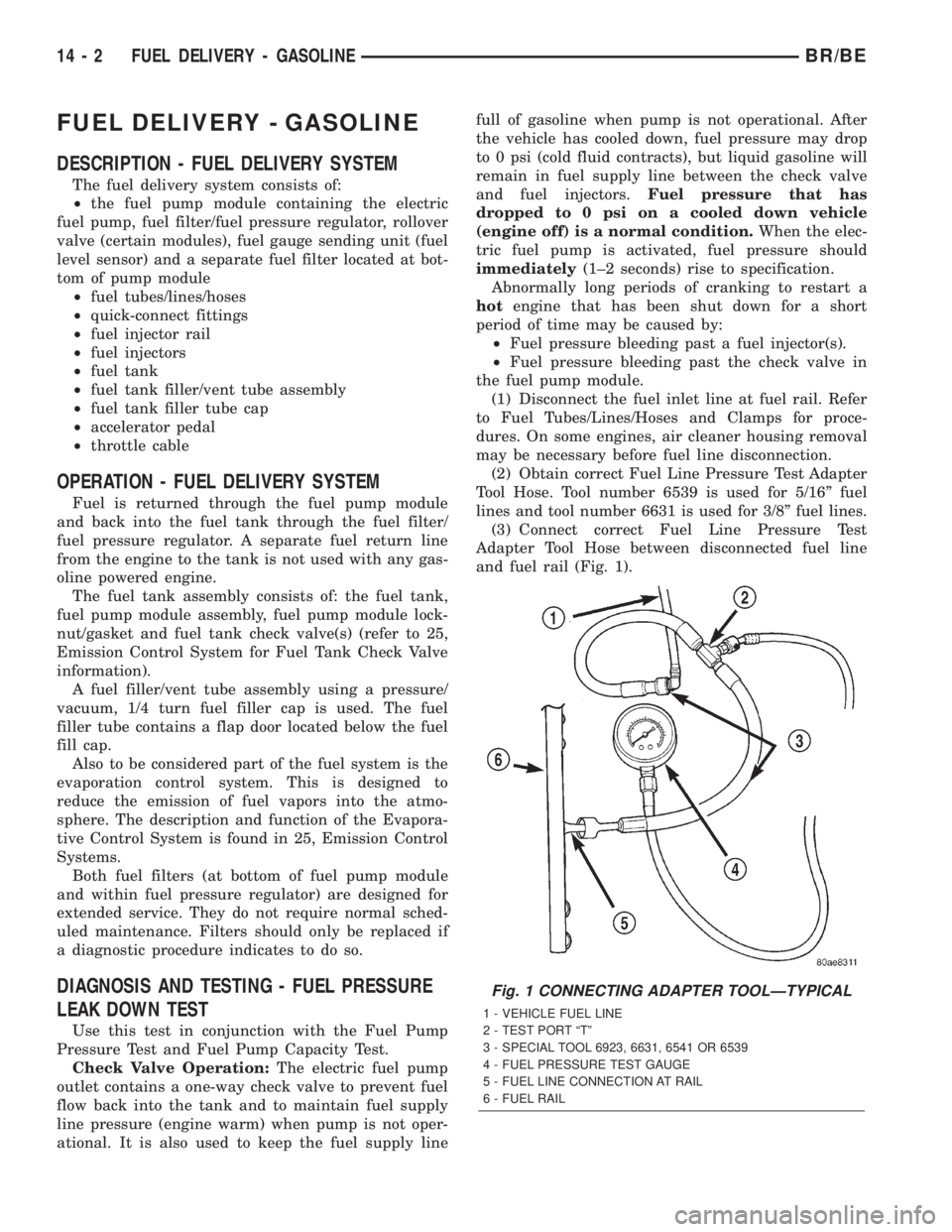
(3) Connect correct Fuel Line Pressure Test
Adapter Tool Hose between disconnected fuel line
and fuel rail (Fig. 1).
Fig. 1 CONNECTING ADAPTER TOOLÐTYPICAL
1 - VEHICLE FUEL LINE
2 - TEST PORT ªTº
3 - SPECIAL TOOL 6923, 6631, 6541 OR 6539
4 - FUEL PRESSURE TEST GAUGE
5 - FUEL LINE CONNECTION AT RAIL
6 - FUEL RAIL
14 - 2 FUEL DELIVERY - GASOLINEBR/BE
Page 1303 of 2255
SPECIFICATIONS - TORQUE - FUEL DELIVERY
DESCRIPTION N´m Ft. Lbs. In. Lbs.
Fuel Pump Module Locknut 24-44 18-32
Fuel Rail Mounting BoltsÐ5.9L Engines 23 200
Fuel Rail Mounting BoltsÐ8.0L Engine 15 136
Fuel Tank Mounting Nuts 41 30
Fuel Hose Clamps 1 15
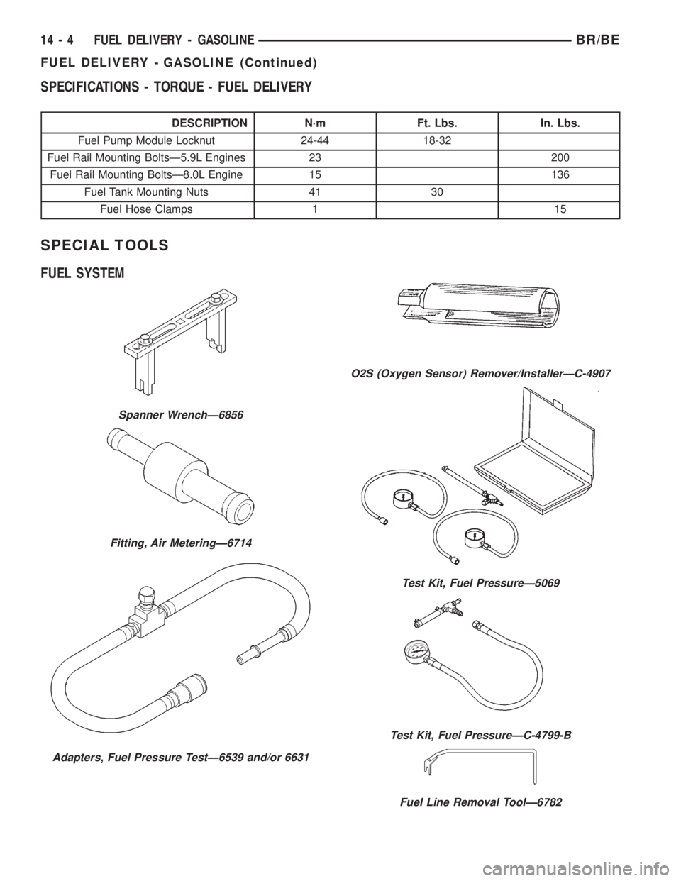
SPECIAL TOOLS
FUEL SYSTEM
Spanner WrenchÐ6856
Fitting, Air MeteringÐ6714
Adapters, Fuel Pressure TestÐ6539 and/or 6631
O2S (Oxygen Sensor) Remover/InstallerÐC-4907
Test Kit, Fuel PressureÐ5069
Test Kit, Fuel PressureÐC-4799-B
Fuel Line Removal ToolÐ6782
14 - 4 FUEL DELIVERY - GASOLINEBR/BE
FUEL DELIVERY - GASOLINE (Continued)
Page 1305 of 2255

(2) The fuel filter/regulator is pressed into a rub-
ber grommet. Remove by twisting and pulling
straight up (Fig. 6).
CAUTION: Do not pull filter/regulator more than
three inches from fuel pump module. Damage to
coiled fuel tube (line) may result.
(3) Gently cut old fuel tube (line) clamp (Fig. 7)
taking care not to damage plastic fuel tube. Remove
and discard old fuel tube clamp.
(4) Remove plastic fuel tube from filter/regulator
by gently pulling downward. Remove filter/regulator
from fuel pump module.
Fig. 4 Filter/Regulator LocationÐWith 26 or 34
Gallon Fuel Tank
1 - FUEL FILTER/PRESSURE REGULATOR
2 - FUEL SUPPLY FITTING
3 - REAR FUEL TANK CHECK VALVE
4 - ELECTRICAL CONNECTOR
5 - FUEL PUMP MODULE
6 - FRONT FUEL TANK CHECK VALVE
7 - LOCKNUT
Fig. 5 Filter/Regulator LocationÐWith 35 Gallon
Fuel Tank
1 - FUEL FILTER/PRESSURE REGULATOR
2 - FUEL SUPPLY FITTING
3 - ELECTRICAL CONNECTOR
4 - LOCKNUT
5 - FUEL PUMP MODULE
6 - AUXILIARY CAPPED FITTING
Fig. 6 Filter/Regulator Removal and InstallationÐ
TYPICAL
1 - RUBBER GROMMET
2 - FUEL FILTER/FUEL PRESSURE REGULATOR
Fig. 7 Fuel Tube and ClampÐTYPICAL
1 - FUEL FILTER/FUEL PRESSURE REGULATOR
2 - TUBE CLAMP
3 - FUEL TUBE
14 - 6 FUEL DELIVERY - GASOLINEBR/BE
FUEL FILTER/PRESSURE REGULATOR (Continued)
Page 1307 of 2255
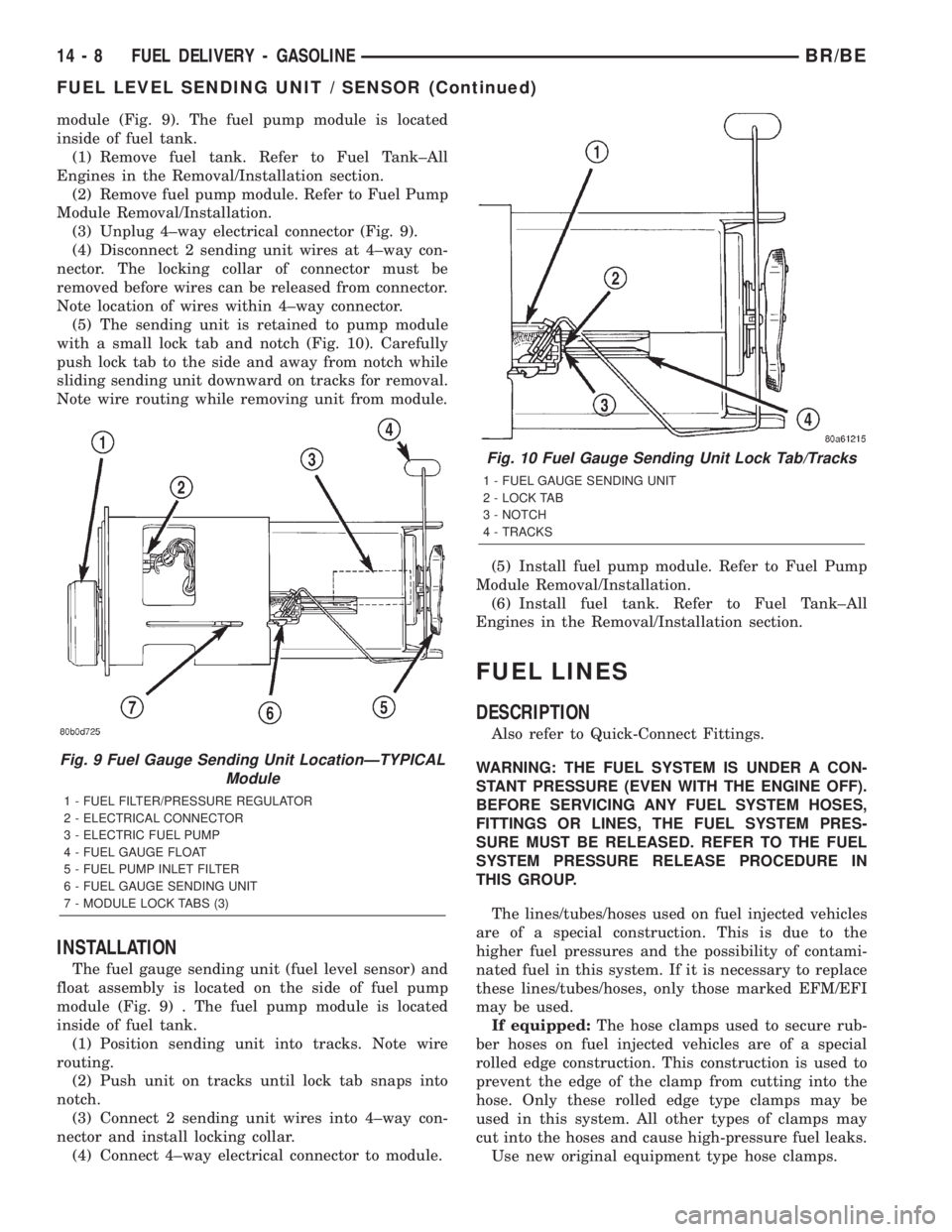
module (Fig. 9). The fuel pump module is located
inside of fuel tank.
(1) Remove fuel tank. Refer to Fuel Tank±All
Engines in the Removal/Installation section.
(2) Remove fuel pump module. Refer to Fuel Pump
Module Removal/Installation.
(3) Unplug 4±way electrical connector (Fig. 9).
(4) Disconnect 2 sending unit wires at 4±way con-
nector. The locking collar of connector must be
removed before wires can be released from connector.
Note location of wires within 4±way connector.
(5) The sending unit is retained to pump module
with a small lock tab and notch (Fig. 10). Carefully
push lock tab to the side and away from notch while
sliding sending unit downward on tracks for removal.
Note wire routing while removing unit from module.
INSTALLATION
The fuel gauge sending unit (fuel level sensor) and
float assembly is located on the side of fuel pump
module (Fig. 9) . The fuel pump module is located
inside of fuel tank.
(1) Position sending unit into tracks. Note wire
routing.
(2) Push unit on tracks until lock tab snaps into
notch.
(3) Connect 2 sending unit wires into 4±way con-
nector and install locking collar.
(4) Connect 4±way electrical connector to module.(5) Install fuel pump module. Refer to Fuel Pump
Module Removal/Installation.
(6) Install fuel tank. Refer to Fuel Tank±All
Engines in the Removal/Installation section.
FUEL LINES
DESCRIPTION
Also refer to Quick-Connect Fittings.
WARNING: THE FUEL SYSTEM IS UNDER A CON-
STANT PRESSURE (EVEN WITH THE ENGINE OFF).
BEFORE SERVICING ANY FUEL SYSTEM HOSES,
FITTINGS OR LINES, THE FUEL SYSTEM PRES-
SURE MUST BE RELEASED. REFER TO THE FUEL
SYSTEM PRESSURE RELEASE PROCEDURE IN
THIS GROUP.
The lines/tubes/hoses used on fuel injected vehicles
are of a special construction. This is due to the
higher fuel pressures and the possibility of contami-
nated fuel in this system. If it is necessary to replace
these lines/tubes/hoses, only those marked EFM/EFI
may be used.
If equipped:The hose clamps used to secure rub-
ber hoses on fuel injected vehicles are of a special
rolled edge construction. This construction is used to
prevent the edge of the clamp from cutting into the
hose. Only these rolled edge type clamps may be
used in this system. All other types of clamps may
cut into the hoses and cause high-pressure fuel leaks.
Use new original equipment type hose clamps.
Fig. 9 Fuel Gauge Sending Unit LocationÐTYPICAL
Module
1 - FUEL FILTER/PRESSURE REGULATOR
2 - ELECTRICAL CONNECTOR
3 - ELECTRIC FUEL PUMP
4 - FUEL GAUGE FLOAT
5 - FUEL PUMP INLET FILTER
6 - FUEL GAUGE SENDING UNIT
7 - MODULE LOCK TABS (3)
Fig. 10 Fuel Gauge Sending Unit Lock Tab/Tracks
1 - FUEL GAUGE SENDING UNIT
2 - LOCK TAB
3 - NOTCH
4 - TRACKS
14 - 8 FUEL DELIVERY - GASOLINEBR/BE
FUEL LEVEL SENDING UNIT / SENSOR (Continued)
Page 1311 of 2255
FUEL PUMP MODULE
DESCRIPTION
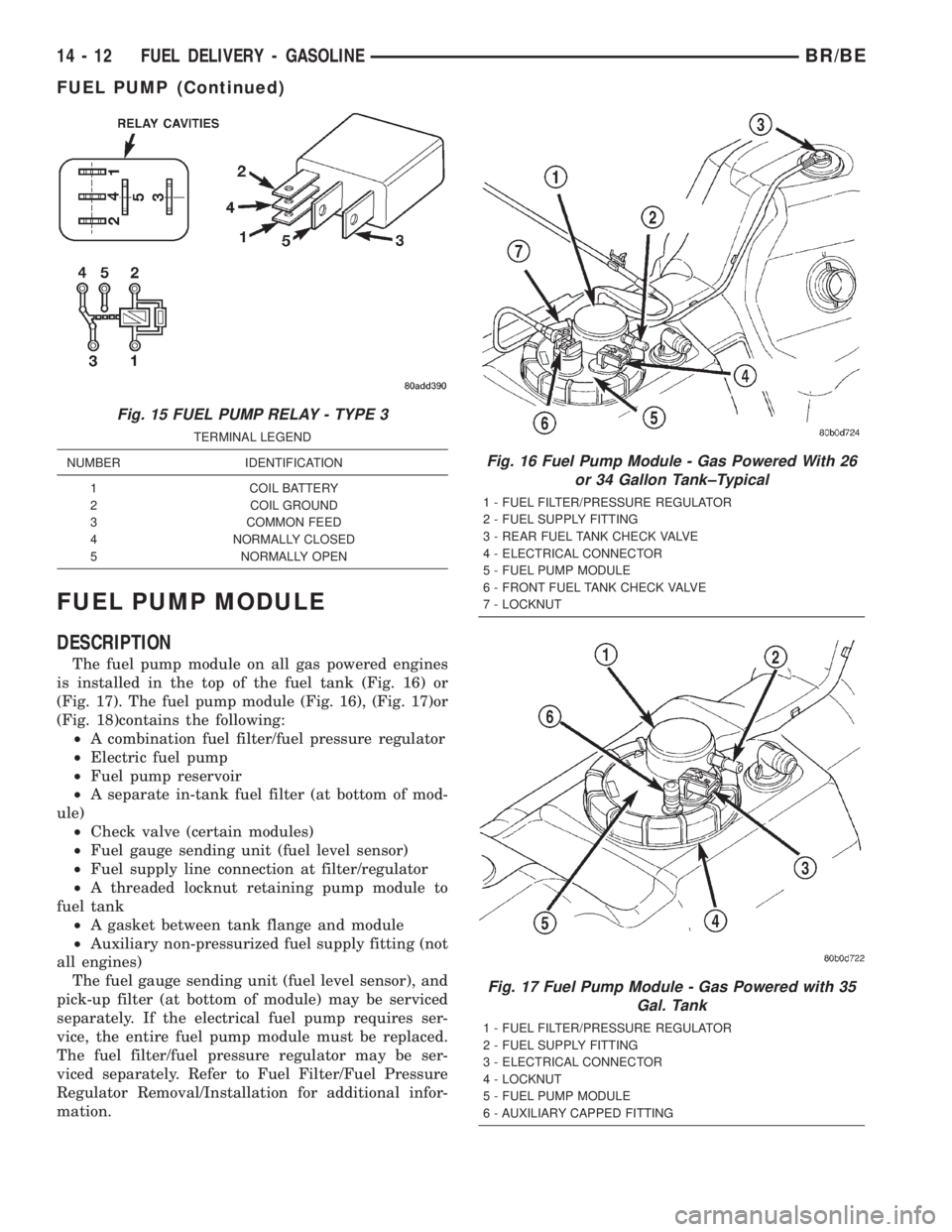
The fuel pump module on all gas powered engines
is installed in the top of the fuel tank (Fig. 16) or
(Fig. 17). The fuel pump module (Fig. 16), (Fig. 17)or
(Fig. 18)contains the following:
²A combination fuel filter/fuel pressure regulator
²Electric fuel pump
²Fuel pump reservoir
²A separate in-tank fuel filter (at bottom of mod-
ule)
²Check valve (certain modules)
²Fuel gauge sending unit (fuel level sensor)
²Fuel supply line connection at filter/regulator
²A threaded locknut retaining pump module to
fuel tank
²A gasket between tank flange and module
²Auxiliary non-pressurized fuel supply fitting (not
all engines)
The fuel gauge sending unit (fuel level sensor), and
pick-up filter (at bottom of module) may be serviced
separately. If the electrical fuel pump requires ser-
vice, the entire fuel pump module must be replaced.
The fuel filter/fuel pressure regulator may be ser-
viced separately. Refer to Fuel Filter/Fuel Pressure
Regulator Removal/Installation for additional infor-
mation.
Fig. 15 FUEL PUMP RELAY - TYPE 3
TERMINAL LEGEND
NUMBER IDENTIFICATION
1 COIL BATTERY
2 COIL GROUND
3 COMMON FEED
4 NORMALLY CLOSED
5 NORMALLY OPEN
Fig. 16 Fuel Pump Module - Gas Powered With 26
or 34 Gallon Tank±Typical
1 - FUEL FILTER/PRESSURE REGULATOR
2 - FUEL SUPPLY FITTING
3 - REAR FUEL TANK CHECK VALVE
4 - ELECTRICAL CONNECTOR
5 - FUEL PUMP MODULE
6 - FRONT FUEL TANK CHECK VALVE
7 - LOCKNUT
Fig. 17 Fuel Pump Module - Gas Powered with 35
Gal. Tank
1 - FUEL FILTER/PRESSURE REGULATOR
2 - FUEL SUPPLY FITTING
3 - ELECTRICAL CONNECTOR
4 - LOCKNUT
5 - FUEL PUMP MODULE
6 - AUXILIARY CAPPED FITTING
14 - 12 FUEL DELIVERY - GASOLINEBR/BE
FUEL PUMP (Continued)
Page 1312 of 2255
OPERATION
Refer to Fuel Pump, Fuel Filter/Fuel Pressure Reg-
ulator and Fuel Gauge Sending Unit.
REMOVAL
WARNING: THE FUEL SYSTEM IS UNDER A CON-
STANT PRESSURE (EVEN WITH THE ENGINE OFF).
BEFORE SERVICING THE FUEL PUMP MODULE,
THE FUEL SYSTEM PRESSURE MUST BE
RELEASED.
(1) Drain and remove fuel tank. Refer to Fuel
Tank - All Engines in the Removal/Installation sec-
tion.
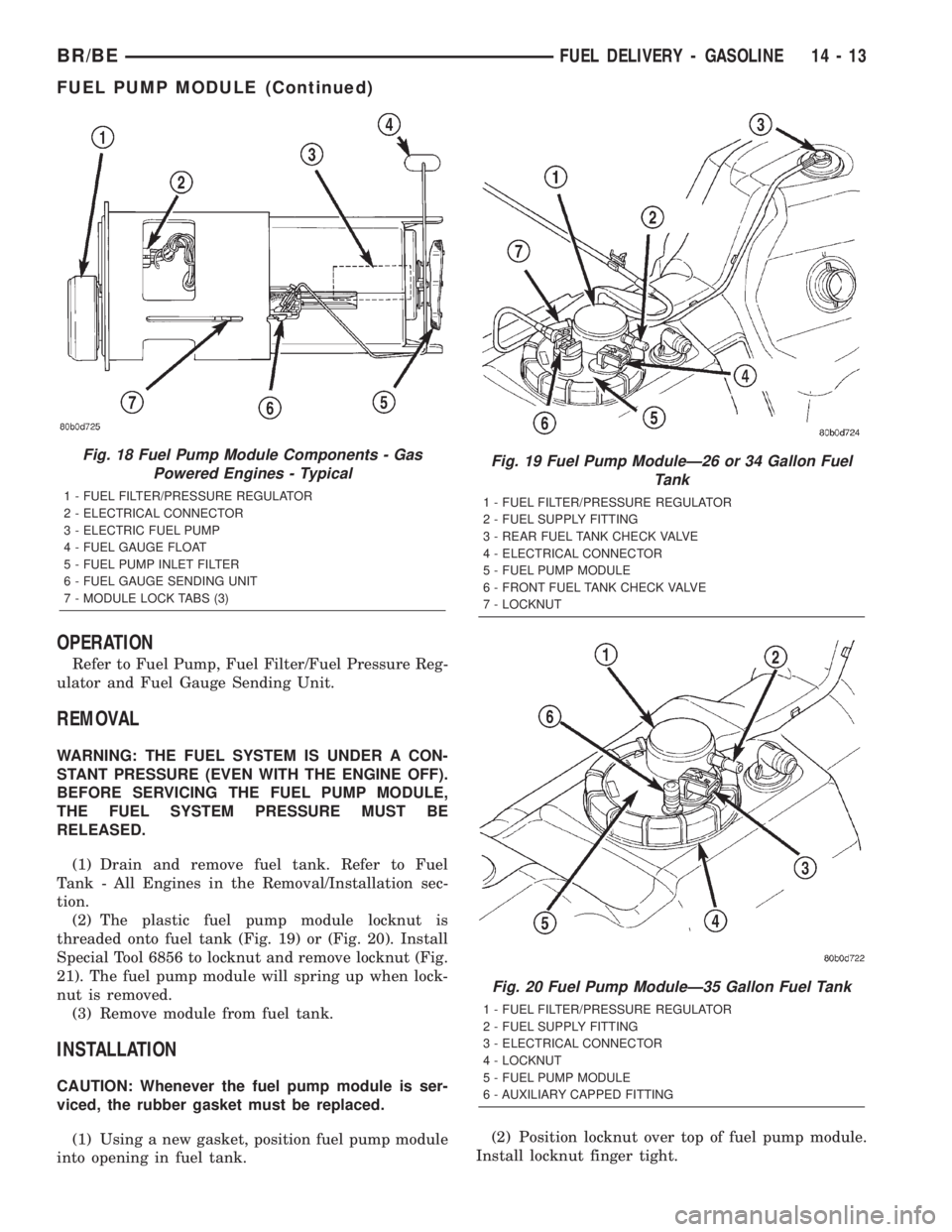
(2) The plastic fuel pump module locknut is
threaded onto fuel tank (Fig. 19) or (Fig. 20). Install
Special Tool 6856 to locknut and remove locknut (Fig.
21). The fuel pump module will spring up when lock-
nut is removed.
(3) Remove module from fuel tank.
INSTALLATION
CAUTION: Whenever the fuel pump module is ser-
viced, the rubber gasket must be replaced.
(1) Using a new gasket, position fuel pump module
into opening in fuel tank.(2) Position locknut over top of fuel pump module.
Install locknut finger tight.
Fig. 18 Fuel Pump Module Components - Gas
Powered Engines - Typical
1 - FUEL FILTER/PRESSURE REGULATOR
2 - ELECTRICAL CONNECTOR
3 - ELECTRIC FUEL PUMP
4 - FUEL GAUGE FLOAT
5 - FUEL PUMP INLET FILTER
6 - FUEL GAUGE SENDING UNIT
7 - MODULE LOCK TABS (3)
Fig. 19 Fuel Pump ModuleÐ26 or 34 Gallon Fuel
Tank
1 - FUEL FILTER/PRESSURE REGULATOR
2 - FUEL SUPPLY FITTING
3 - REAR FUEL TANK CHECK VALVE
4 - ELECTRICAL CONNECTOR
5 - FUEL PUMP MODULE
6 - FRONT FUEL TANK CHECK VALVE
7 - LOCKNUT
Fig. 20 Fuel Pump ModuleÐ35 Gallon Fuel Tank
1 - FUEL FILTER/PRESSURE REGULATOR
2 - FUEL SUPPLY FITTING
3 - ELECTRICAL CONNECTOR
4 - LOCKNUT
5 - FUEL PUMP MODULE
6 - AUXILIARY CAPPED FITTING
BR/BEFUEL DELIVERY - GASOLINE 14 - 13
FUEL PUMP MODULE (Continued)