2002 DODGE RAM lock
[x] Cancel search: lockPage 1381 of 2255
CAUTION: Be sure that the high-pressure fuel lines
are installed in the same order that they were
removed.
(1) Lubricate threads of injector line fittings with
clean engine oil.
(2) Loosen, but do not remove, all fuel line support
bracket bolts.
(3) Installrearinjection line bundle beginning
with cylinder head (fuel injector) connections, fol-
lowed by injection pump connections. Tighten all fit-
tings finger tight.
(4) Tighten fittings at fuel injector ends for cylin-
ders number 6 and 5 to 38 N´m (28 ft. lbs.) torque.
Do not tighten number 3 line at this time. It
will be tightened during bleeding procedure.
(5) Tighten 3 fittings at fuel injection pump ends
to 24 N´m (18 ft. lbs.) torque.
(6) Installfrontinjection line bundle beginning
with cylinder head (fuel injector) connections, fol-
lowed by injection pump connections. Tighten all fit-
tings finger tight.
(7) Tighten fitting at fuel injector end for cylinder
number 2 to 38 N´m (28 ft. lbs.) torque.Do not
tighten lines number 1 or 4 at this time. They
will be tightened during bleeding procedure.
(8) Tighten remaining 3 fittings at fuel injection
pump ends to 24 N´m (18 ft. lbs.) torque.
(9) Install fuel line support bracket bolts to intake
manifold and tighten to 24 N´m (18 ft. lbs.) torque.
CAUTION: Be sure fuel lines are not contacting
each other or any other component. Noise will
result.
(10) Install engine lifting bracket at rear of intake
manifold. Tighten 2 bolts to 77 N´m (57 ft. lbs.)
torque.
(11) Install cable bracket housing/cable assembly
and tighten 3 mounting bolts to 24 N´m (18 ft. lbs.)
torque.
(12) Clean any old gasket material below and
above intake manifold air heater element block. Also
clean mating areas at intake manifold and air intake
housing.
(13) Using new gaskets, position intake manifold
air heater element block to engine.
(14) Install air intake housing and position ground
cable. Install 4 mounting bolts and tighten to 24 N´m
(18 ft. lbs.) torque.
(15) Install air tube (intake manifold-to-charge air
cooler) (Fig. 49). Tighten clamps to 8 N´m (72 in. lbs.)
torque.
(16) Install engine oil dipstick tube support mount-
ing bolt and tighten to 24 N´m (18 ft. lbs.) torque.
(17) Install engine oil dipstick to engine.(18) Connect 2 electrical cables to cable mounting
studs.
(19) Connect electrical connector to bottom of
APPS by pushing connector upward until it snaps
into position.
(20) Connect wiring harness (clip) at bottom of
Accelerator Pedal Position Sensor (APPS) mounting
bracket (Fig. 48).
(21) Connect front wiring clip (Fig. 49) to cable
bracket housing.
(22) Install cable cover (Fig. 47).
(23) Connect both negative battery cables to both
batteries.
(24) Bleed air from fuel system. Do this at fuel
injector ends of lines. Use cylinders numbers 1, 3 and
4 for bleeding. (Refer to 14 - FUEL SYSTEM/FUEL
DELIVERY - STANDARD PROCEDURE). After
bleeding, tighten fittings to 38 N´m (28 ft. lbs.)
torque.
(25) Check lines/fittings for leaks.
FUEL TANK
DESCRIPTION - DIESEL FUEL TANK
The fuel tank is similar to the tank used with gas-
oline powered models. The tank is equipped with a
separate fuel return line and a different fuel tank
module for diesel powered models. A fuel tank
mounted, electric fuel pump is not used with diesel
powered models. Refer to Fuel Tank Module for addi-
tional information.
For removal and installation procedures, refer to
Fuel Tank - Gasoline Engines.
FUEL TANK MODULE
DESCRIPTION
An electric fuel pump isnot usedin the fuel tank
module for diesel powered engines. Fuel is supplied
by the engine mounted fuel transfer pump and the
fuel injection pump.
The fuel tank module is installed in the top of the
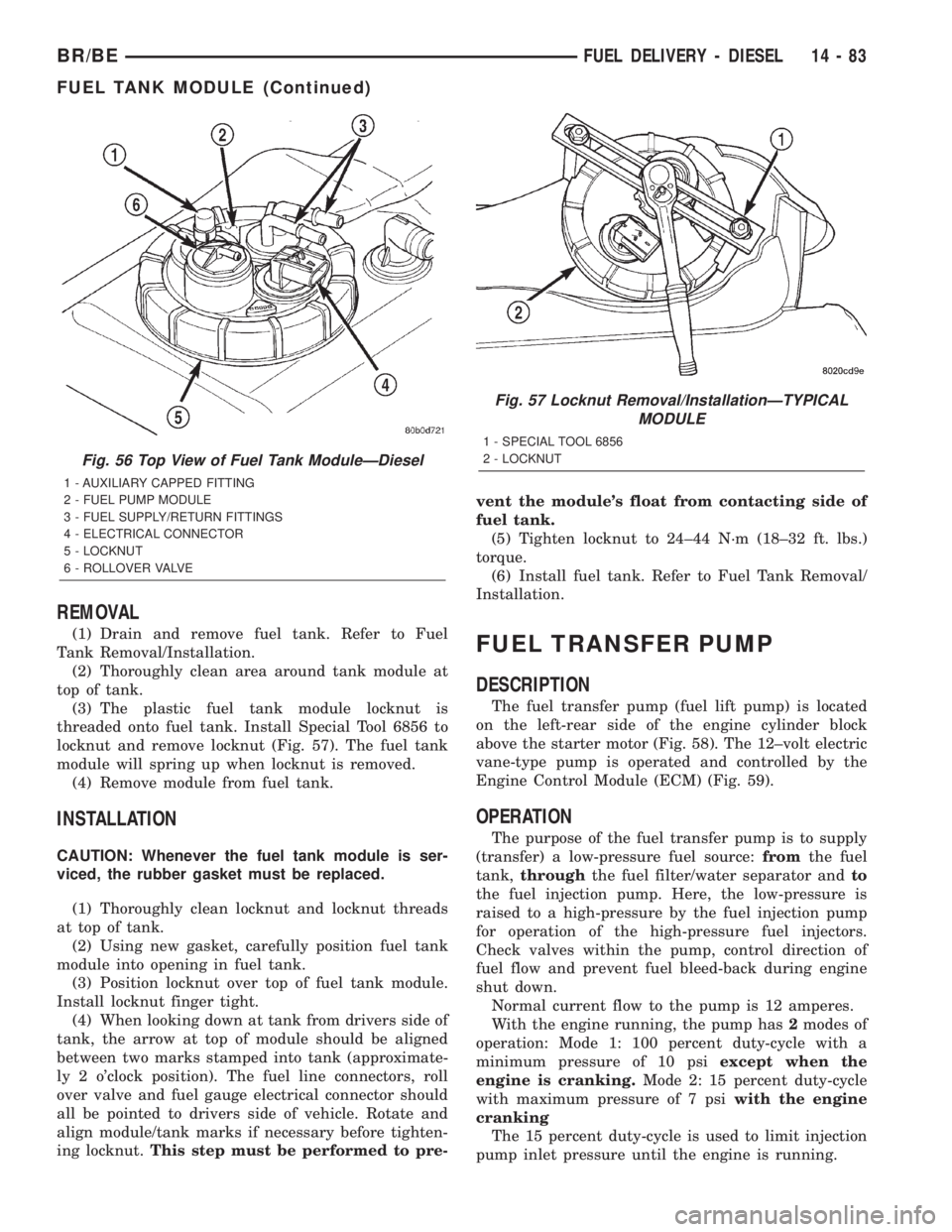
fuel tank (Fig. 56). The fuel tank module (Fig. 56)
contains the following components:
²Fuel reservoir
²A separate in-tank fuel filter
²Rollover valve
²Fuel gauge sending unit (fuel level sensor)
²Fuel supply line connection
²Fuel return line connection
²Auxiliary non-pressurized fuel supply fitting
OPERATION
Refer to Fuel Gauge Sending Unit.
14 - 82 FUEL DELIVERY - DIESELBR/BE
FUEL LINES (Continued)
Page 1382 of 2255
REMOVAL
(1) Drain and remove fuel tank. Refer to Fuel
Tank Removal/Installation.
(2) Thoroughly clean area around tank module at
top of tank.
(3) The plastic fuel tank module locknut is
threaded onto fuel tank. Install Special Tool 6856 to
locknut and remove locknut (Fig. 57). The fuel tank
module will spring up when locknut is removed.
(4) Remove module from fuel tank.
INSTALLATION
CAUTION: Whenever the fuel tank module is ser-
viced, the rubber gasket must be replaced.
(1) Thoroughly clean locknut and locknut threads
at top of tank.
(2) Using new gasket, carefully position fuel tank
module into opening in fuel tank.
(3) Position locknut over top of fuel tank module.
Install locknut finger tight.
(4) When looking down at tank from drivers side of
tank, the arrow at top of module should be aligned
between two marks stamped into tank (approximate-
ly 2 o'clock position). The fuel line connectors, roll
over valve and fuel gauge electrical connector should
all be pointed to drivers side of vehicle. Rotate and
align module/tank marks if necessary before tighten-
ing locknut.This step must be performed to pre-vent the module's float from contacting side of
fuel tank.
(5) Tighten locknut to 24±44 N´m (18±32 ft. lbs.)
torque.
(6) Install fuel tank. Refer to Fuel Tank Removal/
Installation.
FUEL TRANSFER PUMP
DESCRIPTION
The fuel transfer pump (fuel lift pump) is located
on the left-rear side of the engine cylinder block
above the starter motor (Fig. 58). The 12±volt electric
vane-type pump is operated and controlled by the
Engine Control Module (ECM) (Fig. 59).
OPERATION
The purpose of the fuel transfer pump is to supply
(transfer) a low-pressure fuel source:fromthe fuel
tank,throughthe fuel filter/water separator andto
the fuel injection pump. Here, the low-pressure is
raised to a high-pressure by the fuel injection pump
for operation of the high-pressure fuel injectors.
Check valves within the pump, control direction of
fuel flow and prevent fuel bleed-back during engine
shut down.
Normal current flow to the pump is 12 amperes.
With the engine running, the pump has2modes of
operation: Mode 1: 100 percent duty-cycle with a
minimum pressure of 10 psiexcept when the
engine is cranking.Mode 2: 15 percent duty-cycle
with maximum pressure of 7 psiwith the engine
cranking
The 15 percent duty-cycle is used to limit injection
pump inlet pressure until the engine is running.
Fig. 56 Top View of Fuel Tank ModuleÐDiesel
1 - AUXILIARY CAPPED FITTING
2 - FUEL PUMP MODULE
3 - FUEL SUPPLY/RETURN FITTINGS
4 - ELECTRICAL CONNECTOR
5 - LOCKNUT
6 - ROLLOVER VALVE
Fig. 57 Locknut Removal/InstallationÐTYPICAL
MODULE
1 - SPECIAL TOOL 6856
2 - LOCKNUT
BR/BEFUEL DELIVERY - DIESEL 14 - 83
FUEL TANK MODULE (Continued)
Page 1385 of 2255
(7) Because fuel pump relay was removed, a Diag-
nostic Trouble Code (DTC) may have been set. After
testing is completed, and relay has been installed,
use DRB scan tool to remove DTC.
Fuel Supply Restriction Test:
Due to very small vacuum specifications, the DRB
scan tool along with the Periphal Expansion Port
(PEP) Module and 0±15 psi transducer must be used.
(8) Verify transfer pump pressure is OK before
performing restriction test.
(9) Locate and disconnect fuel supply line quick-
connect fitting at left-rear of engine (Fig. 63). After
disconnecting line, plastic clip will remain attached
to metal fuel line at engine. Carefully remove clip
from metal line. Snap same clip into fuel supply
hose.
(10) Install Special Rubber Adapter Hose Tool
6631 (3/8º) into ends of disconnected fuel supply line.
(11) Install transducer from PEP module to brass
ªTº fitting on tool 6631.
(12) Hook up DRB scan tool to transducer.
WARNING: DO NOT STAND IN LINE WITH THE
COOLING FAN FOR THE FOLLOWING STEPS.
(13) Start engine and record vacuum reading with
engine speed at high-idle (high-idle means engine
speed is at 100 percent throttle and no load). The
fuel restriction testMUSTbe done with engine speed
at high-idle.
(14) If vacuum reading islessthan 6 in/hg. (0±152
mm hg.), test is OK. If vacuum reading ishigher
than 6 in/hg. (152 mm hg.), restriction exists in fuel
supply line or in fuel tank module. Check fuel supply
line for damage, dents or kinking. If OK, remove
module and check module and lines for blockage.
Also check fuel pump inlet filter at bottom of module
for obstructions.
Testing For Air Leaks in Fuel Supply Side:
(15) A 3±foot section of 3/8º I.D. clear tubing is
required for this test.
(16) Using a tire core valve removal tool, carefully
remove core valve from inlet fitting test port.
(17) Attach and clamp the 3/8ºclear hose to fitting
nipple.
(18) Place other end of hose into a large clear con-
tainer. Allow hose to loop as high as possibleabove
test port.
(19) The fuel transfer pump can be put into a 25
second run (test) mode if key is quickly turned to
crank position and released back to run position
without starting engine.
To prevent engine from starting in this test, first
remove fuel system relay (fuel injection pump relay).
Relay is located in Power Distribution Center (PDC).
Refer to label under PDC cover for relay location.
Because fuel pump relay was removed, a DiagnosticTrouble Code (DTC) may have been set. After testing
is completed, and relay has been installed, use DRB
scan tool to remove DTC.
(20) Allow air to purge from empty hose before
examining for air bubbles. Air bubbles should not be
present.
(21) If bubbles are present, check for leaks in sup-
ply line to fuel tank.
(22) If supply line is not leaking, remove fuel tank
module and remove filter at bottom of module (filter
snaps to module). Check for leaks between supply
nipple at top of module, and filter opening at bottom
of module. Replace module if necessary.
(23) After performing test, install core back into
test fitting. Before installing protective cap, be sure
fitting is not leaking.
REMOVAL
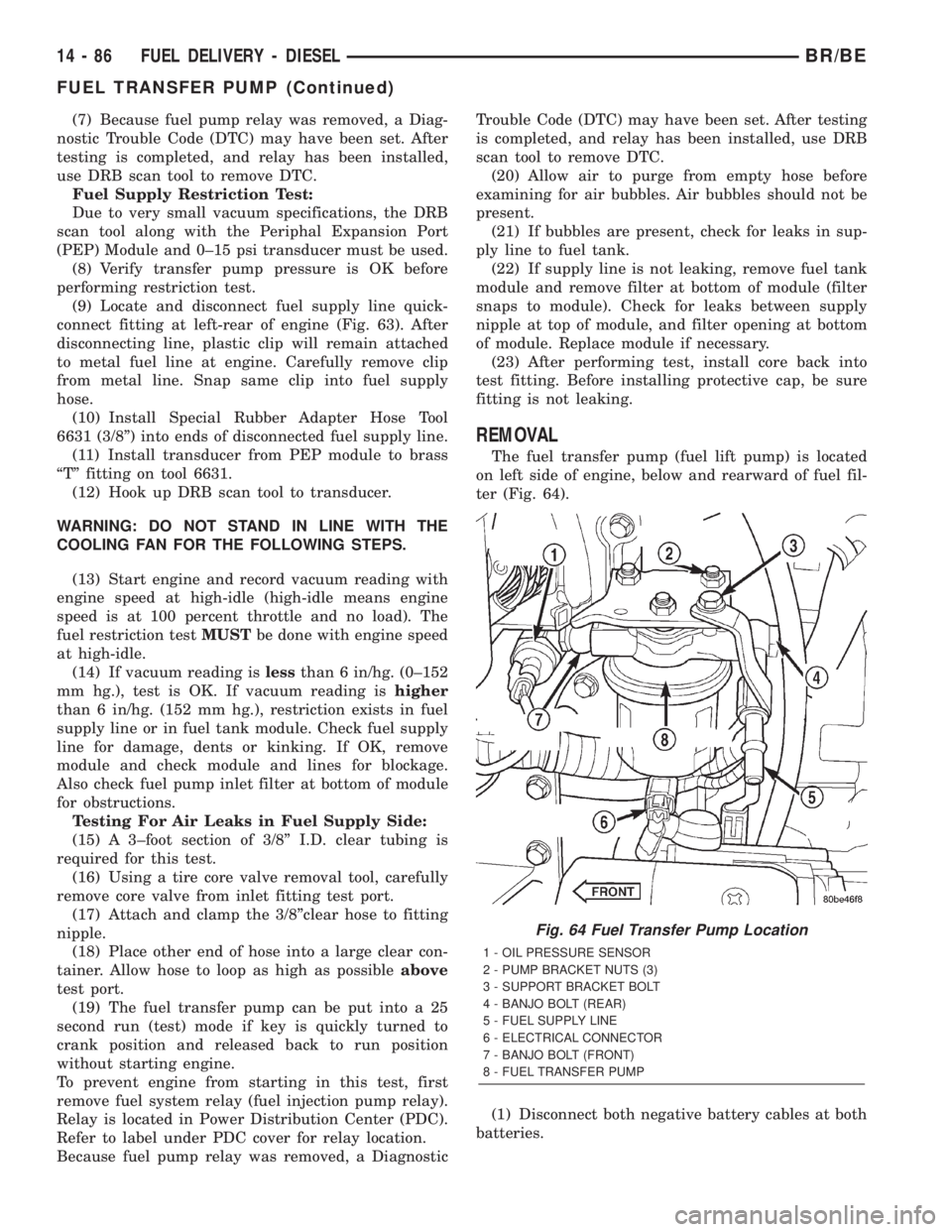
The fuel transfer pump (fuel lift pump) is located
on left side of engine, below and rearward of fuel fil-
ter (Fig. 64).
(1) Disconnect both negative battery cables at both
batteries.
Fig. 64 Fuel Transfer Pump Location
1 - OIL PRESSURE SENSOR
2 - PUMP BRACKET NUTS (3)
3 - SUPPORT BRACKET BOLT
4 - BANJO BOLT (REAR)
5 - FUEL SUPPLY LINE
6 - ELECTRICAL CONNECTOR
7 - BANJO BOLT (FRONT)
8 - FUEL TRANSFER PUMP
14 - 86 FUEL DELIVERY - DIESELBR/BE
FUEL TRANSFER PUMP (Continued)
Page 1393 of 2255
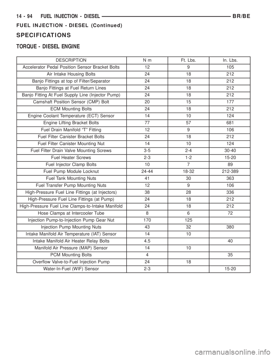
SPECIFICATIONS
TORQUE - DIESEL ENGINE
DESCRIPTION N m Ft. Lbs. In. Lbs.
Accelerator Pedal Position Sensor Bracket Bolts 12 9 105
Air Intake Housing Bolts 24 18 212
Banjo Fittings at top of Filter/Separator 24 18 212
Banjo Fittings at Fuel Return Lines 24 18 212
Banjo Fitting At Fuel Supply Line (Injector Pump) 24 18 212
Camshaft Position Sensor (CMP) Bolt 20 15 177
ECM Mounting Bolts 24 18 212
Engine Coolant Temperature (ECT) Sensor 14 10 124
Engine Lifting Bracket Bolts 77 57 681
Fuel Drain Manifold ªTº Fitting 12 9 106
Fuel Filter Canister Bracket Bolts 24 18 212
Fuel Filter Canister Mounting Nut 14 10 124
Fuel Filter Drain Valve Mounting Screws 3-5 2-4 30-40
Fuel Heater Screws 2-3 1-2 15-20
Fuel Injector Clamp Bolts 10 7 89
Fuel Pump Module Locknut 24-44 18-32 212-389
Fuel Tank Mounting Nuts 41 30 363
Fuel Transfer Pump Mounting Nuts 12 9 106
High-Pressure Fuel Line Fittings (at Injectors) 38 28 336
High-Pressure Fuel Line Fittings (at Pump) 24 18 212
High-Pressure Fuel Line Clamps-to-Intake Manifold 24 18 212
Hose Clamps at Intercooler Tube 8 6 72
Injection Pump-to-Injection Pump Gear Nut 170 125
Injection Pump Mounting Nuts 43 32 380
Intake Manifold Air Temperature (IAT) Sensor 14 10
Intake Manifold Air Heater Relay Bolts 4.5 40
Manifold Air Pressure (MAP) Sensor 14 10
PCM Mounting Bolts 4 35
Overflow Valve-to-Fuel Injection Pump 24 18
Water-In-Fuel (WIF) Sensor 2-3 15-20
14 - 94 FUEL INJECTION - DIESELBR/BE
FUEL INJECTION - DIESEL (Continued)
Page 1403 of 2255
FUEL TEMPERATURE SENSOR
DESCRIPTION
Two different fuel temperature sensors are used.
One of the sensors is located inside of the Bosch
VP44 fuel injection pump and is a non-serviceable
part. The other fuel temperature sensor is located in
the top of the fuel filter housing and is serviceable
(serviceable if replacing the fuel heater).
OPERATION
The sensor located in the Bosch VP44 fuel injection
pump is used to check fuel temperature within the
injection pump and to set a Diagnostic Trouble Code
(DTC) if a specific high fuel temperature has been
reached. If high temperature has been reached,
engine power will be de-rated by the Engine Control
Module (ECM).
The sensor located in the top of the fuel filter hous-
ing is used to control the fuel heater element. Refer
to Fuel Heater Description and Operation for addi-
tional information.
INTAKE AIR HEATER
DESCRIPTION
The intake manifold air heater element assembly
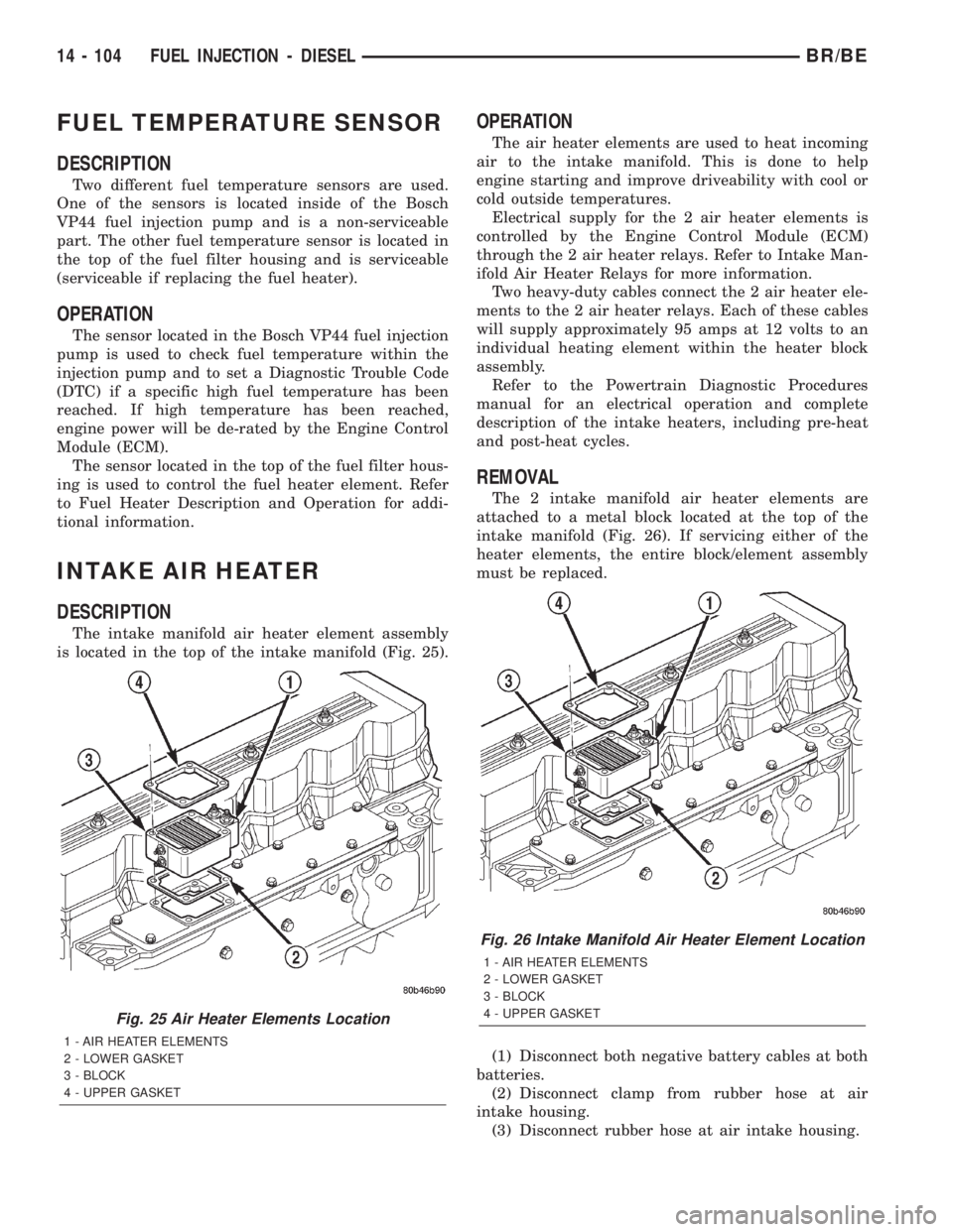
is located in the top of the intake manifold (Fig. 25).
OPERATION
The air heater elements are used to heat incoming
air to the intake manifold. This is done to help
engine starting and improve driveability with cool or
cold outside temperatures.
Electrical supply for the 2 air heater elements is
controlled by the Engine Control Module (ECM)
through the 2 air heater relays. Refer to Intake Man-
ifold Air Heater Relays for more information.
Two heavy-duty cables connect the 2 air heater ele-
ments to the 2 air heater relays. Each of these cables
will supply approximately 95 amps at 12 volts to an
individual heating element within the heater block
assembly.
Refer to the Powertrain Diagnostic Procedures
manual for an electrical operation and complete
description of the intake heaters, including pre-heat
and post-heat cycles.
REMOVAL
The 2 intake manifold air heater elements are
attached to a metal block located at the top of the
intake manifold (Fig. 26). If servicing either of the
heater elements, the entire block/element assembly
must be replaced.
(1) Disconnect both negative battery cables at both
batteries.
(2) Disconnect clamp from rubber hose at air
intake housing.
(3) Disconnect rubber hose at air intake housing.
Fig. 25 Air Heater Elements Location
1 - AIR HEATER ELEMENTS
2 - LOWER GASKET
3 - BLOCK
4 - UPPER GASKET
Fig. 26 Intake Manifold Air Heater Element Location
1 - AIR HEATER ELEMENTS
2 - LOWER GASKET
3 - BLOCK
4 - UPPER GASKET
14 - 104 FUEL INJECTION - DIESELBR/BE
Page 1404 of 2255
(4) Remove engine oil dipstick tube mounting bolt
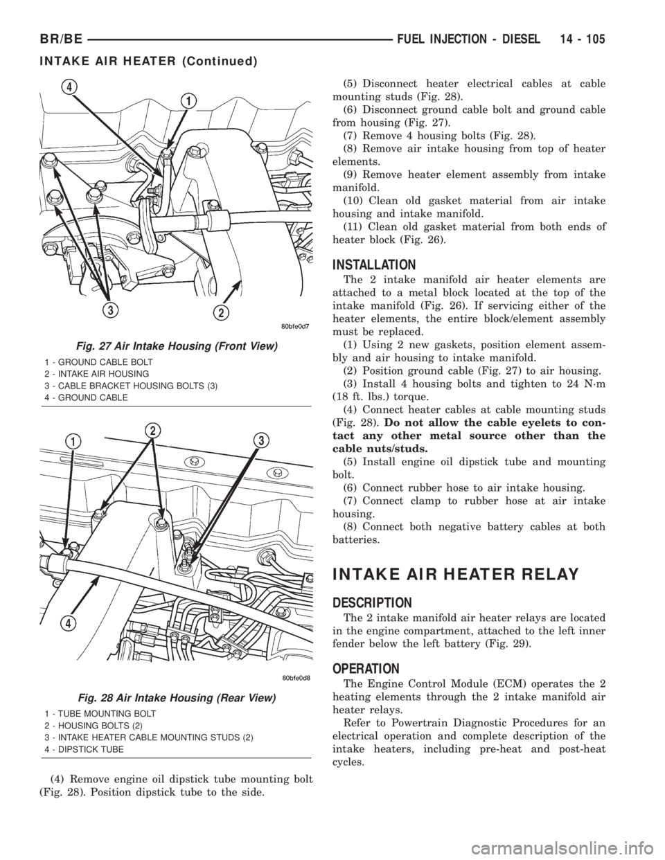
(Fig. 28). Position dipstick tube to the side.(5) Disconnect heater electrical cables at cable
mounting studs (Fig. 28).
(6) Disconnect ground cable bolt and ground cable
from housing (Fig. 27).
(7) Remove 4 housing bolts (Fig. 28).
(8) Remove air intake housing from top of heater
elements.
(9) Remove heater element assembly from intake
manifold.
(10) Clean old gasket material from air intake
housing and intake manifold.
(11) Clean old gasket material from both ends of
heater block (Fig. 26).
INSTALLATION
The 2 intake manifold air heater elements are
attached to a metal block located at the top of the
intake manifold (Fig. 26). If servicing either of the
heater elements, the entire block/element assembly
must be replaced.
(1) Using 2 new gaskets, position element assem-
bly and air housing to intake manifold.
(2) Position ground cable (Fig. 27) to air housing.
(3) Install 4 housing bolts and tighten to 24 N´m
(18 ft. lbs.) torque.
(4) Connect heater cables at cable mounting studs
(Fig. 28).Do not allow the cable eyelets to con-
tact any other metal source other than the
cable nuts/studs.
(5) Install engine oil dipstick tube and mounting
bolt.
(6) Connect rubber hose to air intake housing.
(7) Connect clamp to rubber hose at air intake
housing.
(8) Connect both negative battery cables at both
batteries.
INTAKE AIR HEATER RELAY
DESCRIPTION
The 2 intake manifold air heater relays are located
in the engine compartment, attached to the left inner
fender below the left battery (Fig. 29).
OPERATION
The Engine Control Module (ECM) operates the 2
heating elements through the 2 intake manifold air
heater relays.
Refer to Powertrain Diagnostic Procedures for an
electrical operation and complete description of the
intake heaters, including pre-heat and post-heat
cycles.
Fig. 27 Air Intake Housing (Front View)
1 - GROUND CABLE BOLT
2 - INTAKE AIR HOUSING
3 - CABLE BRACKET HOUSING BOLTS (3)
4 - GROUND CABLE
Fig. 28 Air Intake Housing (Rear View)
1 - TUBE MOUNTING BOLT
2 - HOUSING BOLTS (2)
3 - INTAKE HEATER CABLE MOUNTING STUDS (2)
4 - DIPSTICK TUBE
BR/BEFUEL INJECTION - DIESEL 14 - 105
INTAKE AIR HEATER (Continued)
Page 1409 of 2255
INSTALLATION
(1) Install cable through mounting hole on cable
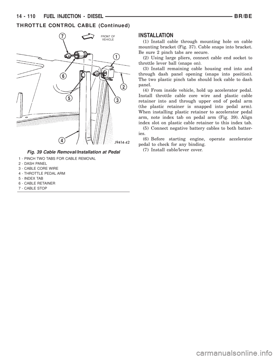
mounting bracket (Fig. 37). Cable snaps into bracket.
Be sure 2 pinch tabs are secure.
(2) Using large pliers, connect cable end socket to
throttle lever ball (snaps on).
(3) Install remaining cable housing end into and
through dash panel opening (snaps into position).
The two plastic pinch tabs should lock cable to dash
panel.
(4) From inside vehicle, hold up accelerator pedal.
Install throttle cable core wire and plastic cable
retainer into and through upper end of pedal arm
(the plastic retainer is snapped into pedal arm).
When installing plastic retainer to accelerator pedal
arm, note index tab on pedal arm (Fig. 39). Align
index slot on plastic cable retainer to this index tab.
(5) Connect negative battery cables to both batter-
ies.
(6) Before starting engine, operate accelerator
pedal to check for any binding.
(7) Install cable/lever cover.
Fig. 39 Cable Removal/Installation at Pedal
1 - PINCH TWO TABS FOR CABLE REMOVAL
2 - DASH PANEL
3 - CABLE CORE WIRE
4 - THROTTLE PEDAL ARM
5 - INDEX TAB
6 - CABLE RETAINER
7 - CABLE STOP
14 - 110 FUEL INJECTION - DIESELBR/BE
THROTTLE CONTROL CABLE (Continued)
Page 1415 of 2255
COLUMN
TABLE OF CONTENTS
page page
COLUMN
DESCRIPTION..........................6
OPERATION
SERVICE PRECAUTIONS................6
REMOVAL.............................6
INSTALLATION..........................8
SPECIFICATIONS
TORQUE CHART......................9
KEY-IN IGNITION SWITCH
DESCRIPTION..........................9
DIAGNOSIS AND TESTING - IGNITION
SWITCH AND KEY LOCK CYLINDER.......9
LOCK CYLINDER
REMOVAL.............................10INSTALLATION.........................10
IGNITION SWITCH
DESCRIPTION.........................11
OPERATION...........................11
DIAGNOSIS AND TESTING - IGNITION
SWITCH.............................11
REMOVAL.............................12
INSTALLATION.........................12
GEAR SHIFT LEVER
REMOVAL.............................14
INSTALLATION.........................15
STEERING WHEEL
REMOVAL.............................15
INSTALLATION.........................15
COLUMN
DESCRIPTION
The tilt and standard column (Fig. 1) has been
designed to be serviced as an assembly; less wiring,
switches, shrouds, steering wheel, etc. Most steering
column components can be serviced without remov-
ing the steering column from the vehicle.
OPERATION
SERVICE PRECAUTIONS
Safety goggles should be worn at all times when
working on steering columns.
To service the steering wheel, switches or the air-
bag, refer to the WARNINGS and CAUTIONS below.
WARNING: THE AIRBAG SYSTEM IS A SENSITIVE,
COMPLEX ELECTRO-MECHANICAL UNIT. BEFORE
ATTEMPTING TO DIAGNOSE, REMOVE OR INSTALL
THE AIRBAG SYSTEM COMPONENTS YOU MUST
FIRST DISCONNECT AND ISOLATE THE BATTERY
NEGATIVE (GROUND) CABLE. THEN WAIT TWO
MINUTES FOR THE SYSTEM CAPACITOR TO DIS-
CHARGE. FAILURE TO DO SO COULD RESULT IN
ACCIDENTAL DEPLOYMENT OF THE AIRBAG AND
POSSIBLE PERSONAL INJURY. THE FASTENERS,
SCREWS, AND BOLTS, ORIGINALLY USED FOR
THE AIRBAG COMPONENTS, HAVE SPECIAL COAT-INGS AND ARE SPECIFICALLY DESIGNED FOR THE
AIRBAG SYSTEM. THEY MUST NEVER BE
REPLACED WITH ANY SUBSTITUTES. ANYTIME A
NEW FASTENER IS NEEDED, REPLACE WITH THE
CORRECT FASTENERS PROVIDED IN THE SERVICE
PACKAGE OR FASTENERS LISTED IN THE PARTS
BOOKS.
CAUTION: Do not hammer on steering column shaft
or shift tube. This may cause the shaft/shift tube to
collapse or damage the bearing.
CAUTION: Do not attempt to remove the pivot pins
to disassemble the tilting mechanism. Do not
remove shaft lock plate, plate retainer, park lock
link or slider. This will damage the column (Fig. 2)
and (Fig. 3).
REMOVAL
(1) Position the front wheels straight ahead.
(2) Disconnect the negative (ground) cable from
the battery.
(3) Remove the airbag, (Refer to 8 - ELECTRICAL/
RESTRAINTS/DRIVER AIRBAG - REMOVAL).
(4) Remove the steering wheel with an appropriate
puller,(Refer to 19 - STEERING/COLUMN/STEER-
ING WHEEL - REMOVAL).
19 - 6 COLUMNBR/BE