2002 DODGE RAM torque
[x] Cancel search: torquePage 2 of 2255

INTRODUCTION
TABLE OF CONTENTS
page page
VEHICLE SAFETY CERTIFICATION LABEL
DESCRIPTION..........................1
VEHICLE IDENTIFICATION NUMBER
DESCRIPTION..........................1
VEHICLE EMISSION CONTROL INFORMATION
(VECI)
DESCRIPTION..........................3
EQUIPMENT IDENTIFICATION PLATE
DESCRIPTION..........................3
BODY CODE PLATE
DESCRIPTION..........................4
INTERNATIONAL VEHICLE CONTROL &
DISPLAY SYMBOLS
DESCRIPTION - INTERNATIONAL SYMBOLS . . . 5FASTENER IDENTIFICATION
DESCRIPTION..........................6
FASTENER USAGE
DESCRIPTION..........................9
THREADED HOLE REPAIR
DESCRIPTION..........................9
METRIC SYSTEM
DESCRIPTION..........................9
TORQUE REFERENCES
DESCRIPTION.........................11
VEHICLE SAFETY
CERTIFICATION LABEL
DESCRIPTION
A vehicle safety certification label (Fig. 1) is
attached to every Chrysler Corporation vehicle. The
label certifies that the vehicle conforms to all appli-
cable Federal Motor Vehicle Safety Standards. The
label also lists:
²Month and year of vehicle manufacture.
²Gross Vehicle Weight Rating (GVWR). The gross
front and rear axle weight ratings (GAWR's) are
based on a minimum rim size and maximum cold tire
inflation pressure.
²Vehicle Identification Number (VIN).
²Type of vehicle.
²Type of rear wheels.
²Bar code.
²Month, Day and Hour (MDH) of final assembly.
²Paint and Trim codes.
²Country of origin.
The label is located on the driver-side door shut-
face.
VEHICLE IDENTIFICATION
NUMBER
DESCRIPTION
VIN CODING/LOCATIONS
The Vehicle Identification Number (VIN) plate is
located on the lower windshield fence near the left
A-pillar (Fig. 2). The VIN contains 17 characters that
provide data concerning the vehicle. Refer to the VIN
decoding chart to determine the identification of a
vehicle.
The Vehicle Identification Number is also
imprinted on the:
²Body Code Plate.
²Equipment Identification Plate.
²Vehicle Safety Certification Label.
²Frame rail.
Fig. 1 Vehicle Safety Certification Label
BR/BEINTRODUCTION 1
Page 10 of 2255

FASTENER USAGE
DESCRIPTION
WARNING: USE OF AN INCORRECT FASTENER
MAY RESULT IN COMPONENT DAMAGE OR PER-
SONAL INJURY.
Figure art, specifications and torque references in
this Service Manual are identified in metric and SAE
format.
During any maintenance or repair procedures, it is
important to salvage all fasteners (nuts, bolts, etc.)
for reassembly. If the fastener is not salvageable, a
fastener of equivalent specification must be used.
THREADED HOLE REPAIR
DESCRIPTION
Most stripped threaded holes can be repaired using
a Helicoilt. Follow the vehicle or Helicoiltrecommen-
dations for application and repair procedures.
METRIC SYSTEM
DESCRIPTION
The metric system is based on quantities of one,
ten, one hundred, one thousand and one million.
The following chart will assist in converting metric
units to equivalent English and SAE units, or vise
versa.
CONVERSION FORMULAS AND EQUIVALENT VALUES
MULTIPLY BY TO GET MULTIPLY BY TO GET
in-lbs x 0.11298 = Newton Meters
(N´m)N´m x 8.851 = in-lbs
ft-lbs x 1.3558 = Newton Meters
(N´m)N´m x 0.7376 = ft-lbs
Inches Hg (60É F) x 3.377 = Kilopascals (kPa) kPa x 0.2961 = Inches Hg
psi x 6.895 = Kilopascals (kPa) kPa x 0.145 = psi
Inches x 25.4 = Millimeters (mm) mm x 0.03937 = Inches
Feet x 0.3048 = Meters (M) M x 3.281 = Feet
Yards x 0.9144 = Meters M x 1.0936 = Yards
mph x 1.6093 = Kilometers/Hr.
(Km/h)Km/h x 0.6214 = mph
Feet/Sec x 0.3048 = Meters/Sec (M/S) M/S x 3.281 = Feet/Sec
mph x 0.4470 = Meters/Sec (M/S) M/S x 2.237 = mph
Kilometers/Hr. (Km/h) x 0.27778 = Meters/Sec (M/S) M/S x 3.600 Kilometers/Hr. (Km/h)
COMMON METRIC EQUIVALENTS
1 inch = 25 Millimeters 1 Cubic Inch = 16 Cubic Centimeters
1 Foot = 0.3 Meter 1 Cubic Foot = 0.03 Cubic Meter
1 Yard = 0.9 Meter 1 Cubic Yard = 0.8 Cubic Meter
1 Mile = 1.6 Kilometers
Refer to the Metric Conversion Chart to convert
torque values listed in metric Newton- meters (N´m).
Also, use the chart to convert between millimeters
(mm) and inches (in.)
BR/BEINTRODUCTION 9
Page 12 of 2255

TORQUE REFERENCES
DESCRIPTION
Individual Torque Charts appear within many or
the Groups. Refer to the Standard Torque Specifica-tions Chart for torque references not listed in the
individual torque charts.
TORQUE SPECIFICATIONS
BR/BEINTRODUCTION 11
Page 32 of 2255

FRONT - 2WD
TABLE OF CONTENTS
page page
FRONT - 2WD
DESCRIPTION
DESCRIPTION........................7
DESCRIPTION........................8
SPECIFICATIONS
TORQUE CHART......................8
SPECIAL TOOLS
INDEPENDENT FRONT SUSPENSION......9
HUB / BEARING
REMOVAL.............................9
INSTALLATION..........................9
KNUCKLE
REMOVAL.............................10
INSTALLATION.........................10
LOWER BALL JOINT
DIAGNOSIS AND TESTING - LOWER BALL
JOINT..............................10
LOWER CONTROL ARM
REMOVAL.............................10INSTALLATION.........................10
SHOCK
DIAGNOSIS AND TESTING - SHOCK........11
REMOVAL.............................11
INSTALLATION.........................11
SPRING
REMOVAL.............................11
INSTALLATION.........................12
STABILIZER BAR
REMOVAL.............................12
INSTALLATION.........................12
UPPER BALL JOINT
DIAGNOSIS AND TESTING - UPPER BALL
JOINT..............................12
UPPER CONTROL ARM
REMOVAL.............................13
INSTALLATION.........................13
FRONT - 2WD
DESCRIPTION
DESCRIPTION
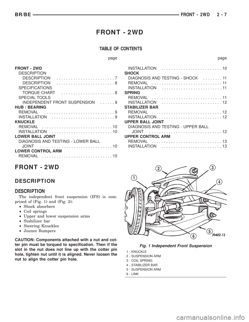
The independent front suspension (IFS) is com-
prised of (Fig. 1) and (Fig. 2):
²Shock absorbers
²Coil springs
²Upper and lower suspension arms
²Stabilizer bar
²Steering Knuckles
²Jounce Bumpers
CAUTION: Components attached with a nut and cot-
ter pin must be torqued to specification. Then if the
slot in the nut does not line up with the cotter pin
hole, tighten nut until it is aligned. Never loosen the
nut to align the cotter pin hole.
Fig. 1 Independent Front Suspension
1 - KNUCKLE
2 - SUSPENSION ARM
3 - COIL SPRING
4 - STABILIZER BAR
5 - SUSPENSION ARM
6 - LINK
BR/BEFRONT - 2WD 2 - 7
Page 33 of 2255

CAUTION: Suspension components with rubber/ure-
thane bushings (except stabilizer bar) should be
tightened with the vehicle at normal ride height. It is
important to have the springs supporting the weight
of the vehicle when the fasteners are torqued. If
springs are not at their normal ride position, vehicle
ride comfort could be affected and premature bush-
ing wear may occur.
DESCRIPTION
The upper suspension arm bolts on frame brackets
through the arm pivot shaft. The frame brackets
have slotted holes which allow the arms to be
adjusted for caster and camber. Pivot shaft bushings
are not replaceable.
The lower suspension arms bolt to the lower frame
brackets and pivot through bushings, these bushings
are not replaceable.
The suspension arms have lube for life riveted ball
studs.
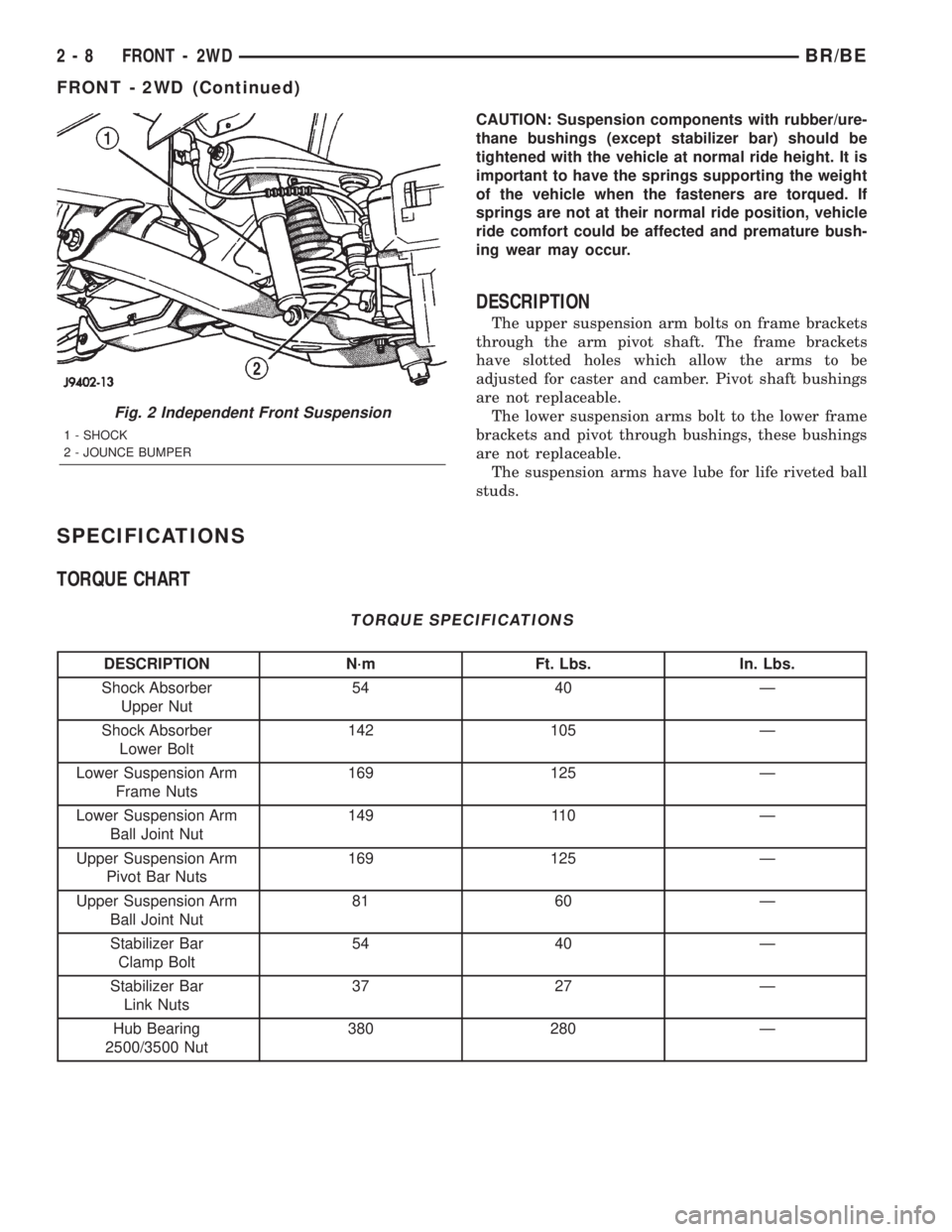
SPECIFICATIONS
TORQUE CHART
TORQUE SPECIFICATIONS
DESCRIPTION N´m Ft. Lbs. In. Lbs.
Shock Absorber
Upper Nut54 40 Ð
Shock Absorber
Lower Bolt142 105 Ð
Lower Suspension Arm
Frame Nuts169 125 Ð
Lower Suspension Arm
Ball Joint Nut149 110 Ð
Upper Suspension Arm
Pivot Bar Nuts169 125 Ð
Upper Suspension Arm
Ball Joint Nut81 60 Ð
Stabilizer Bar
Clamp Bolt54 40 Ð
Stabilizer Bar
Link Nuts37 27 Ð
Hub Bearing
2500/3500 Nut380 280 Ð
Fig. 2 Independent Front Suspension
1 - SHOCK
2 - JOUNCE BUMPER
2 - 8 FRONT - 2WDBR/BE
FRONT - 2WD (Continued)
Page 39 of 2255

FRONT - 4WD
TABLE OF CONTENTS
page page
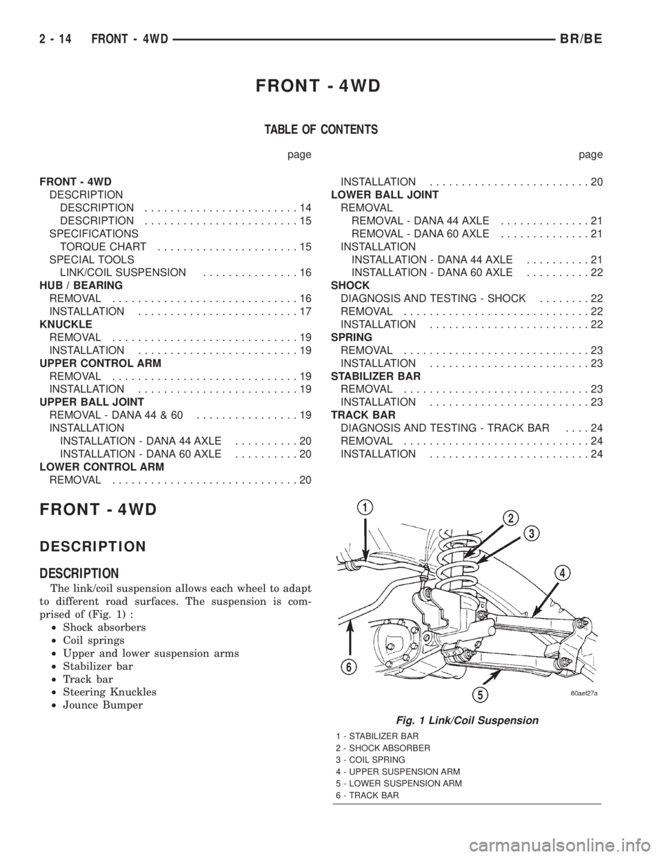
FRONT - 4WD
DESCRIPTION
DESCRIPTION........................14
DESCRIPTION........................15
SPECIFICATIONS
TORQUE CHART......................15
SPECIAL TOOLS
LINK/COIL SUSPENSION...............16
HUB / BEARING
REMOVAL.............................16
INSTALLATION.........................17
KNUCKLE
REMOVAL.............................19
INSTALLATION.........................19
UPPER CONTROL ARM
REMOVAL.............................19
INSTALLATION.........................19
UPPER BALL JOINT
REMOVAL - DANA 44 & 60................19
INSTALLATION
INSTALLATION - DANA 44 AXLE..........20
INSTALLATION - DANA 60 AXLE..........20
LOWER CONTROL ARM
REMOVAL.............................20INSTALLATION.........................20
LOWER BALL JOINT
REMOVAL
REMOVAL - DANA 44 AXLE..............21
REMOVAL - DANA 60 AXLE..............21
INSTALLATION
INSTALLATION - DANA 44 AXLE..........21
INSTALLATION - DANA 60 AXLE..........22
SHOCK
DIAGNOSIS AND TESTING - SHOCK........22
REMOVAL.............................22
INSTALLATION.........................22
SPRING
REMOVAL.............................23
INSTALLATION.........................23
STABILIZER BAR
REMOVAL.............................23
INSTALLATION.........................23
TRACK BAR
DIAGNOSIS AND TESTING - TRACK BAR....24
REMOVAL.............................24
INSTALLATION.........................24
FRONT - 4WD
DESCRIPTION
DESCRIPTION
The link/coil suspension allows each wheel to adapt
to different road surfaces. The suspension is com-
prised of (Fig. 1) :
²Shock absorbers
²Coil springs
²Upper and lower suspension arms
²Stabilizer bar
²Track bar
²Steering Knuckles
²Jounce Bumper
Fig. 1 Link/Coil Suspension
1 - STABILIZER BAR
2 - SHOCK ABSORBER
3 - COIL SPRING
4 - UPPER SUSPENSION ARM
5 - LOWER SUSPENSION ARM
6 - TRACK BAR
2 - 14 FRONT - 4WDBR/BE
Page 40 of 2255

CAUTION: Components attached with a nut and cot-
ter pin must be torqued to specification. Then if the
slot in the nut does not line up with the cotter pin
hole, tighten nut until it is aligned. Never loosen the
nut to align the cotter pin hole.
CAUTION: Suspension components with rubber
bushings (except stabilizer bar) should be tightened
with the vehicle at normal height. It is important to
have the springs supporting the weight of the vehi-
cle when the fasteners are torqued. If springs arenot at their normal ride position, vehicle ride com-
fort could be affected and premature bushing wear
may occur.
DESCRIPTION
The upper and lower suspension arms use bush-
ings to isolate road noise. The suspension arms are
bolted to the frame and axle through the rubber
bushings. The lower suspension arm uses cam bolts
at the axle to allow for caster and pinion angle
adjustment.
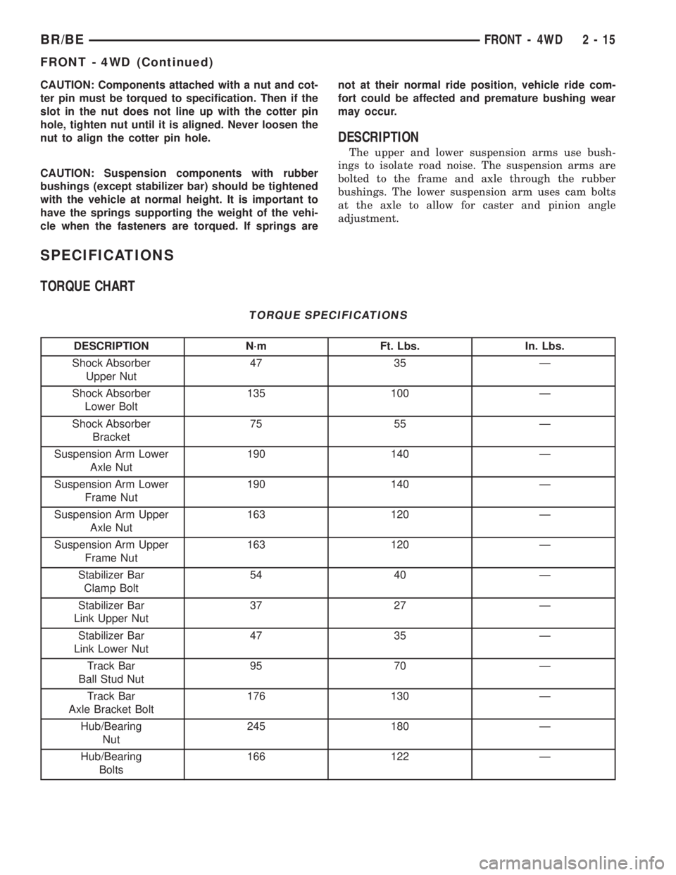
SPECIFICATIONS
TORQUE CHART
TORQUE SPECIFICATIONS
DESCRIPTION N´m Ft. Lbs. In. Lbs.
Shock Absorber
Upper Nut47 35 Ð
Shock Absorber
Lower Bolt135 100 Ð
Shock Absorber
Bracket75 55 Ð
Suspension Arm Lower
Axle Nut190 140 Ð
Suspension Arm Lower
Frame Nut190 140 Ð
Suspension Arm Upper
Axle Nut163 120 Ð
Suspension Arm Upper
Frame Nut163 120 Ð
Stabilizer Bar
Clamp Bolt54 40 Ð
Stabilizer Bar
Link Upper Nut37 27 Ð
Stabilizer Bar
Link Lower Nut47 35 Ð
Track Bar
Ball Stud Nut95 70 Ð
Track Bar
Axle Bracket Bolt176 130 Ð
Hub/Bearing
Nut245 180 Ð
Hub/Bearing
Bolts166 122 Ð
BR/BEFRONT - 4WD 2 - 15
FRONT - 4WD (Continued)
Page 44 of 2255

KNUCKLE
REMOVAL
(1) Remove hub bearing and axle shaft.
(2) Remove tie-rod or drag link end from the steer-
ing knuckle arm.
(3) Remove the ABS sensor wire and bracket from
knuckle. Refer to Brakes, for proper procedures.
(4) Remove the cotter pin from the upper ball stud
nut. Remove the upper and lower ball stud nuts.
(5) Strike the steering knuckle with a brass ham-
mer to loosen.
(6) Remove knuckle from axle tube yokes.
INSTALLATION
(1) Position the steering knuckle on the ball studs.
(2) Install and tighten lower ball stud nut to 47
N´m (35 ft. lbs.) torque. Do not install cotter pin at
this time.
(3) Install and tighten upper ball stud nut to 94
N´m (70 ft. lbs.) torque. Advance nut to next slot to
line up hole and install new cotter pin.
(4) Retorque lower ball stud nut to 190±217 N´m
(140±160 ft. lbs.) torque. Advance nut to next slot to
line up hole and install new cotter pin.
(5) Install the hub bearing and axle shaft.
(6) Install tie-rod or drag link end onto the steer-
ing knuckle arm.
(7) Install the ABS sensor wire and bracket to the
knuckle. Refer to Brakes, for proper procedure.
UPPER CONTROL ARM
REMOVAL
(1) Raise and support the vehicle.
(2) Remove the upper suspension arm nut and bolt
at the axle bracket (Fig. 12).
(3) Remove the nut and bolt at the frame rail and
remove the upper suspension arm.
INSTALLATION
(1) Position the upper suspension arm at the axle
and frame rail.
(2) Install the bolts and finger tighten the nuts.
(3) Remove the supports and lower the vehicle.
(4) Tighten nut at the axle bracket to 163 N´m
(120 ft. lbs.). Tighten nut at frame bracket to 163
N´m (120 ft. lbs.).
UPPER BALL JOINT
REMOVAL - DANA 44 & 60
(1) Position tools as shown to remove upper ball
stud (Fig. 13).
Fig. 12 Upper and Lower Suspension Arm
1 - STABILIZER BAR
2 - SHOCK ABSORBER
3 - COIL SPRING
4 - UPPER SUSPENSION ARM
5 - LOWER SUSPENSION ARM
6 - TRACK BAR
Fig. 13 UPPER BALL JOINT REMOVAL
1 - SPECIAL TOOL C4212-F
2 - SPECIAL TOOL 6761
3 - KNUCKLE
4 - SPECIAL TOOL 8445-3
BR/BEFRONT - 4WD 2 - 19