2002 DODGE RAM lock
[x] Cancel search: lockPage 1440 of 2255
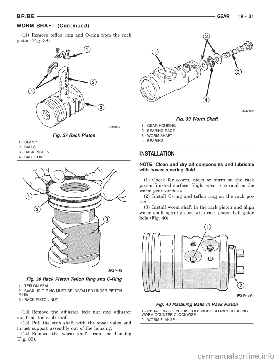
(11) Remove teflon ring and O-ring from the rack
piston (Fig. 38).
(12) Remove the adjuster lock nut and adjuster
nut from the stub shaft.
(13) Pull the stub shaft with the spool valve and
thrust support assembly out of the housing.
(14) Remove the worm shaft from the housing
(Fig. 39).
INSTALLATION
NOTE: Clean and dry all components and lubricate
with power steering fluid.
(1) Check for scores, nicks or burrs on the rack
piston finished surface. Slight wear is normal on the
worm gear surfaces.
(2) Install O-ring and teflon ring on the rack pis-
ton.
(3) Install worm shaft in the rack piston and align
worm shaft spiral groove with rack piston ball guide
hole (Fig. 40).
Fig. 37 Rack Piston
1 - CLAMP
2 - BALLS
3 - RACK PISTON
4 - BALL GUIDE
Fig. 38 Rack Piston Teflon Ring and O-Ring
1 - TEFLON SEAL
2 - BACK-UP O-RING MUST BE INSTALLED UNDER PISTON
RING
3 - RACK PISTON NUT
Fig. 39 Worm Shaft
1 - GEAR HOUSING
2 - BEARING RACE
3 - WORM SHAFT
4 - BEARING
Fig. 40 Installing Balls in Rack Piston
1 - INSTALL BALLS IN THIS HOLE WHILE SLOWLY ROTATING
WORM COUNTER CLOCKWISE
2 - WORM FLANGE
BR/BEGEAR 19 - 31
WORM SHAFT (Continued)
Page 1441 of 2255
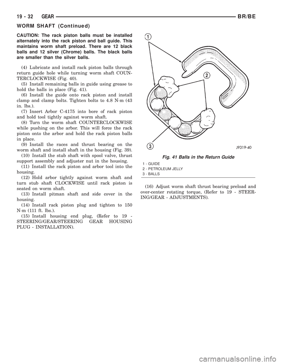
CAUTION: The rack piston balls must be installed
alternately into the rack piston and ball guide. This
maintains worm shaft preload. There are 12 black
balls and 12 silver (Chrome) balls. The black balls
are smaller than the silver balls.
(4) Lubricate and install rack piston balls through
return guide hole while turning worm shaft COUN-
TERCLOCKWISE (Fig. 40).
(5) Install remaining balls in guide using grease to
hold the balls in place (Fig. 41).
(6) Install the guide onto rack piston and install
clamp and clamp bolts. Tighten bolts to 4.8 N´m (43
in. lbs.).
(7) Insert Arbor C-4175 into bore of rack piston
and hold tool tightly against worm shaft.
(8) Turn the worm shaft COUNTERCLOCKWISE
while pushing on the arbor. This will force the rack
piston onto the arbor and hold the rack piston balls
in place.
(9) Install the races and thrust bearing on the
worm shaft and install shaft in the housing (Fig. 39).
(10) Install the stub shaft with spool valve, thrust
support assembly and adjuster nut in the housing.
(11) Install the rack piston and arbor tool into the
housing.
(12) Hold arbor tightly against worm shaft and
turn stub shaft CLOCKWISE until rack piston is
seated on worm shaft.
(13) Install pitman shaft and side cover in the
housing.
(14) Install rack piston plug and tighten to 150
N´m (111 ft. lbs.).
(15) Install housing end plug, (Refer to 19 -
STEERING/GEAR/STEERING GEAR HOUSING
PLUG - INSTALLATION).(16) Adjust worm shaft thrust bearing preload and
over-center rotating torque, (Refer to 19 - STEER-
ING/GEAR - ADJUSTMENTS).
Fig. 41 Balls in the Return Guide
1 - GUIDE
2 - PETROLEUM JELLY
3 - BALLS
19 - 32 GEARBR/BE
WORM SHAFT (Continued)
Page 1443 of 2255
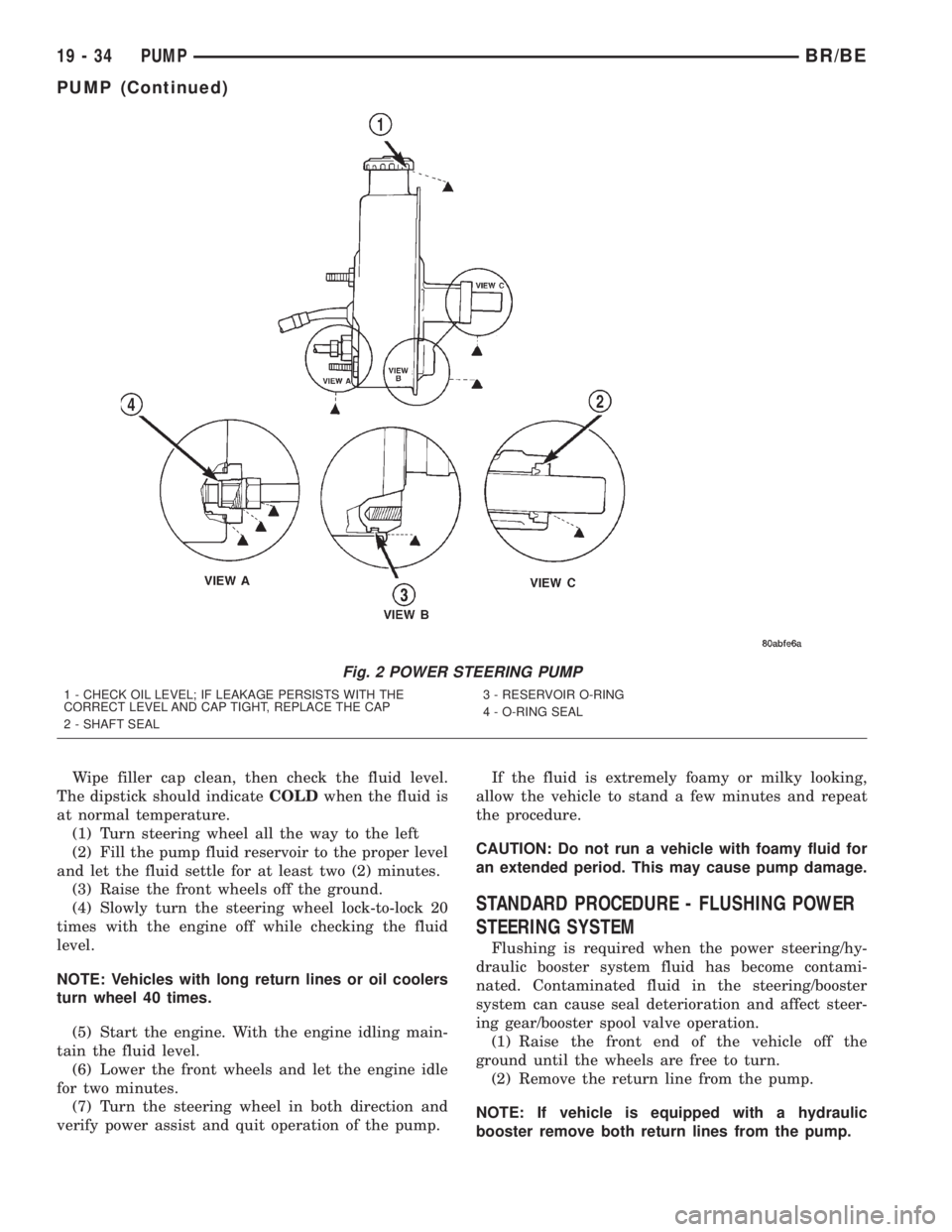
Wipe filler cap clean, then check the fluid level.
The dipstick should indicateCOLDwhen the fluid is
at normal temperature.
(1) Turn steering wheel all the way to the left
(2) Fill the pump fluid reservoir to the proper level
and let the fluid settle for at least two (2) minutes.
(3) Raise the front wheels off the ground.
(4) Slowly turn the steering wheel lock-to-lock 20
times with the engine off while checking the fluid
level.
NOTE: Vehicles with long return lines or oil coolers
turn wheel 40 times.
(5) Start the engine. With the engine idling main-
tain the fluid level.
(6) Lower the front wheels and let the engine idle
for two minutes.
(7) Turn the steering wheel in both direction and
verify power assist and quit operation of the pump.If the fluid is extremely foamy or milky looking,
allow the vehicle to stand a few minutes and repeat
the procedure.
CAUTION: Do not run a vehicle with foamy fluid for
an extended period. This may cause pump damage.
STANDARD PROCEDURE - FLUSHING POWER
STEERING SYSTEM
Flushing is required when the power steering/hy-
draulic booster system fluid has become contami-
nated. Contaminated fluid in the steering/booster
system can cause seal deterioration and affect steer-
ing gear/booster spool valve operation.
(1) Raise the front end of the vehicle off the
ground until the wheels are free to turn.
(2) Remove the return line from the pump.
NOTE: If vehicle is equipped with a hydraulic
booster remove both return lines from the pump.
Fig. 2 POWER STEERING PUMP
1 - CHECK OIL LEVEL; IF LEAKAGE PERSISTS WITH THE
CORRECT LEVEL AND CAP TIGHT, REPLACE THE CAP
2 - SHAFT SEAL3 - RESERVOIR O-RING
4 - O-RING SEAL
19 - 34 PUMPBR/BE
PUMP (Continued)
Page 1444 of 2255
(3) Plug the return line port/ports at the pump.
(4) Position the return line/lines into a large con-
tainer to catch the fluid.
(5) While an assistant is filling the pump reservoir
start the engine.
(6) With the engine running at idle turn the wheel
back and forth.
NOTE: Do not contact or hold the wheel against the
steering stops.
(7) Run a quart of fluid through the system then
stop the engine and install the return line/lines.
(8) Fill the system with fluid and perform Steering
Pump Initial Operation, (Refer to 19 - STEERING/
PUMP - STANDARD PROCEDURE).
(9) Start the engine and run it for fifteen minutes
then stop the engine.
(10) Remove the return line/lines from the pump
and plug the pump port/ports.
(11) Pour fresh fluid into the reservoir and check
the draining fluid for contamination. If the fluid is
still contaminated, disassemble and clean the steer-
ing gear and flush the system again.
(12) Install the return line/lines and perform
Steering Pump Initial Operation, (Refer to 19 -
STEERING/PUMP - STANDARD PROCEDURE).
REMOVAL
REMOVAL - GASOLINE ENGINE
(1) Remove the serpentine drive belt, (Refer to 7 -
COOLING/ACCESSORY DRIVE/DRIVE BELTS -
REMOVAL) OR (Refer to 7 - COOLING/ACCESSORY
DRIVE/DRIVE BELTS - REMOVAL).
(2) Remove the hoses from the power steering
pump and cap the fittings.
(3) Remove battery ground cable and unthread
stud from cylinder head, do not remove from bracket.
(4) Loosen upper bracket bolt and remove the
lower bracket to engine block bolts.
(5) Pivot the pump assembly past the coolant tube.
(6) Remove the upper stud and remove upper bolt
from cylinder head.
(7) Remove steering pump and mounting bracket
from engine as an assembly.
(8) Remove the pump pulley with Puller C-4333, to
access pump attaching bolts, (Refer to 19 - STEER-
ING/PUMP/PULLEY - REMOVAL).
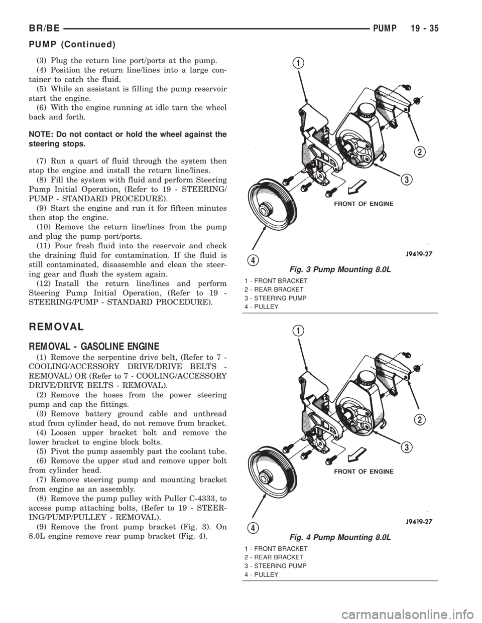
(9) Remove the front pump bracket (Fig. 3). On
8.0L engine remove rear pump bracket (Fig. 4).
Fig. 3 Pump Mounting 8.0L
1 - FRONT BRACKET
2 - REAR BRACKET
3 - STEERING PUMP
4 - PULLEY
Fig. 4 Pump Mounting 8.0L
1 - FRONT BRACKET
2 - REAR BRACKET
3 - STEERING PUMP
4 - PULLEY
BR/BEPUMP 19 - 35
PUMP (Continued)
Page 1445 of 2255
REMOVAL - DIESEL ENGINE
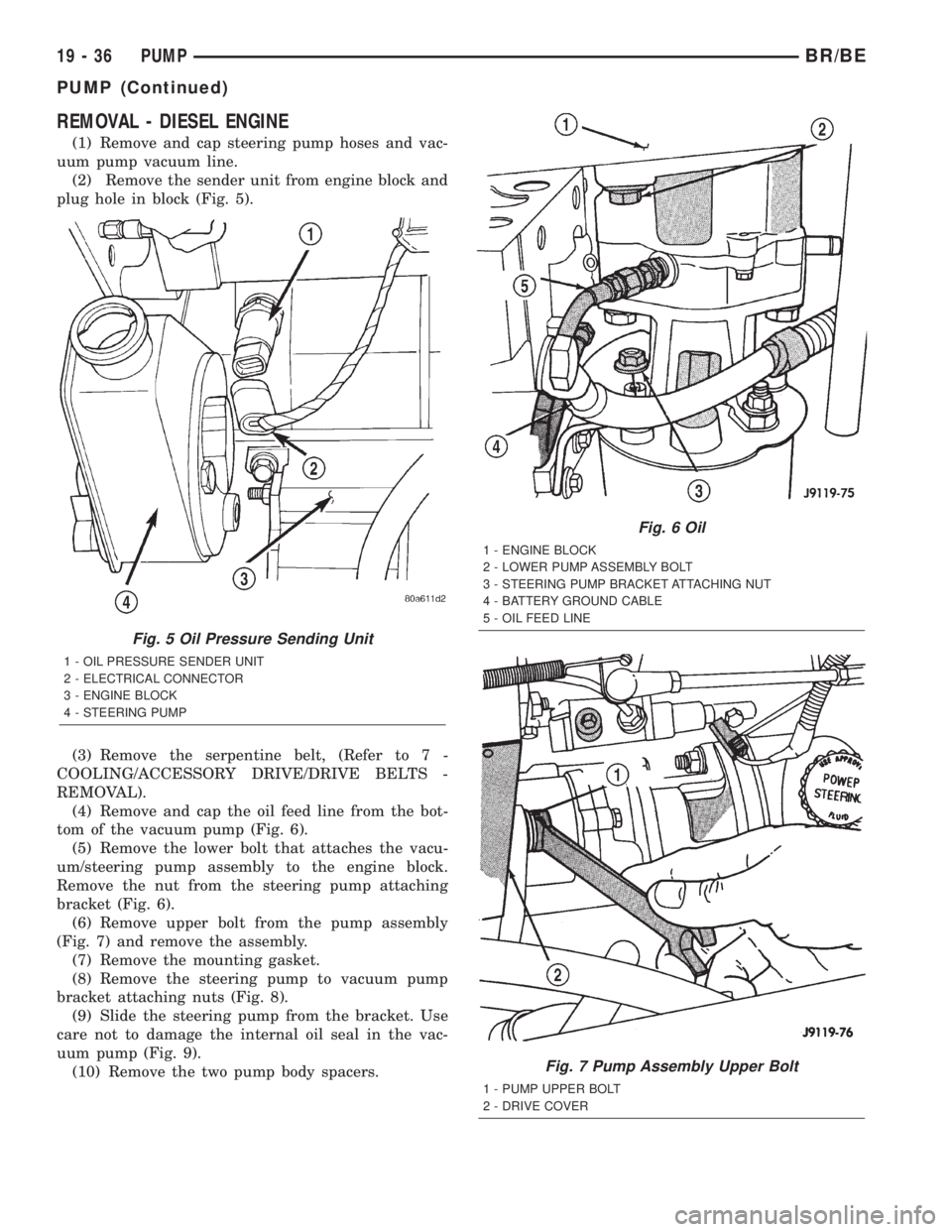
(1) Remove and cap steering pump hoses and vac-
uum pump vacuum line.
(2) Remove the sender unit from engine block and
plug hole in block (Fig. 5).
(3) Remove the serpentine belt, (Refer to 7 -
COOLING/ACCESSORY DRIVE/DRIVE BELTS -
REMOVAL).
(4) Remove and cap the oil feed line from the bot-
tom of the vacuum pump (Fig. 6).
(5) Remove the lower bolt that attaches the vacu-
um/steering pump assembly to the engine block.
Remove the nut from the steering pump attaching
bracket (Fig. 6).
(6) Remove upper bolt from the pump assembly
(Fig. 7) and remove the assembly.
(7) Remove the mounting gasket.
(8) Remove the steering pump to vacuum pump
bracket attaching nuts (Fig. 8).
(9) Slide the steering pump from the bracket. Use
care not to damage the internal oil seal in the vac-
uum pump (Fig. 9).
(10) Remove the two pump body spacers.
Fig. 5 Oil Pressure Sending Unit
1 - OIL PRESSURE SENDER UNIT
2 - ELECTRICAL CONNECTOR
3 - ENGINE BLOCK
4 - STEERING PUMP
Fig. 6 Oil
1 - ENGINE BLOCK
2 - LOWER PUMP ASSEMBLY BOLT
3 - STEERING PUMP BRACKET ATTACHING NUT
4 - BATTERY GROUND CABLE
5 - OIL FEED LINE
Fig. 7 Pump Assembly Upper Bolt
1 - PUMP UPPER BOLT
2 - DRIVE COVER
19 - 36 PUMPBR/BE
PUMP (Continued)
Page 1446 of 2255
INSTALLATION
INSTALLATION - GASOLINE ENGINE
(1) Install the front pump bracket and tighten
bolts to 47 N´m (35 ft. lbs.). On 8.0L engine install
rear pump bracket and tighten nut to 47 N´m (35 ft.
lbs.), tighten bolts to 24 N´m (18 ft. lbs.).
(2) Install the pump pulley with Installer
C-4063±B, (Refer to 19 - STEERING/PUMP/PULLEY
- INSTALLATION).
(3) Install steering pump assembly on the engine
block. Install the upper stud and bolt in bracket.
(4) Pivot the pump down past the coolant tube and
install the lower bolts in bracket.
(5) Tighten the bolts and nut to 41 N´m (30 ft.
lbs.).
(6) Connect the hoses to the pump.
(7) Install the serpentine drive belt, (Refer to 7 -
COOLING/ACCESSORY DRIVE/DRIVE BELTS -
INSTALLATION), (Refer to 7 - COOLING/ACCES-
SORY DRIVE/DRIVE BELTS - INSTALLATION).
(8) Fill the reservoir with power steering fluid,
(Refer to 19 - STEERING/PUMP - STANDARD PRO-
CEDURE).
INSTALLATION - DIESEL ENGINE
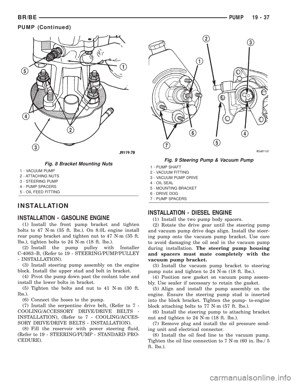
(1) Install the two pump body spacers.
(2) Rotate the drive gear until the steering pump
and vacuum pump drive dogs align. Install the steer-
ing pump onto the vacuum pump bracket. Use care
to avoid damaging the oil seal in the vacuum pump
during installation.The steering pump housing
and spacers must mate completely with the
vacuum pump bracket.
(3) Install the vacuum pump bracket to steering
pump nuts and tighten to 24 N´m (18 ft. lbs.).
(4) Position new gasket on vacuum pump assem-
bly. Use sealer if necessary to retain the gasket.
(5) Align and install the pump assembly on the
engine. Ensure the steering pump stud is inserted
into the block bracket. Tighten the pump- to-engine
block attaching bolts to 77 N´m (57 ft. lbs.).
(6) Install the steering pump to attaching bracket
nut and tighten to 24 N´m (18 ft. lbs.).
(7) Remove plug and install the oil pressure send-
ing unit and electrical connector.
(8) Install the oil feed line to the vacuum pump.
Tighten the oil line connection to 7 N´m (60 in. lbs./ 5
ft. lbs.).
Fig. 8 Bracket Mounting Nuts
1 - VACUUM PUMP
2 - ATTACHING NUTS
3 - STEERING PUMP
4 - PUMP SPACERS
5 - OIL FEED FITTING
Fig. 9 Steering Pump & Vacuum Pump
1 - PUMP SHAFT
2 - VACUUM FITTING
3 - VACUUM PUMP DRIVE
4 - OIL SEAL
5 - MOUNTING BRACKET
6 - DRIVE DOG
7 - PUMP SPACERS
BR/BEPUMP 19 - 37
PUMP (Continued)
Page 1450 of 2255
INSTALLATION
(1) Position idler arm on the frame bracket and
tighten the bolt to specification.
(2) Center steering gear to alignment marks and
install pitman arm.
(3)
Install the lock washer and retaining nut on the
pitman shaft. Tighten the nut to 251 N´m (185 ft. lbs.).
(4) Install center link to ball studs and tighten
retaining nuts to specification.
(5) Install tie-rod ends into center link and tighten
the nuts to 88 N´m (65 ft. lbs.). Install new nuts.(6) Install tie-rod ends into steering knuckles and
tighten nuts to 108 N´m (80 ft. lbs.).
(7) Remove the supports and lower the vehicle to
the surface. Center steering wheel and adjust toe,
(Refer to 2 - SUSPENSION/WHEEL ALIGNMENT -
STANDARD PROCEDURE).
NOTE: Position the clamp on the sleeve so retain-
ing bolt is located on the bottom side of the sleeve.
(8) After adjustment, tighten the tie-rod adjust-
ment sleeve clamp bolt to 61 N´m (45 ft. lbs.).
SPECIFICATIONS
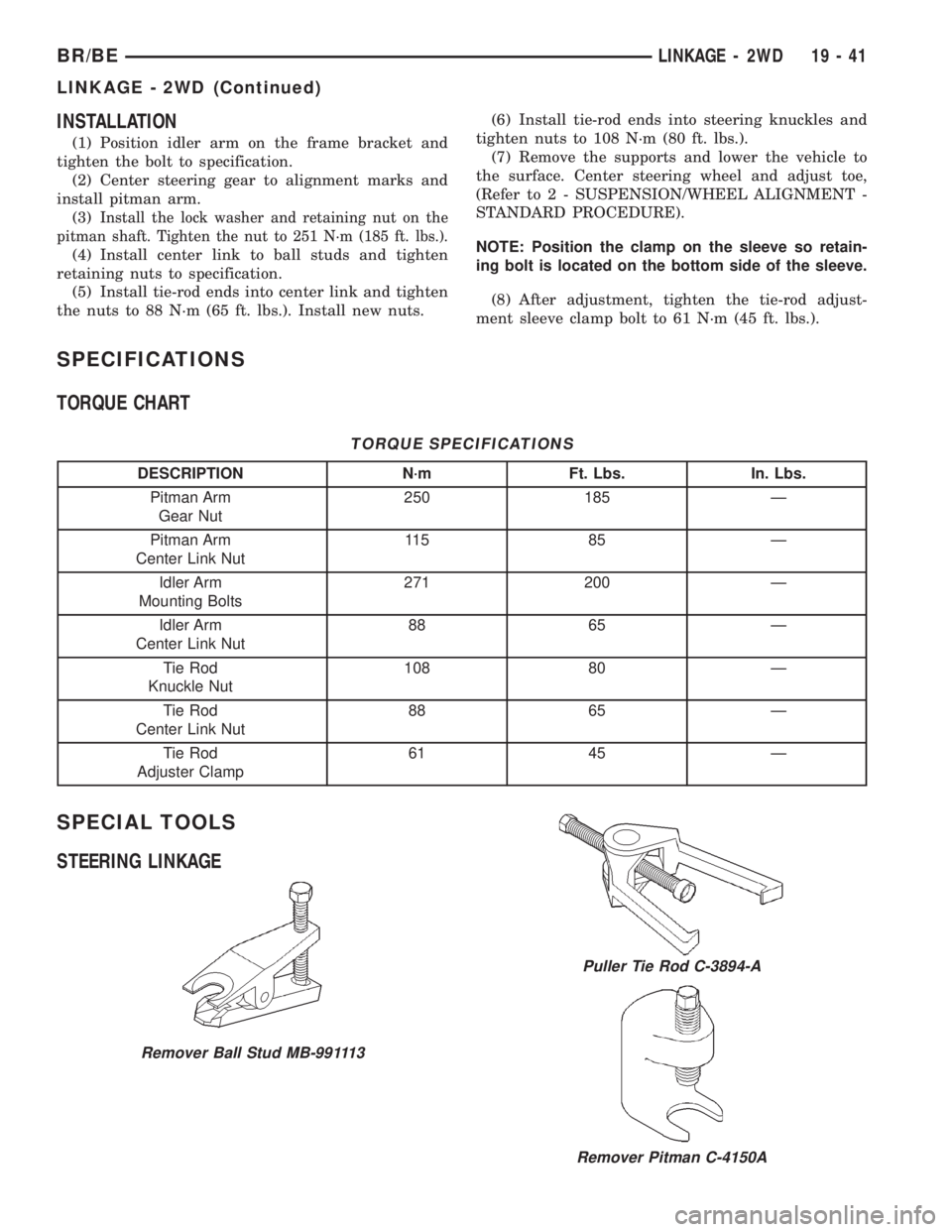
TORQUE CHART
TORQUE SPECIFICATIONS
DESCRIPTION N´m Ft. Lbs. In. Lbs.
Pitman Arm
Gear Nut250 185 Ð
Pitman Arm
Center Link Nut11 5 8 5 Ð
Idler Arm
Mounting Bolts271 200 Ð
Idler Arm
Center Link Nut88 65 Ð
Tie Rod
Knuckle Nut108 80 Ð
Tie Rod
Center Link Nut88 65 Ð
Tie Rod
Adjuster Clamp61 45 Ð
SPECIAL TOOLS
STEERING LINKAGE
Remover Ball Stud MB-991113
Puller Tie Rod C-3894-A
Remover Pitman C-4150A
BR/BELINKAGE - 2WD 19 - 41
LINKAGE - 2WD (Continued)
Page 1452 of 2255
(6) Mark the pitman arm and shaft positions for
installation reference. Remove the nut and washer
from the pitman arm. Remove the pitman arm with
Puller C-4150A.
INSTALLATION
(1) Align reference marks and install pitman arm.
(2) Install the lock washer and retaining nut on
the pitman shaft and tighten nut to 251 N´m (185 ft.
lbs.).
(3) Install drag link to the pitman arm. Install the
nut and tighten to 108 N´m (80 ft. lbs.).
(4) Install drag link to the right steering knuckle.
Install the nut and tighten to 88 N´m (65 ft. lbs.).
(5) Install tie rod to the left steering knuckle and
drag link. Install the nuts and tighten to 108 N´m
(80 ft. lbs.).(6) Install steering damper on the axle. Tighten
nut to 95 N´m (75 ft. lbs.).
(7) Install steering damper on the tie rod. Tighten
nut to 81 N´m (60 ft. lbs.).
(8) Remove the supports and lower the vehicle to
the surface. Center steering wheel and adjust toe,
refer to Group 2 Suspension.
(9) After adjustment tighten tie rod adjustment
sleeve clamp bolts to 61 N´m (45 ft. lbs.).
NOTE: Position the clamp on the sleeve so retain-
ing bolt is located on the bottom side of the sleeve.
SPECIFICATIONS
TORQUE CHART
TORQUE SPECIFICATIONS
DESCRIPTION N´m Ft. Lbs. In. Lbs.
Pitman Arm
Gear Shaft251 185 Ð
Drag Link
Pitman Arm108 80 Ð
Drag Link
Tie Rod88 65 Ð
Drag Link
Adjuster Clamp61 45 Ð
Tie Rod End
Knuckle108 80 Ð
Tie Rod End
Adjuster Clamp61 45 Ð
Steering Damper
Axle95 70 Ð
Steering Damper
Tie Rod81 60 Ð
BR/BELINKAGE - 4WD 19 - 43
LINKAGE - 4WD (Continued)