2002 DODGE RAM instrument panel
[x] Cancel search: instrument panelPage 1671 of 2255
The valve is serviced as an assembly; it is not
repairable. Do not clean the valve if restricted, or
contaminated by sludge, or debris. If the valve fails,
or if a transmission malfunction occurs that gener-
ates significant amounts of sludge and/or clutch par-
ticles and metal shavings, the valve must be
replaced.
The valve must be removed whenever the cooler
and lines are reverse flushed. The valve can be flow
tested when necessary. The procedure is exactly the
same as for flow testing a cooler.
If the valve is restricted, installed backwards, or in
the wrong line, it will cause an overheating condition
and possible transmission failure.
CAUTION: The drainback valve is a one-way flow
device. It must be properly oriented in terms of flow
direction for the cooler to function properly. The
valve must be installed in the pressure line. Other-
wise flow will be blocked and would cause an over-
heating condition and eventual transmission failure.
TRANSMISSION
TEMPERATURE SENSOR
DESCRIPTION
Transmission fluid temperature readings are sup-
plied to the transmission control module by the ther-
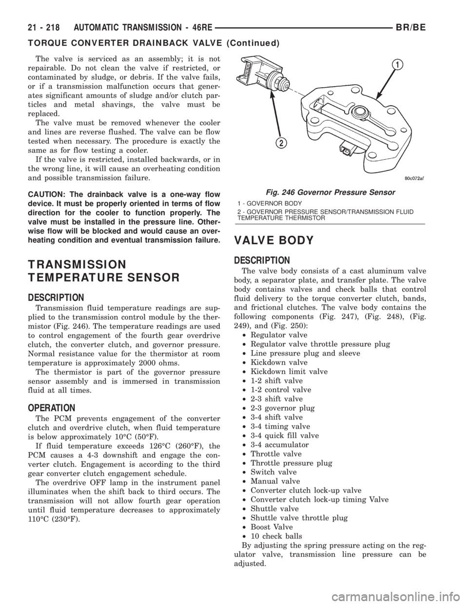
mistor (Fig. 246). The temperature readings are used
to control engagement of the fourth gear overdrive
clutch, the converter clutch, and governor pressure.
Normal resistance value for the thermistor at room
temperature is approximately 2000 ohms.
The thermistor is part of the governor pressure
sensor assembly and is immersed in transmission
fluid at all times.
OPERATION
The PCM prevents engagement of the converter
clutch and overdrive clutch, when fluid temperature
is below approximately 10ÉC (50ÉF).
If fluid temperature exceeds 126ÉC (260ÉF), the
PCM causes a 4-3 downshift and engage the con-
verter clutch. Engagement is according to the third
gear converter clutch engagement schedule.
The overdrive OFF lamp in the instrument panel
illuminates when the shift back to third occurs. The
transmission will not allow fourth gear operation
until fluid temperature decreases to approximately
110ÉC (230ÉF).
VALVE BODY
DESCRIPTION
The valve body consists of a cast aluminum valve
body, a separator plate, and transfer plate. The valve
body contains valves and check balls that control
fluid delivery to the torque converter clutch, bands,
and frictional clutches. The valve body contains the
following components (Fig. 247), (Fig. 248), (Fig.
249), and (Fig. 250):
²Regulator valve
²Regulator valve throttle pressure plug
²Line pressure plug and sleeve
²Kickdown valve
²Kickdown limit valve
²1-2 shift valve
²1-2 control valve
²2-3 shift valve
²2-3 governor plug
²3-4 shift valve
²3-4 timing valve
²3-4 quick fill valve
²3-4 accumulator
²Throttle valve
²Throttle pressure plug
²Switch valve
²Manual valve
²Converter clutch lock-up valve
²Converter clutch lock-up timing Valve
²Shuttle valve
²Shuttle valve throttle plug
²Boost Valve
²10 check balls
By adjusting the spring pressure acting on the reg-
ulator valve, transmission line pressure can be
adjusted.
Fig. 246 Governor Pressure Sensor
1 - GOVERNOR BODY
2 - GOVERNOR PRESSURE SENSOR/TRANSMISSION FLUID
TEMPERATURE THERMISTOR
21 - 218 AUTOMATIC TRANSMISSION - 46REBR/BE
TORQUE CONVERTER DRAINBACK VALVE (Continued)
Page 1844 of 2255
If fluid temperature exceeds 126ÉC (260ÉF), the
PCM causes a 4-3 downshift and engage the con-
verter clutch. Engagement is according to the third
gear converter clutch engagement schedule.
The overdrive OFF lamp in the instrument panel
illuminates when the shift back to third occurs. The
transmission will not allow fourth gear operation
until fluid temperature decreases to approximately
110ÉC (230ÉF).
VALVE BODY
DESCRIPTION
The valve body consists of a cast aluminum valve
body, a separator plate, and transfer plate. The valve
body contains valves and check balls that control
fluid delivery to the torque converter clutch, bands,
and frictional clutches. The valve body contains the
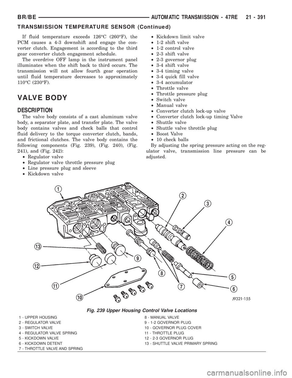
following components (Fig. 239), (Fig. 240), (Fig.
241), and (Fig. 242):
²Regulator valve
²Regulator valve throttle pressure plug
²Line pressure plug and sleeve
²Kickdown valve²Kickdown limit valve
²1-2 shift valve
²1-2 control valve
²2-3 shift valve
²2-3 governor plug
²3-4 shift valve
²3-4 timing valve
²3-4 quick fill valve
²3-4 accumulator
²Throttle valve
²Throttle pressure plug
²Switch valve
²Manual valve
²Converter clutch lock-up valve
²Converter clutch lock-up timing Valve
²Shuttle valve
²Shuttle valve throttle plug
²Boost Valve
²10 check balls
By adjusting the spring pressure acting on the reg-
ulator valve, transmission line pressure can be
adjusted.
Fig. 239 Upper Housing Control Valve Locations
1 - UPPER HOUSING 8 - MANUAL VALVE
2 - REGULATOR VALVE 9 - 1-2 GOVERNOR PLUG
3 - SWITCH VALVE 10 - GOVERNOR PLUG COVER
4 - REGULATOR VALVE SPRING 11 - THROTTLE PLUG
5 - KICKDOWN VALVE 12 - 2-3 GOVERNOR PLUG
6 - KICKDOWN DETENT 13 - SHUTTLE VALVE PRIMARY SPRING
7 - THROTTLE VALVE AND SPRING
BR/BEAUTOMATIC TRANSMISSION - 47RE 21 - 391
TRANSMISSION TEMPERATURE SENSOR (Continued)
Page 1968 of 2255
BODY
TABLE OF CONTENTS
page page
BODY
WARNING
SAFETY PRECAUTIONS AND WARNINGS . . . 1
DIAGNOSIS AND TESTING
DIAGNOSIS AND TESTING - WATER LEAKS . 2
DIAGNOSIS AND TESTING - WIND NOISE . . . 3
SPECIFICATIONS
WELD LOCATIONS.....................4
STRUCTURAL ADHESIVE LOCATIONS.....44
BODY SEALER LOCATIONS.............47
BODY GAP AND FLUSH MEASUREMENTS . . 56
BODY OPENING DIMENSIONS...........60TORQUE SPECIFICATIONS.............61
DECKLID/HATCH/LIFTGATE/TAILGATE.......63
DOOR - FRONT.........................68
DOOR - CARGO.........................77
EXTERIOR.............................86
HOOD................................100
INSTRUMENT PANEL SYSTEM............105
INTERIOR.............................118
PAINT................................129
SEATS...............................131
STATIONARY GLASS....................145
WEATHERSTRIP/SEALS..................151
BODY
WARNING
SAFETY PRECAUTIONS AND WARNINGS
WARNING: USE AN OSHA APPROVED BREATHING
FILTER WHEN SPRAYING PAINT OR SOLVENTS IN
A CONFINED AREA. PERSONAL INJURY CAN
RESULT.
²AVOID PROLONGED SKIN CONTACT WITH
PETROLEUM OR ALCOHOL ± BASED CLEANING
SOLVENTS. PERSONAL INJURY CAN RESULT.
²DO NOT STAND UNDER A HOISTED VEHICLE
THAT IS NOT PROPERLY SUPPORTED ON SAFETY
STANDS. PERSONAL INJURY CAN RESULT.CAUTION: When holes must be drilled or punched
in an inner body panel, verify depth of space to the
outer body panel, electrical wiring, or other compo-
nents. Damage to vehicle can result.
²Do not weld exterior panels unless combustible
material on the interior of vehicle is removed from
the repair area. Fire or hazardous conditions, can
result.
²Always have a fire extinguisher ready for use
when welding.
²Disconnect the negative (-) cable clamp from
the battery when servicing electrical components
that are live when the ignition is OFF. Damage to
electrical system can result.
²Do not use abrasive chemicals or compounds
on painted surfaces. Damage to finish can result.
²Do not use harsh alkaline based cleaning sol-
vents on painted or upholstered surfaces. Damage
to finish or color can result.
²Do not hammer or pound on plastic trim panel
when servicing interior trim. Plastic panels can
break.
BR/BEBODY 23 - 1
Page 2029 of 2255
Description N´m Ft. lbs. In. lbs.
Center seat/seat frame
bolts25 18 Ð
Cubby bin screws 2 Ð 20
Cup holder screws 2 Ð 20
Door hinge to A-pillar
bolt28 21 Ð
Door latch screw 11 8 Ð
Door latch striker screw 28 21 Ð
Easy entry track/
adjuster track bolts -
front17 12 Ð
Easy entry track/
adjuster track bolts -
rear inboard21 16 Ð
Easy entry track/
adjuster track bolts -
rear outboard45 33 Ð
Front belt buckle
inboard anchor nut45 33 Ð
Front belt retractor
anchor bolt39 28 Ð
Front door glass lift
plate nuts9Ð80
Front door latch screws 10 Ð 89
Front shoulder belt
anchor bolt45 33 Ð
Front shoulder belt
lower anchor bolt39 28 Ð
Front shoulder belt
lower anchor bolt45 33 Ð
Front shoulder belt
upper anchor bolt39 28 Ð
Glove box bin/door
screws2Ð20
Glove box latch striker
screws2Ð20
Glove box opening trim
screws2Ð20
Headlamp/dash wire
harness bulkhead
connector screw3.5 Ð 31
Hood latch release
handle screws3Ð25
Inboard seat back pivot
bolt50 36 Ð
Instrument panel roll
down bracket screws12 9 105Description N´m Ft. lbs. In. lbs.
Instrument panel top
cover screws2Ð20
Instrument panel/dash
panel screws3Ð28
Manual transmission
shifter knob nut27 20 Ð
Quarter vent window
hinge nuts8Ð70
Quarter vent window
latch to glass screws6Ð60
Rear seat support
bracket screws28 21 Ð
Rear view mirror set
screw1Ð15
Seat adjuster track/seat
cushion frame screws25 18 Ð
Seat cushion frame/
mounting bracket bolts25 18 Ð
Seat cushion frame/
power track crossbrace
bolts10 Ð 89
Seat track adjuster bolts 17 12 Ð
Seat track bolts 25 18 Ð
Seat track/frame bolts 25 18 Ð
Slide bar bolts 10 Ð 89
Sliding backlite
latch/keeper screws1.5 Ð 15
Split bench seat back
shoulder bolt49 36 Ð
Split bench seat back to
cushion pivot bolt25 18 Ð
Split bench seat front
anchor bolt54 40 Ð
Split bench seat rear
inboard anchor nut40 30 Ð
Split bench seat rear
outboard anchor nut54 40 Ð
Split bench seat track to
frame bolt25 18 Ð
Split bench/bottom of
center occupant seat
bolt28 21 Ð
Steering column cover
screws2Ð20
Storage bin screws 2 Ð 20
23 - 62 BODYBR/BE
BODY (Continued)
Page 2036 of 2255
(14) Inspect for air bubbles. Small bubbles can be
pierced with a sharp pin and smoothed out.
(15) Install outer belt weatherstrip (Refer to 23 -
BODY/WEATHERSTRIP/SEALS/FDR OUTER BELT
WEATHERSTRIP - INSTALLATION).
(16) Install glass run weatherstrip (Refer to 23 -
BODY/WEATHERSTRIP/SEALS/FDR GLASS RUN
WEATHERSTRIP - INSTALLATION).
DOOR
REMOVAL
(1) Remove cowl trim panel (Refer to 23 - BODY/
INTERIOR/COWL TRIM COVER - REMOVAL).
(2) Disengage door wire harness connector of
instrument panel harness and push door harness
through access hole in pillar.
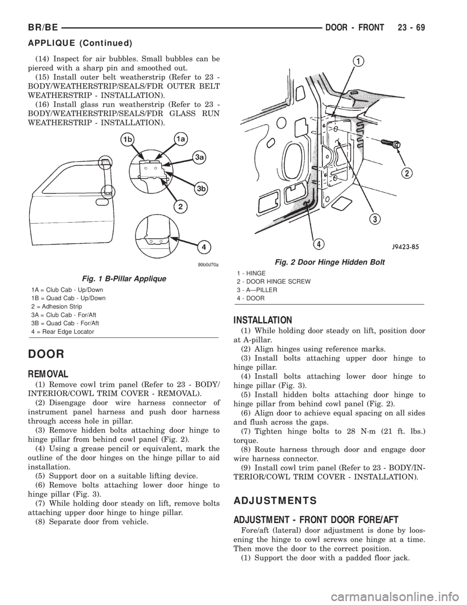
(3) Remove hidden bolts attaching door hinge to
hinge pillar from behind cowl panel (Fig. 2).
(4) Using a grease pencil or equivalent, mark the
outline of the door hinges on the hinge pillar to aid
installation.
(5) Support door on a suitable lifting device.
(6) Remove bolts attaching lower door hinge to
hinge pillar (Fig. 3).
(7) While holding door steady on lift, remove bolts
attaching upper door hinge to hinge pillar.
(8) Separate door from vehicle.
INSTALLATION
(1) While holding door steady on lift, position door
at A-pillar.
(2) Align hinges using reference marks.
(3) Install bolts attaching upper door hinge to
hinge pillar.
(4) Install bolts attaching lower door hinge to
hinge pillar (Fig. 3).
(5) Install hidden bolts attaching door hinge to
hinge pillar from behind cowl panel (Fig. 2).
(6) Align door to achieve equal spacing on all sides
and flush across the gaps.
(7) Tighten hinge bolts to 28 N´m (21 ft. lbs.)
torque.
(8) Route harness through door and engage door
wire harness connector.
(9) Install cowl trim panel (Refer to 23 - BODY/IN-
TERIOR/COWL TRIM COVER - INSTALLATION).
ADJUSTMENTS
ADJUSTMENT - FRONT DOOR FORE/AFT
Fore/aft (lateral) door adjustment is done by loos-
ening the hinge to cowl screws one hinge at a time.
Then move the door to the correct position.
(1) Support the door with a padded floor jack.
Fig. 1 B-Pillar Applique
1A = Club Cab - Up/Down
1B = Quad Cab - Up/Down
2 = Adhesion Strip
3A = Club Cab - For/Aft
3B = Quad Cab - For/Aft
4 = Rear Edge Locator
Fig. 2 Door Hinge Hidden Bolt
1 - HINGE
2 - DOOR HINGE SCREW
3 - AÐPILLER
4 - DOOR
BR/BEDOOR - FRONT 23 - 69
APPLIQUE (Continued)
Page 2070 of 2255
LATCH RELEASE CABLE
REMOVAL
(1) Remove hood latch (Refer to 23 - BODY/HOOD/
LATCH - REMOVAL).
(2) Disconnect release cable from hood latch.
(3) Detach the release cable from the retainer clips
in the engine compartment.
(4) Separate the release cable grommet from the
dash panel hole.
(5) From the inside of the vehicle, remove the
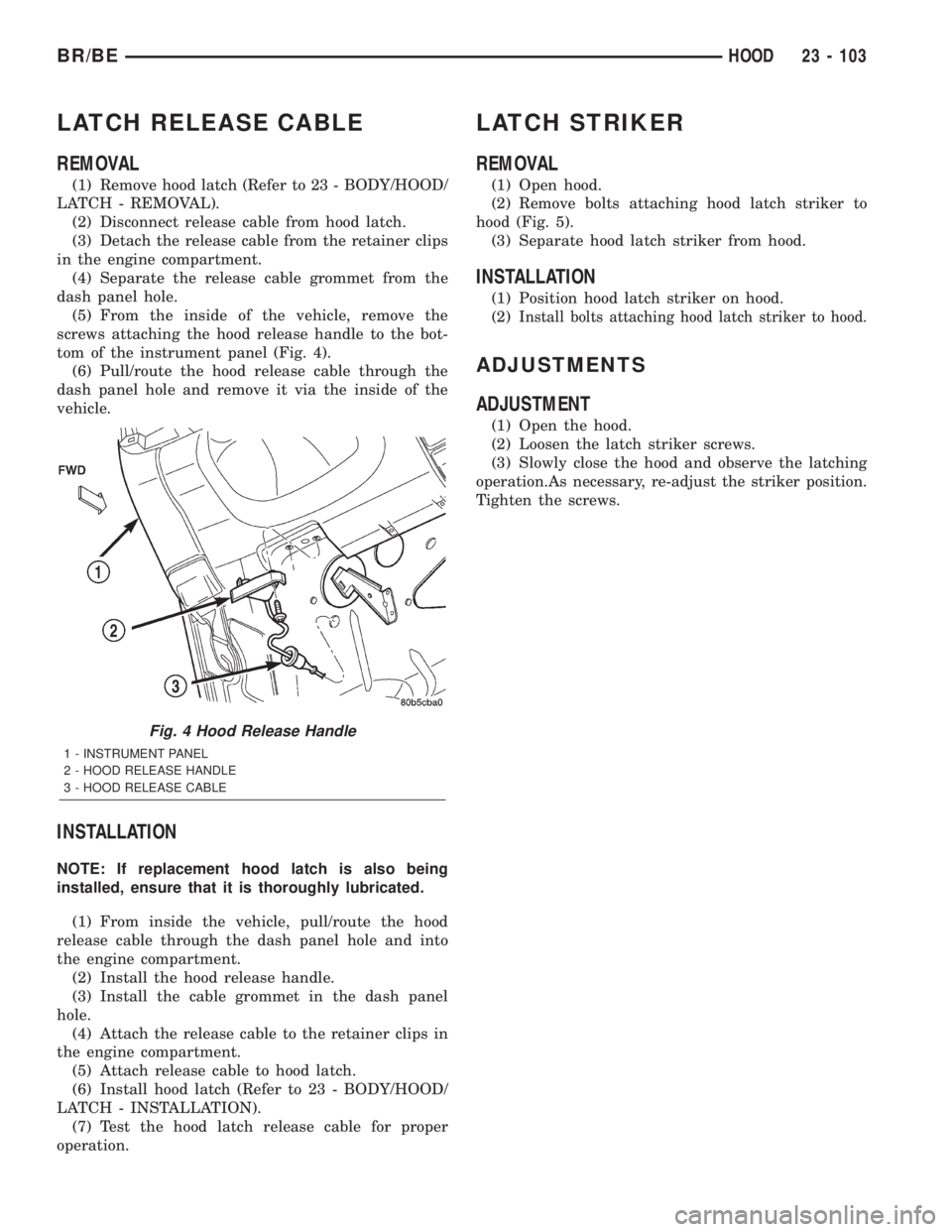
screws attaching the hood release handle to the bot-
tom of the instrument panel (Fig. 4).
(6) Pull/route the hood release cable through the
dash panel hole and remove it via the inside of the
vehicle.
INSTALLATION
NOTE: If replacement hood latch is also being
installed, ensure that it is thoroughly lubricated.
(1) From inside the vehicle, pull/route the hood
release cable through the dash panel hole and into
the engine compartment.
(2) Install the hood release handle.
(3) Install the cable grommet in the dash panel
hole.
(4) Attach the release cable to the retainer clips in
the engine compartment.
(5) Attach release cable to hood latch.
(6) Install hood latch (Refer to 23 - BODY/HOOD/
LATCH - INSTALLATION).
(7) Test the hood latch release cable for proper
operation.
LATCH STRIKER
REMOVAL
(1) Open hood.
(2) Remove bolts attaching hood latch striker to
hood (Fig. 5).
(3) Separate hood latch striker from hood.
INSTALLATION
(1) Position hood latch striker on hood.
(2)
Install bolts attaching hood latch striker to hood.
ADJUSTMENTS
ADJUSTMENT
(1) Open the hood.
(2) Loosen the latch striker screws.
(3) Slowly close the hood and observe the latching
operation.As necessary, re-adjust the striker position.
Tighten the screws.
Fig. 4 Hood Release Handle
1 - INSTRUMENT PANEL
2 - HOOD RELEASE HANDLE
3 - HOOD RELEASE CABLE
BR/BEHOOD 23 - 103
Page 2072 of 2255
INSTRUMENT PANEL SYSTEM
TABLE OF CONTENTS
page page
INSTRUMENT PANEL SYSTEM
DESCRIPTION........................105
OPERATION..........................106
ASH RECEIVER
REMOVAL............................107
INSTALLATION........................107
CLUSTER BEZEL
REMOVAL............................108
INSTALLATION........................108
CUBBY BIN
REMOVAL............................108
INSTALLATION........................109
CUP HOLDER
REMOVAL............................109
INSTALLATION........................110
GLOVE BOX
REMOVAL
REMOVAL..........................110
DISASSEMBLY - GLOVE BOX...........110
ASSEMBLY - GLOVE BOX................111INSTALLATION........................111
GLOVE BOX LATCH STRIKER
REMOVAL............................111
INSTALLATION........................112
GLOVE BOX OPENING UPPER TRIM
REMOVAL............................112
INSTALLATION........................112
INSTRUMENT PANEL TOP COVER
REMOVAL............................113
INSTALLATION........................113
STEERING COLUMN OPENING COVER
REMOVAL............................113
INSTALLATION........................114
STORAGE BIN
REMOVAL............................114
INSTALLATION........................114
INSTRUMENT PANEL ASSEMBLY
REMOVAL............................115
INSTALLATION........................117
INSTRUMENT PANEL SYSTEM
DESCRIPTION
The instrument panel is located at the front of the
passenger compartment. This instrument panel is
molded from a blend of various plastics that are
mechanically attached to the vehicle. Colors are
molded into the plastic components to minimize
appearance degradation from scratches or abrasions.
The panel components are internally ribbed and riv-
eted to steel reinforcements for additional structural
integrity and dimensional stability. The instrument
panel surface components are designed to deform
upon impact without breaking. This type of construc-
tion provides improved energy absorption which, in
conjunction with the dual airbags and seat belts,
helps to improve occupant protection.
The top of the instrument panel is secured to the
top of the dash panel near the base of the windshield
using screws. An end bracket integral to each end of
the instrument panel structure is secured to each
cowl side inner panel with a screw. A stamped metal
bracket supports the center of the instrument panel
by securing it to the top of the floor panel transmis-
sion tunnel below the instrument panel with screws.
The instrument cluster, radio, heater-air conditioner
control, passenger airbag, glove box, electrical junc-tion block, Central Timer Module (CTM), accessory
switches, ash receiver, cigar lighter, accessory power
outlet, park brake release handle, inside hood release
handle, as well as numerous other components are
secured to and supported by this unit.
The instrument panel for this vehicle includes the
following major features:
²Cluster Bezel- This molded plastic bezel is
secured with snap clips to the instrument panel sup-
porting structure. It trims out the edges of the head-
lamp switch, instrument cluster, radio, heater-air
conditioner controls, passenger airbag on-off switch,
and the heated seat switches on vehicles so equipped.
On vehicles without the heated seat option, a small
storage cubby bin is provided in the cluster bezel.
This bezel also incorporates three completely adjust-
able panel outlets for the climate control system, and
fills the opening between the instrument cluster and
the top of the steering column where it passes
through the instrument panel.
²Cup Holder/Storage Bin- Vehicles equipped
with an automatic transmission feature a latching
fold-down, adjustable cup holder located on the lower
instrument panel between the glove box and the ash
receiver. Vehicles equipped with a manual transmis-
sion have a lighted storage bin on the instrument
panel in place of the cup holder.
BR/BEINSTRUMENT PANEL SYSTEM 23 - 105
Page 2073 of 2255
²Glove Box- The hinged bin-type glove box in
the passenger side of the instrument panel features a
recessed paddle-operated latch handle. Three molded
hook formations on the lower edge of the glove box
door are engaged with and pivot on three hinge pins
integral to the lower edge of the instrument panel
support structure. The glove box door also serves as
the passenger side knee blocker. A honeycomb struc-
ture between the inner and outer glove box door pan-
els helps to absorb the impact load and distribute it
to the instrument panel structure.
²Steering Column Opening Cover- The steer-
ing column opening cover serves as the driver side
knee blocker. This molded plastic cover has an inte-
gral ribbed plastic liner concealed behind it, for
increased strength and integrity. The steering column
opening cover transfers impact loads to the instru-
ment panel structural support.
²Top Cover- The instrument panel top cover or
base trim is the molded, grained, and color impreg-
nated plastic outer skin of the instrument panel
structural support.
Hard wired circuitry connects the electrical compo-
nents on the instrument panel to each other through
the electrical system of the vehicle. These hard wired
circuits are integral to several wire harnesses, which
are routed throughout the vehicle and retained by
many different methods. These circuits may be con-
nected to each other, to the vehicle electrical system
and to the instrument panel components through the
use of a combination of soldered splices, splice block
connectors and many different types of wire harness
terminal connectors and insulators. Refer to the
appropriate wiring information. The wiring informa-
tion includes complete circuit diagrams, proper wire
and connector repair procedures, further details on
wire harness routing and retention, as well as pin-
out and location views for the various wire harness
connectors, splices, and grounds.
OPERATION
The instrument panel serves as the command cen-
ter of the vehicle, which necessarily makes it a very
complex unit. The instrument panel is designed to
house the controls and monitors for standard and
optional powertrains, climate control systems, audio
systems, safety systems, and many other comfort or
convenience items. When the components of the
instrument panel structural support are properly
assembled and secured in the vehicle they provide
superior instrument panel stiffness and integrity to
help reduce buzzes, squeaks, and rattles. This type of
construction also provides improved energy absorp-
tion which, in conjunction with the dual airbags and
seat belts, helps to improve occupant protection.The instrument panel is also designed so that all of
the various controls can be safely reached and the
monitors can be easily viewed by the vehicle operator
when driving, while still allowing relative ease of
access to each of these items for service. Modular
instrument panel construction allows all of the
gauges and controls to be serviced from the front of
the panel. In addition, most of the instrument panel
electrical components can be accessed without com-
plete instrument panel removal. However, if neces-
sary, the instrument panel can be removed from the
vehicle as an assembly.
The steering column opening cover with its inte-
gral knee blocker located on the driver side of the
instrument panel works in conjunction with the air-
bag system in a frontal vehicle impact to keep the
driver properly positioned for an airbag deployment.
In addition, removal of this component provides
access to the steering column mounts, the steering
column wiring, the Junction Block (JB) (removal of a
snap-fit fuse access panel on the left end of the
instrument panel allows access to the fuses and cir-
cuit breakers), the Central Timer Module (CTM), the
Infinity speaker filter choke and relay unit, much of
the instrument panel wiring, and the gear selector
indicator cable (automatic transmission).
In a frontal collision, the glove box door on the pas-
senger side of the instrument panel provides the
same function for the front seat passenger as the
knee blocker does for the driver. The glove box door
also incorporates a recessed latch handle. Removal of
the glove box provides access to the passenger airbag,
the glove box lamp and switch, the radio antenna
coaxial cable, the heating and air conditioning vac-
uum harness connector, and additional instrument
panel wiring.
Removal of the instrument panel cluster bezel
allows access to the headlamp switch, instrument
cluster, radio, passenger airbag on-off switch, heated
seat switches (if equipped), and the heating and air
conditioning control. Removal of the instrument clus-
ter allows access to the cluster illumination and indi-
cator bulbs, and more of the instrument panel
wiring. Complete instrument panel removal is
required for service of most components internal to
the heating and air conditioning system housing,
including the heater core and the evaporator.
See the owner's manual in the vehicle glove box for
more information on the features, use and operation
of all of the components and systems mounted on or
in the instrument panel.
23 - 106 INSTRUMENT PANEL SYSTEMBR/BE
INSTRUMENT PANEL SYSTEM (Continued)