Page 1024 of 2255

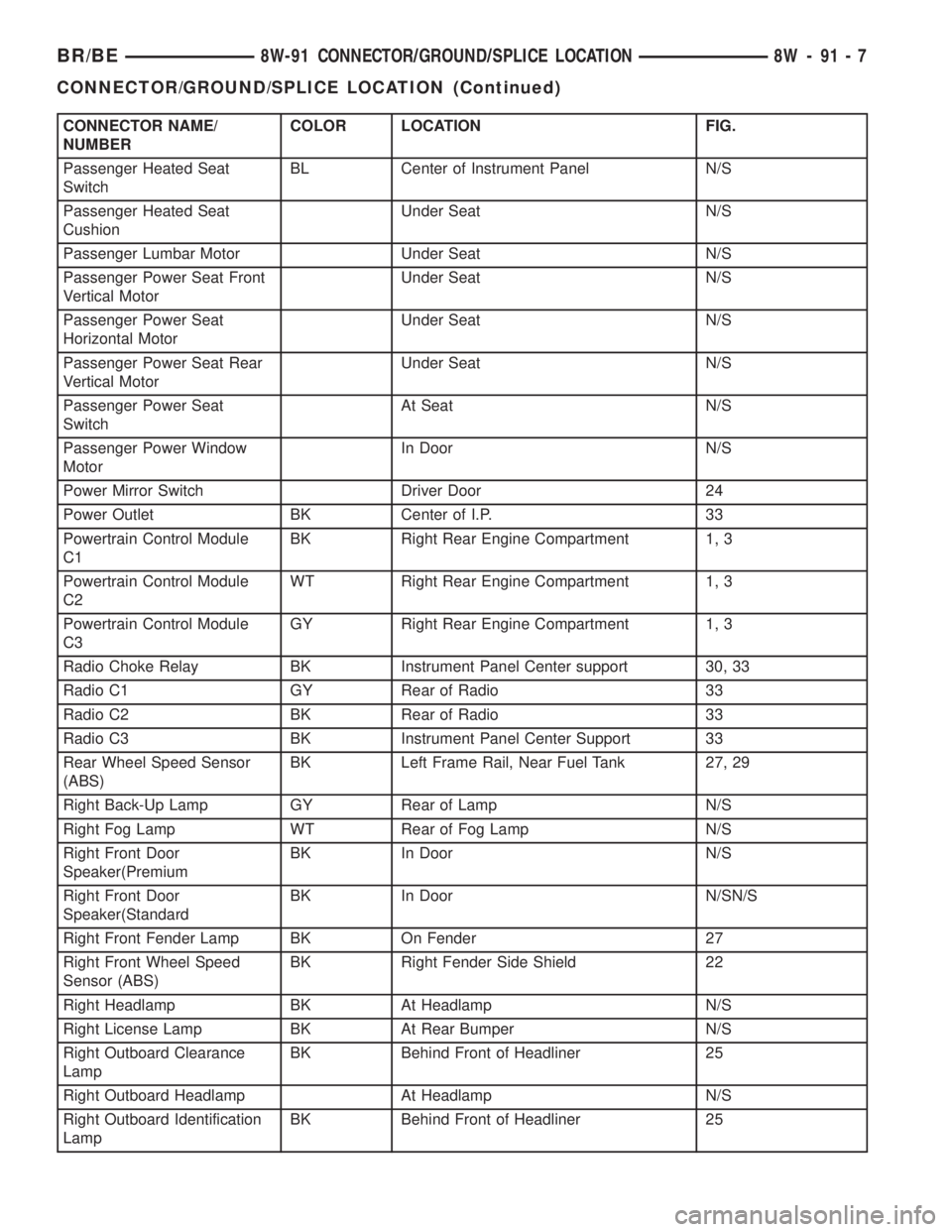
CONNECTOR NAME/
NUMBERCOLOR LOCATION FIG.
Passenger Heated Seat
SwitchBL Center of Instrument Panel N/S
Passenger Heated Seat
CushionUnder Seat N/S
Passenger Lumbar Motor Under Seat N/S
Passenger Power Seat Front
Vertical MotorUnder Seat N/S
Passenger Power Seat
Horizontal MotorUnder Seat N/S
Passenger Power Seat Rear
Vertical MotorUnder Seat N/S
Passenger Power Seat
SwitchAt Seat N/S
Passenger Power Window
MotorIn Door N/S
Power Mirror Switch Driver Door 24
Power Outlet BK Center of I.P. 33
Powertrain Control Module
C1BK Right Rear Engine Compartment 1, 3
Powertrain Control Module
C2WT Right Rear Engine Compartment 1, 3
Powertrain Control Module
C3GY Right Rear Engine Compartment 1, 3
Radio Choke Relay BK Instrument Panel Center support 30, 33
Radio C1 GY Rear of Radio 33
Radio C2 BK Rear of Radio 33
Radio C3 BK Instrument Panel Center Support 33
Rear Wheel Speed Sensor
(ABS)BK Left Frame Rail, Near Fuel Tank 27, 29
Right Back-Up Lamp GY Rear of Lamp N/S
Right Fog Lamp WT Rear of Fog Lamp N/S
Right Front Door
Speaker(PremiumBK In Door N/S
Right Front Door
Speaker(StandardBK In Door N/SN/S
Right Front Fender Lamp BK On Fender 27
Right Front Wheel Speed
Sensor (ABS)BK Right Fender Side Shield 22
Right Headlamp BK At Headlamp N/S
Right License Lamp BK At Rear Bumper N/S
Right Outboard Clearance
LampBK Behind Front of Headliner 25
Right Outboard Headlamp At Headlamp N/S
Right Outboard Identification
LampBK Behind Front of Headliner 25
BR/BE8W-91 CONNECTOR/GROUND/SPLICE LOCATION 8W - 91 - 7
CONNECTOR/GROUND/SPLICE LOCATION (Continued)
Page 1026 of 2255

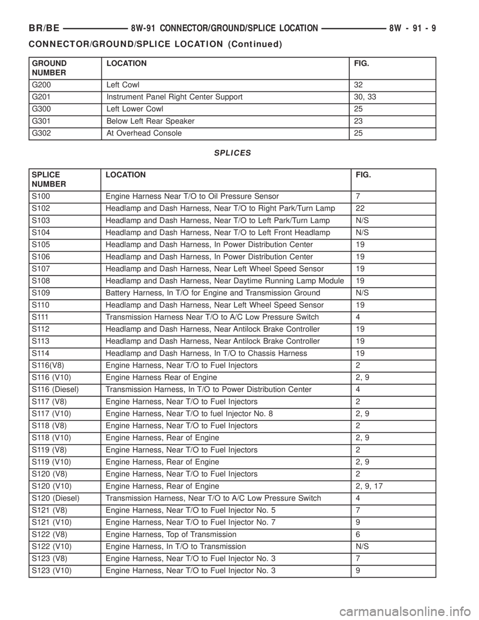
GROUND
NUMBERLOCATION FIG.
G200 Left Cowl 32
G201 Instrument Panel Right Center Support 30, 33
G300 Left Lower Cowl 25
G301 Below Left Rear Speaker 23
G302 At Overhead Console 25
SPLICES
SPLICE
NUMBERLOCATION FIG.
S100 Engine Harness Near T/O to Oil Pressure Sensor 7
S102 Headlamp and Dash Harness, Near T/O to Right Park/Turn Lamp 22
S103 Headlamp and Dash Harness, Near T/O to Left Park/Turn Lamp N/S
S104 Headlamp and Dash Harness, Near T/O to Left Front Headlamp N/S
S105 Headlamp and Dash Harness, In Power Distribution Center 19
S106 Headlamp and Dash Harness, In Power Distribution Center 19
S107 Headlamp and Dash Harness, Near Left Wheel Speed Sensor 19
S108 Headlamp and Dash Harness, Near Daytime Running Lamp Module 19
S109 Battery Harness, In T/O for Engine and Transmission Ground N/S
S110 Headlamp and Dash Harness, Near Left Wheel Speed Sensor 19
S111 Transmission Harness Near T/O to A/C Low Pressure Switch 4
S112 Headlamp and Dash Harness, Near Antilock Brake Controller 19
S113 Headlamp and Dash Harness, Near Antilock Brake Controller 19
S114 Headlamp and Dash Harness, In T/O to Chassis Harness 19
S116(V8) Engine Harness, Near T/O to Fuel Injectors 2
S116 (V10) Engine Harness Rear of Engine 2, 9
S116 (Diesel) Transmission Harness, In T/O to Power Distribution Center 4
S117 (V8) Engine Harness, Near T/O to Fuel Injectors 2
S117 (V10) Engine Harness, Near T/O to fuel Injector No. 8 2, 9
S118 (V8) Engine Harness, Near T/O to Fuel Injectors 2
S118 (V10) Engine Harness, Rear of Engine 2, 9
S119 (V8) Engine Harness, Near T/O to Fuel Injectors 2
S119 (V10) Engine Harness, Rear of Engine 2, 9
S120 (V8) Engine Harness, Near T/O to Fuel Injectors 2
S120 (V10) Engine Harness, Rear of Engine 2, 9, 17
S120 (Diesel) Transmission Harness, Near T/O to A/C Low Pressure Switch 4
S121 (V8) Engine Harness, Near T/O to Fuel Injector No. 5 7
S121 (V10) Engine Harness, Near T/O to Fuel Injector No. 7 9
S122 (V8) Engine Harness, Top of Transmission 6
S122 (V10) Engine Harness, In T/O to Transmission N/S
S123 (V8) Engine Harness, Near T/O to Fuel Injector No. 3 7
S123 (V10) Engine Harness, Near T/O to Fuel Injector No. 3 9
BR/BE8W-91 CONNECTOR/GROUND/SPLICE LOCATION 8W - 91 - 9
CONNECTOR/GROUND/SPLICE LOCATION (Continued)
Page 1028 of 2255

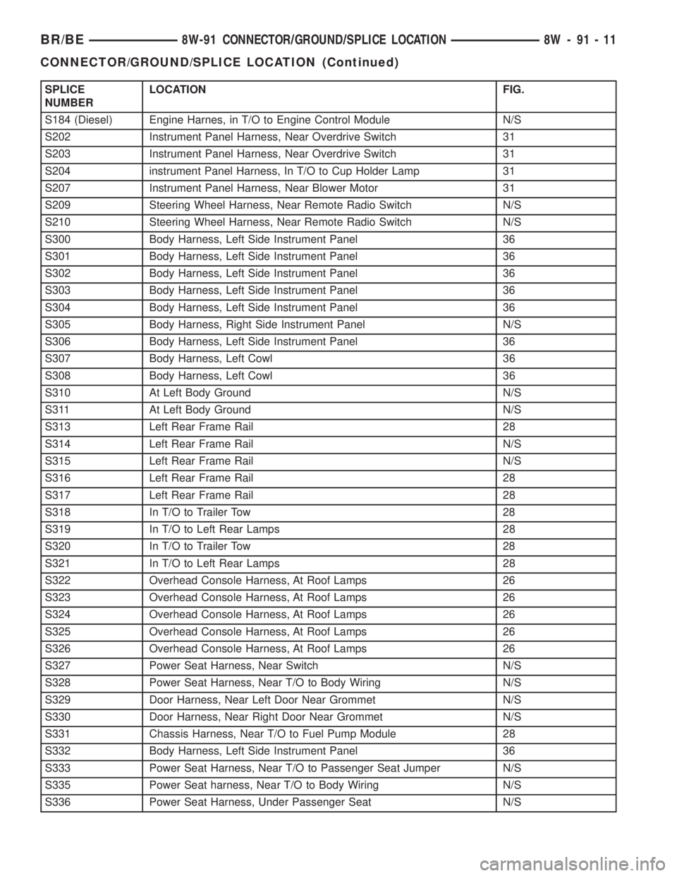
SPLICE
NUMBERLOCATION FIG.
S184 (Diesel) Engine Harnes, in T/O to Engine Control Module N/S
S202 Instrument Panel Harness, Near Overdrive Switch 31
S203 Instrument Panel Harness, Near Overdrive Switch 31
S204 instrument Panel Harness, In T/O to Cup Holder Lamp 31
S207 Instrument Panel Harness, Near Blower Motor 31
S209 Steering Wheel Harness, Near Remote Radio Switch N/S
S210 Steering Wheel Harness, Near Remote Radio Switch N/S
S300 Body Harness, Left Side Instrument Panel 36
S301 Body Harness, Left Side Instrument Panel 36
S302 Body Harness, Left Side Instrument Panel 36
S303 Body Harness, Left Side Instrument Panel 36
S304 Body Harness, Left Side Instrument Panel 36
S305 Body Harness, Right Side Instrument Panel N/S
S306 Body Harness, Left Side Instrument Panel 36
S307 Body Harness, Left Cowl 36
S308 Body Harness, Left Cowl 36
S310 At Left Body Ground N/S
S311 At Left Body Ground N/S
S313 Left Rear Frame Rail 28
S314 Left Rear Frame Rail N/S
S315 Left Rear Frame Rail N/S
S316 Left Rear Frame Rail 28
S317 Left Rear Frame Rail 28
S318 In T/O to Trailer Tow 28
S319 In T/O to Left Rear Lamps 28
S320 In T/O to Trailer Tow 28
S321 In T/O to Left Rear Lamps 28
S322 Overhead Console Harness, At Roof Lamps 26
S323 Overhead Console Harness, At Roof Lamps 26
S324 Overhead Console Harness, At Roof Lamps 26
S325 Overhead Console Harness, At Roof Lamps 26
S326 Overhead Console Harness, At Roof Lamps 26
S327 Power Seat Harness, Near Switch N/S
S328 Power Seat Harness, Near T/O to Body Wiring N/S
S329 Door Harness, Near Left Door Near Grommet N/S
S330 Door Harness, Near Right Door Near Grommet N/S
S331 Chassis Harness, Near T/O to Fuel Pump Module 28
S332 Body Harness, Left Side Instrument Panel 36
S333 Power Seat Harness, Near T/O to Passenger Seat Jumper N/S
S335 Power Seat harness, Near T/O to Body Wiring N/S
S336 Power Seat Harness, Under Passenger Seat N/S
BR/BE8W-91 CONNECTOR/GROUND/SPLICE LOCATION 8W - 91 - 11
CONNECTOR/GROUND/SPLICE LOCATION (Continued)
Page 1053 of 2255
Fig. 30 INSTRUMENT PANEL
8W - 91 - 36 8W-91 CONNECTOR/GROUND/SPLICE LOCATIONBR/BE
CONNECTOR/GROUND/SPLICE LOCATION (Continued)
Page 1054 of 2255
Fig. 31 INSTRUMENT PANEL
BR/BE8W-91 CONNECTOR/GROUND/SPLICE LOCATION 8W - 91 - 37
CONNECTOR/GROUND/SPLICE LOCATION (Continued)
Page 1056 of 2255
Fig. 33 INSTRUMENT PANEL
BR/BE8W-91 CONNECTOR/GROUND/SPLICE LOCATION 8W - 91 - 39
CONNECTOR/GROUND/SPLICE LOCATION (Continued)
Page 1057 of 2255
Fig. 34 INSTRUMENT PANEL
8W - 91 - 40 8W-91 CONNECTOR/GROUND/SPLICE LOCATIONBR/BE
CONNECTOR/GROUND/SPLICE LOCATION (Continued)
Page 1061 of 2255

tribution points for the electrical current required to
operate all of the many standard and optional facto-
ry-installed electrical and electronic powertrain,
chassis, safety, security, comfort and convenience sys-
tems. At the same time, the power distribution sys-
tem was designed to provide ready access to these
electrical distribution points for the vehicle techni-
cian to use when conducting diagnosis and repair of
faulty circuits. The power distribution system can
also prove useful for the sourcing of additional elec-
trical circuits that may be required to provide the
electrical current needed to operate many accessories
that the vehicle owner may choose to have installed
in the aftermarket.
SPECIAL TOOLS
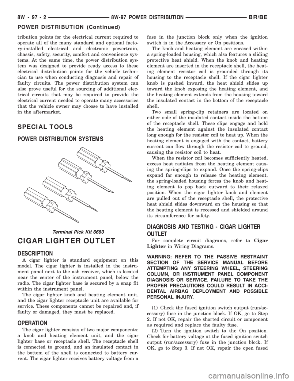
POWER DISTRIBUTION SYSTEMS
CIGAR LIGHTER OUTLET
DESCRIPTION
A cigar lighter is standard equipment on this
model. The cigar lighter is installed in the instru-
ment panel next to the ash receiver, which is located
near the center of the instrument panel, below the
radio. The cigar lighter base is secured by a snap fit
within the instrument panel.
The cigar lighter knob and heating element unit,
and the cigar lighter receptacle unit are available for
service. These components cannot be repaired and, if
faulty or damaged, they must be replaced.
OPERATION
The cigar lighter consists of two major components:
a knob and heating element unit, and the cigar
lighter base or receptacle shell. The receptacle shell
is connected to ground, and an insulated contact in
the bottom of the shell is connected to battery cur-
rent. The cigar lighter receives battery voltage from afuse in the junction block only when the ignition
switch is in the Accessory or On positions.
The knob and heating element are encased within
a spring-loaded housing, which also features a sliding
protective heat shield. When the knob and heating
element are inserted in the receptacle shell, the heat-
ing element resistor coil is grounded through its
housing to the receptacle shell. If the cigar lighter
knob is pushed inward, the heat shield slides up
toward the knob exposing the heating element, and
the heating element extends from the housing toward
the insulated contact in the bottom of the receptacle
shell.
Two small spring-clip retainers are located on
either side of the insulated contact inside the bottom
of the receptacle shell. These clips engage and hold
the heating element against the insulated contact
long enough for the resistor coil to heat up. When the
heating element is engaged with the contact, battery
current can flow through the resistor coil to ground,
causing the resistor coil to heat.
When the resistor coil becomes sufficiently heated,
excess heat radiates from the heating element caus-
ing the spring-clips to expand. Once the spring-clips
expand far enough to release the heating element,
the spring-loaded housing forces the knob and heat-
ing element to pop back outward to their relaxed
position. When the cigar lighter knob and element
are pulled out of the receptacle shell, the protective
heat shield slides downward on the housing so that
the heating element is recessed and shielded around
its circumference for safety.
DIAGNOSIS AND TESTING - CIGAR LIGHTER
OUTLET
For complete circuit diagrams, refer toCigar
Lighterin Wiring Diagrams.
WARNING: REFER TO THE PASSIVE RESTRAINT
SECTION OF THE SERVICE MANUAL BEFORE
ATTEMPTING ANY STEERING WHEEL, STEERING
COLUMN, OR INSTRUMENT PANEL COMPONENT
DIAGNOSIS OR SERVICE. FAILURE TO TAKE THE
PROPER PRECAUTIONS COULD RESULT IN ACCI-
DENTAL AIRBAG DEPLOYMENT AND POSSIBLE
PERSONAL INJURY.
(1) Check the fused ignition switch output (run/ac-
cessory) fuse in the junction block. If OK, go to Step
2. If not OK, repair the shorted circuit or component
as required and replace the faulty fuse.
(2) Turn the ignition switch to the On position.
Check for battery voltage at the fused ignition switch
output (run/accessory) fuse in the junction block. If
OK, go to Step 3. If not OK, repair the open fused
Terminal Pick Kit 6680
8W - 97 - 2 8W-97 POWER DISTRIBUTIONBR/BE
POWER DISTRIBUTION (Continued)