2002 DODGE RAM instrument panel
[x] Cancel search: instrument panelPage 1071 of 2255
(4) Press firmly on the cigar lighter or power out-
let receptacle base until the retaining bosses of the
mount are fully engaged in their receptacles.
(5) Install the cigar lighter knob and element into
the cigar lighter receptacle base, or the protective cap
into the power outlet receptacle base.
(6) Reconnect the battery negative cable.
HORN RELAY
DESCRIPTION
The horn relay is a International Standards Orga-
nization (ISO) micro-relay. The terminal designations
and functions are the same as a conventional ISO
relay. However, the micro-relay terminal orientation
(or footprint) is different, current capacity is lower,
and the relay case dimensions are smaller than those
of the conventional ISO relay.
The horn relay is a electromechanical device that
switches battery current to the horn when the horn
switch or when the high-line or premium Central
Timer Module (CTM) grounds the relay coil. See
Horn Relay in the Diagnosis and Testing section of
this group for more information.
The horn relay is located in the Power Distribution
Center (PDC), in the engine compartment. Refer to
the PDC label for relay identification and location.
If a problem is encountered with a continuously
sounding horn, it can usually be quickly resolved by
removing the horn relay from the PDC until further
diagnosis is completed.
The horn relay cannot be repaired and, if faulty or
damaged, it must be replaced.
DIAGNOSIS AND TESTING - HORN RELAY
The headlamp (or security) relay and the horn
relay are located in the Power Distribution Center
(PDC) in the engine compartment. Each of these
relays can be tested as described in the following pro-
cedure, however the circuits they are used in do vary.
To test the relay circuits, refer to the circuit descrip-
tions and diagrams in Wiring Diagrams.
WARNING: ON VEHICLES EQUIPPED WITH AIR-
BAGS, REFER TO THE RESTRAINTS SECTION OF
THE SERVICE MANUAL BEFORE ATTEMPTING ANY
STEERING WHEEL, STEERING COLUMN, OR
INSTRUMENT PANEL COMPONENT DIAGNOSIS OR
SERVICE. FAILURE TO TAKE THE PROPER PRE-
CAUTIONS COULD RESULT IN ACCIDENTAL AIR-
BAG DEPLOYMENT AND POSSIBLE PERSONAL
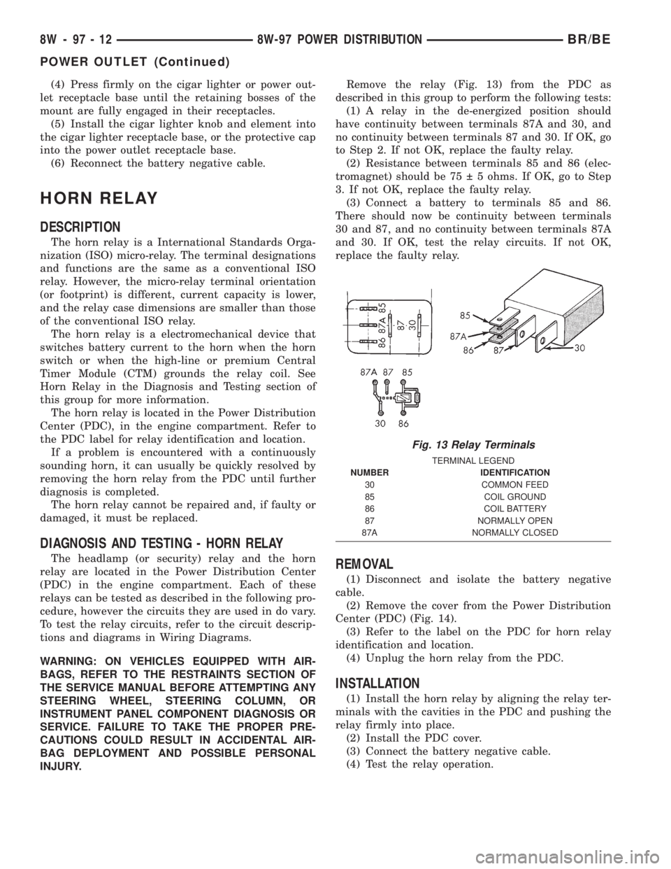
INJURY.Remove the relay (Fig. 13) from the PDC as
described in this group to perform the following tests:
(1) A relay in the de-energized position should
have continuity between terminals 87A and 30, and
no continuity between terminals 87 and 30. If OK, go
to Step 2. If not OK, replace the faulty relay.
(2) Resistance between terminals 85 and 86 (elec-
tromagnet) should be 75 5 ohms. If OK, go to Step
3. If not OK, replace the faulty relay.
(3) Connect a battery to terminals 85 and 86.
There should now be continuity between terminals
30 and 87, and no continuity between terminals 87A
and 30. If OK, test the relay circuits. If not OK,
replace the faulty relay.REMOVAL
(1) Disconnect and isolate the battery negative
cable.
(2) Remove the cover from the Power Distribution
Center (PDC) (Fig. 14).
(3) Refer to the label on the PDC for horn relay
identification and location.
(4) Unplug the horn relay from the PDC.
INSTALLATION
(1) Install the horn relay by aligning the relay ter-
minals with the cavities in the PDC and pushing the
relay firmly into place.
(2) Install the PDC cover.
(3) Connect the battery negative cable.
(4) Test the relay operation.
Fig. 13 Relay Terminals
TERMINAL LEGEND
NUMBER IDENTIFICATION
30 COMMON FEED
85 COIL GROUND
86 COIL BATTERY
87 NORMALLY OPEN
87A NORMALLY CLOSED
8W - 97 - 12 8W-97 POWER DISTRIBUTIONBR/BE
POWER OUTLET (Continued)
Page 1306 of 2255
INSTALLATION
(1) Install a new clamp over plastic fuel tube.
(2) Install filter/regulator to fuel tube. Rotate fil-
ter/regulator in fuel tube (line) (Fig. 8) until it is
pointed to drivers side of vehicle (Fig. 4) or (Fig. 5).
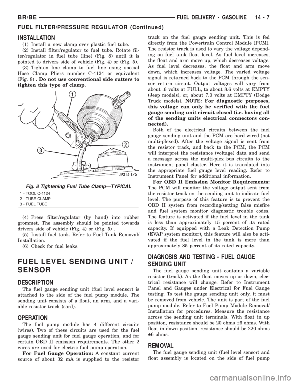
(3) Tighten line clamp to fuel line using special
Hose Clamp Pliers number C-4124 or equivalent
(Fig. 8) .Do not use conventional side cutters to
tighten this type of clamp.
(4) Press filter/regulator (by hand) into rubber
grommet. The assembly should be pointed towards
drivers side of vehicle (Fig. 4) or (Fig. 5) .
(5) Install fuel tank. Refer to Fuel Tank Removal/
Installation.
(6) Check for fuel leaks.
FUEL LEVEL SENDING UNIT /
SENSOR
DESCRIPTION
The fuel gauge sending unit (fuel level sensor) is
attached to the side of the fuel pump module. The
sending unit consists of a float, an arm, and a vari-
able resistor track (card).
OPERATION
The fuel pump module has 4 different circuits
(wires). Two of these circuits are used for the fuel
gauge sending unit for fuel gauge operation, and for
certain OBD II emission requirements. The other 2
wires are used for electric fuel pump operation.
For Fuel Gauge Operation:A constant current
source of about 32 mA is supplied to the resistortrack on the fuel gauge sending unit. This is fed
directly from the Powertrain Control Module (PCM).
The resistor track is used to vary the voltage depend-
ing on fuel tank float level. As fuel level increases,
the float and arm move up, which decreases voltage.
As fuel level decreases, the float and arm move
down, which increases voltage. The varied voltage
signal is returned back to the PCM through the sen-
sor return circuit. Output voltages will vary from
about .6 volts at FULL, to about 8.6 volts at EMPTY
(Jeep models), or, about 7.0 volts at EMPTY (Dodge
Truck models).NOTE: For diagnostic purposes,
this voltage can only be verified with the fuel
gauge sending unit circuit closed (i.e. having all
of the sending units electrical connectors con-
nected).
Both of the electrical circuits between the fuel
gauge sending unit and the PCM are hard-wired (not
multi-plexed). After the voltage signal is sent from
the resistor track, and back to the PCM, the PCM
will interpret the resistance (voltage) data and send
a message across the multi-plex bus circuits to the
instrument panel cluster. Here it is translated into
the appropriate fuel gauge level reading. Refer to
Instrument Panel for additional information.
For OBD II Emission Monitor Requirements:
The PCM will monitor the voltage output sent from
the resistor track on the sending unit to indicate fuel
level. The purpose of this feature is to prevent the
OBD II system from recording/setting false misfire
and fuel system monitor diagnostic trouble codes.
The feature is activated if the fuel level in the tank
is less than approximately 15 percent of its rated
capacity. If equipped with a Leak Detection Pump
(EVAP system monitor), this feature will also be acti-
vated if the fuel level in the tank is more than
approximately 85 percent of its rated capacity.
DIAGNOSIS AND TESTING - FUEL GAUGE
SENDING UNIT
The fuel gauge sending unit contains a variable
resistor (track). As the float moves up or down, elec-
trical resistance will change. Refer to Instrument
Panel and Gauges under Electrical for Fuel Gauge
testing. To test the gauge sending unit only, it must
be removed from vehicle. The unit is part of the fuel
pump module. Refer to Fuel Pump Module Removal/
Installation for procedures. Measure the resistance
across the sending unit terminals. With float in up
position, resistance should be 20 ohms 6 ohms. With
float in down position, resistance should be 220 ohms
6 ohms.
REMOVAL
The fuel gauge sending unit (fuel level sensor) and
float assembly is located on the side of fuel pump
Fig. 8 Tightening Fuel Tube ClampÐTYPICAL
1 - TOOL C-4124
2 - TUBE CLAMP
3 - FUEL TUBE
BR/BEFUEL DELIVERY - GASOLINE 14 - 7
FUEL FILTER/PRESSURE REGULATOR (Continued)
Page 1376 of 2255
FUEL INJECTION PUMP DATA
PLATE
SPECIFICATIONS
FUEL INJECTION PUMP DATA PLATE
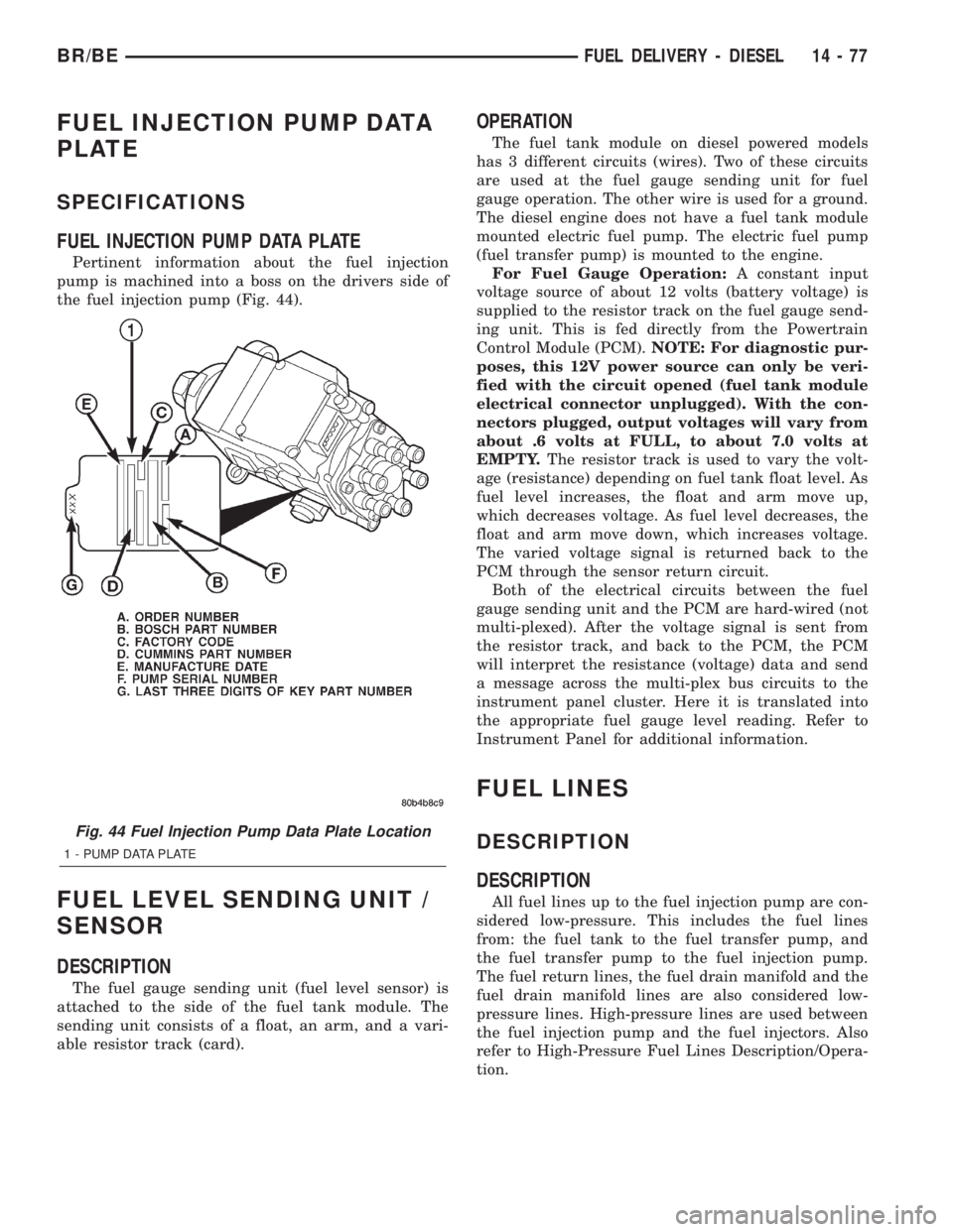
Pertinent information about the fuel injection
pump is machined into a boss on the drivers side of
the fuel injection pump (Fig. 44).
FUEL LEVEL SENDING UNIT /
SENSOR
DESCRIPTION
The fuel gauge sending unit (fuel level sensor) is
attached to the side of the fuel tank module. The
sending unit consists of a float, an arm, and a vari-
able resistor track (card).
OPERATION
The fuel tank module on diesel powered models
has 3 different circuits (wires). Two of these circuits
are used at the fuel gauge sending unit for fuel
gauge operation. The other wire is used for a ground.
The diesel engine does not have a fuel tank module
mounted electric fuel pump. The electric fuel pump
(fuel transfer pump) is mounted to the engine.
For Fuel Gauge Operation:A constant input
voltage source of about 12 volts (battery voltage) is
supplied to the resistor track on the fuel gauge send-
ing unit. This is fed directly from the Powertrain
Control Module (PCM).NOTE: For diagnostic pur-
poses, this 12V power source can only be veri-
fied with the circuit opened (fuel tank module
electrical connector unplugged). With the con-
nectors plugged, output voltages will vary from
about .6 volts at FULL, to about 7.0 volts at
EMPTY.The resistor track is used to vary the volt-
age (resistance) depending on fuel tank float level. As
fuel level increases, the float and arm move up,
which decreases voltage. As fuel level decreases, the
float and arm move down, which increases voltage.
The varied voltage signal is returned back to the
PCM through the sensor return circuit.
Both of the electrical circuits between the fuel
gauge sending unit and the PCM are hard-wired (not
multi-plexed). After the voltage signal is sent from
the resistor track, and back to the PCM, the PCM
will interpret the resistance (voltage) data and send
a message across the multi-plex bus circuits to the
instrument panel cluster. Here it is translated into
the appropriate fuel gauge level reading. Refer to
Instrument Panel for additional information.
FUEL LINES
DESCRIPTION
DESCRIPTION
All fuel lines up to the fuel injection pump are con-
sidered low-pressure. This includes the fuel lines
from: the fuel tank to the fuel transfer pump, and
the fuel transfer pump to the fuel injection pump.
The fuel return lines, the fuel drain manifold and the
fuel drain manifold lines are also considered low-
pressure lines. High-pressure lines are used between
the fuel injection pump and the fuel injectors. Also
refer to High-Pressure Fuel Lines Description/Opera-
tion.
Fig. 44 Fuel Injection Pump Data Plate Location
1 - PUMP DATA PLATE
BR/BEFUEL DELIVERY - DIESEL 14 - 77
Page 1390 of 2255
FUEL INJECTION - DIESEL
TABLE OF CONTENTS
page page
FUEL INJECTION - DIESEL
DESCRIPTION - DIESEL FUEL INJECTION
SYSTEM............................91
DIAGNOSIS AND TESTING - BOOST
PRESSURE..........................93
SPECIFICATIONS
TORQUE - DIESEL ENGINE.............94
ACCELERATOR PEDAL POSITION SENSOR
DESCRIPTION.........................95
OPERATION...........................95
REMOVAL.............................95
INSTALLATION.........................97
FUEL INJECTOR
DESCRIPTION.........................97
OPERATION...........................98
DIAGNOSIS AND TESTINGÐFUEL INJECTOR
TEST...............................99
REMOVAL............................101
INSTALLATION........................102
FUEL INJECTION PUMP RELAY
DESCRIPTION........................103
OPERATION..........................103
FUEL TEMPERATURE SENSOR
DESCRIPTION........................104
OPERATION..........................104
INTAKE AIR HEATER
DESCRIPTION........................104OPERATION..........................104
REMOVAL............................104
INSTALLATION........................105
INTAKE AIR HEATER RELAY
DESCRIPTION........................105
OPERATION..........................105
REMOVAL............................106
INSTALLATION........................106
INTAKE AIR TEMPERATURE SENSOR
DESCRIPTION - DIESEL.................106
OPERATION - DIESEL..................106
REMOVAL - DIESEL....................107
INSTALLATION - DIESEL................107
MAP SENSOR
DESCRIPTION - DIESEL.................108
OPERATION - DIESEL..................108
REMOVAL - DIESEL....................108
INSTALLATION........................108
PTO SWITCH
DESCRIPTION
OPERATION........................108
THROTTLE CONTROL CABLE
REMOVAL............................109
INSTALLATION........................110
FUEL INJECTION - DIESEL
DESCRIPTION - DIESEL FUEL INJECTION
SYSTEM
The Engine Control Module (ECM) and Fuel Injec-
tion Pump Control Module (FPCM) are used prima-
rily for fuel system control. The ECM is a separate
replaceable component, while the FPCM is internal
to the fuel injection pump and is a non-serviceable
part. The ECM and FPCM are interconnected (wired
together) for fuel injection control.The Powertrain Control Module (PCM) is used to
regulate or control the A/C, charging and speed con-
trol systems. It is also used to partially control cer-
tain electronic automatic transmission components.
The PCM also has control over certain instrument
panel components.
Refer to either Powertrain Control Module (PCM)
or Engine Control Module (ECM) for additional infor-
mation. Refer to (Fig. 1) for a partial list of fuel sys-
tem components.
BR/BEFUEL INJECTION - DIESEL 14 - 91
Page 1416 of 2255
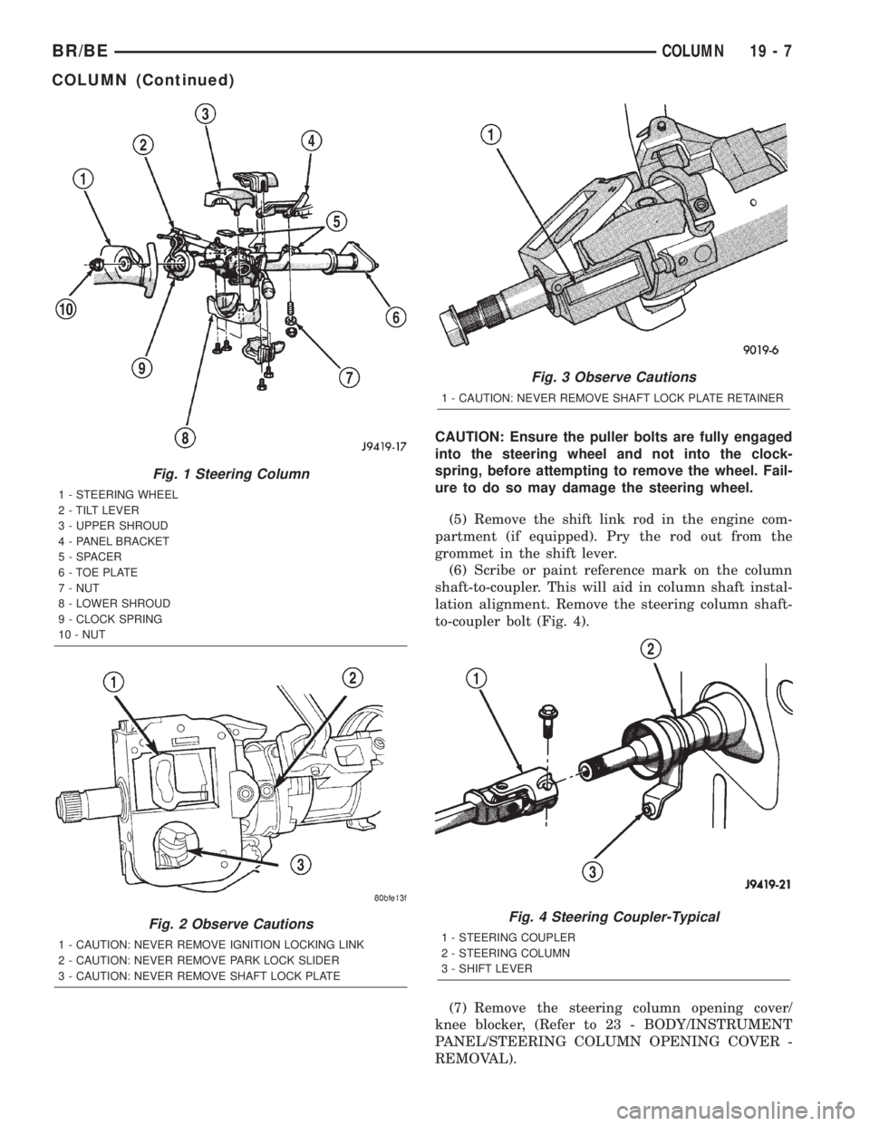
CAUTION: Ensure the puller bolts are fully engaged
into the steering wheel and not into the clock-
spring, before attempting to remove the wheel. Fail-
ure to do so may damage the steering wheel.
(5) Remove the shift link rod in the engine com-
partment (if equipped). Pry the rod out from the
grommet in the shift lever.
(6) Scribe or paint reference mark on the column
shaft-to-coupler. This will aid in column shaft instal-
lation alignment. Remove the steering column shaft-
to-coupler bolt (Fig. 4).
(7) Remove the steering column opening cover/
knee blocker, (Refer to 23 - BODY/INSTRUMENT
PANEL/STEERING COLUMN OPENING COVER -
REMOVAL).
Fig. 1 Steering Column
1 - STEERING WHEEL
2 - TILT LEVER
3 - UPPER SHROUD
4 - PANEL BRACKET
5 - SPACER
6 - TOE PLATE
7 - NUT
8 - LOWER SHROUD
9 - CLOCK SPRING
10 - NUT
Fig. 2 Observe Cautions
1 - CAUTION: NEVER REMOVE IGNITION LOCKING LINK
2 - CAUTION: NEVER REMOVE PARK LOCK SLIDER
3 - CAUTION: NEVER REMOVE SHAFT LOCK PLATE
Fig. 3 Observe Cautions
1 - CAUTION: NEVER REMOVE SHAFT LOCK PLATE RETAINER
Fig. 4 Steering Coupler-Typical
1 - STEERING COUPLER
2 - STEERING COLUMN
3 - SHIFT LEVER
BR/BECOLUMN 19 - 7
COLUMN (Continued)
Page 1418 of 2255
(3) Remove the shipping lock pin if necessary.
(4) Install the column through the floor pan.
(5) Position the column bracket breakaway cap-
sules on the mounting studs. Install, butloose
assemblethe two upper bracket nuts.
(6) With the front wheels in the straight-ahead
position. Align steering column shaft to the coupler.
Install anewpinch bolt and tighten to 49 N´m (36
ft. lbs.).
(7) Clip the wiring harness on the steering column.
Connect the multi- function switch wiring and
tighten with 7mm socket.
(8) Install the upper fixed shroud.
(9) Be sure both breakaway capsules are fully
seated in the slots in the column support bracket.
Pull the column rearward then tighten upper bracket
nuts to 12 N´m (105 in. lbs.).
(10) Tighten the toe plate to floor pan attaching
nuts to 22.5 N´m (200 in. lbs.).
(11) Install the wiring connections to the column.
Install the lower fixed shroud.
(12) Column shift vehicles, install the PRNDL
driver cable. Place shifter in Park position. If indica-tor needs adjusting, turn thumb screw on cable
retainer to adjust cable.
(13) Install the lock housing shrouds. Install the
tilt lever (if equipped).
(14) Install the knee blocker and steering column
opening cover, (Refer to 23 - BODY/INSTRUMENT
PANEL/STEERING COLUMN OPENING COVER -
INSTALLATION).
(15) Install steering wheel and tighten nut to 61
N´m (45 ft. lbs.), (Refer to 19 - STEERING/COL-
UMN/STEERING WHEEL - INSTALLATION).
(16) Install the airbag, (Refer to 8 - ELECTRICAL/
RESTRAINTS/DRIVER AIRBAG - INSTALLATION).
(17) Column shift vehicles, connect the shift link
rod to the transmission shift lever. Use multi-purpose
lubricant, or an equivalent product, to aid the instal-
lation.
(18) Install the battery ground (negative) cable.
(19) Verify operation of the automatic transmission
shift linkage and adjust as necessary, (Refer to 21 -
TRANSMISSION/TRANSAXLE/AUTOMATIC -
44RE/GEAR SHIFT CABLE - ADJUSTMENTS).
SPECIFICATIONS
TORQUE CHART
TORQUE SPECIFICATIONS
DESCRIPTION N´m Ft. Lbs. In. Lbs.
Steering Wheel
Nut61 45 Ð
Steering Coupler
Bolt49 36 Ð
Steering Column
Upper Bracket12 Ð 105
Steering Column
Toe Plate23 Ð 200
KEY-IN IGNITION SWITCH
DESCRIPTION
The key-in ignition switch is integral to the igni-
tion switch, which is mounted on the left side of the
steering column. It closes a path to ground for the
Central Timer Module (CTM) when the ignition key
is inserted in the ignition lock cylinder and the
driver door ajar switch is closed (driver door is open).
The key-in ignition switch opens the ground path
when the key is removed from the ignition lock cyl-
inder. The ground path is also opened when the
driver door ajar switch is open (driver door is closed).The key-in ignition switch cannot be repaired and,
if faulty or damaged, the entire ignition switch must
be replaced, (Refer to 19 - STEERING/COLUMN/IG-
NITION SWITCH - REMOVAL).
DIAGNOSIS AND TESTING - IGNITION SWITCH
AND KEY LOCK CYLINDER
ELECTRICAL DIAGNOSIS
For ignition switch electrical schematics, refer to
Ignition Switch in the appropriate section of Electri-
cal Wiring Diagrams.
BR/BECOLUMN 19 - 9
COLUMN (Continued)
Page 1423 of 2255
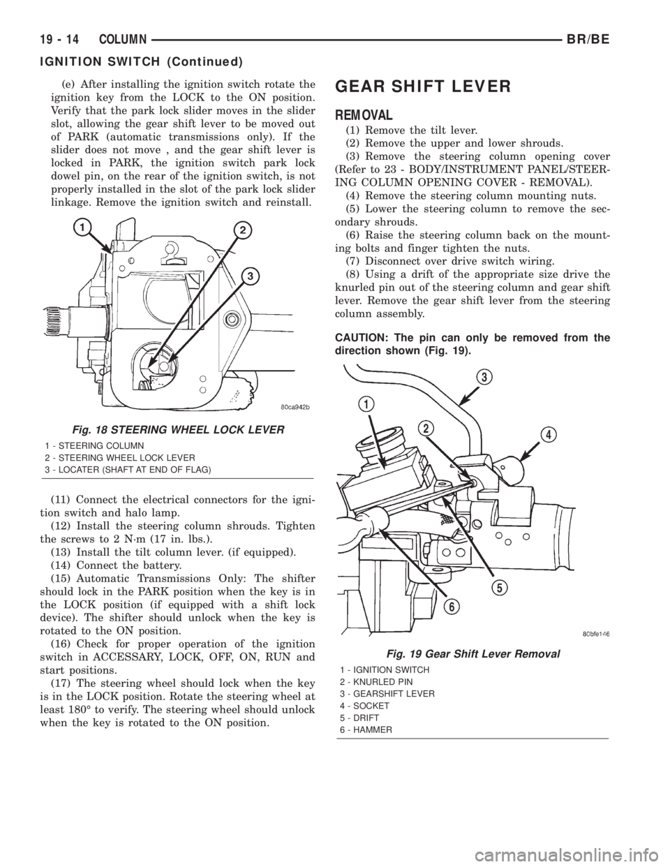
(e) After installing the ignition switch rotate the
ignition key from the LOCK to the ON position.
Verify that the park lock slider moves in the slider
slot, allowing the gear shift lever to be moved out
of PARK (automatic transmissions only). If the
slider does not move , and the gear shift lever is
locked in PARK, the ignition switch park lock
dowel pin, on the rear of the ignition switch, is not
properly installed in the slot of the park lock slider
linkage. Remove the ignition switch and reinstall.
(11) Connect the electrical connectors for the igni-
tion switch and halo lamp.
(12) Install the steering column shrouds. Tighten
the screws to 2 N´m (17 in. lbs.).
(13) Install the tilt column lever. (if equipped).
(14) Connect the battery.
(15) Automatic Transmissions Only: The shifter
should lock in the PARK position when the key is in
the LOCK position (if equipped with a shift lock
device). The shifter should unlock when the key is
rotated to the ON position.
(16) Check for proper operation of the ignition
switch in ACCESSARY, LOCK, OFF, ON, RUN and
start positions.
(17) The steering wheel should lock when the key
is in the LOCK position. Rotate the steering wheel at
least 180É to verify. The steering wheel should unlock
when the key is rotated to the ON position.GEAR SHIFT LEVER
REMOVAL
(1) Remove the tilt lever.
(2) Remove the upper and lower shrouds.
(3) Remove the steering column opening cover
(Refer to 23 - BODY/INSTRUMENT PANEL/STEER-
ING COLUMN OPENING COVER - REMOVAL).
(4) Remove the steering column mounting nuts.
(5) Lower the steering column to remove the sec-
ondary shrouds.
(6) Raise the steering column back on the mount-
ing bolts and finger tighten the nuts.
(7) Disconnect over drive switch wiring.
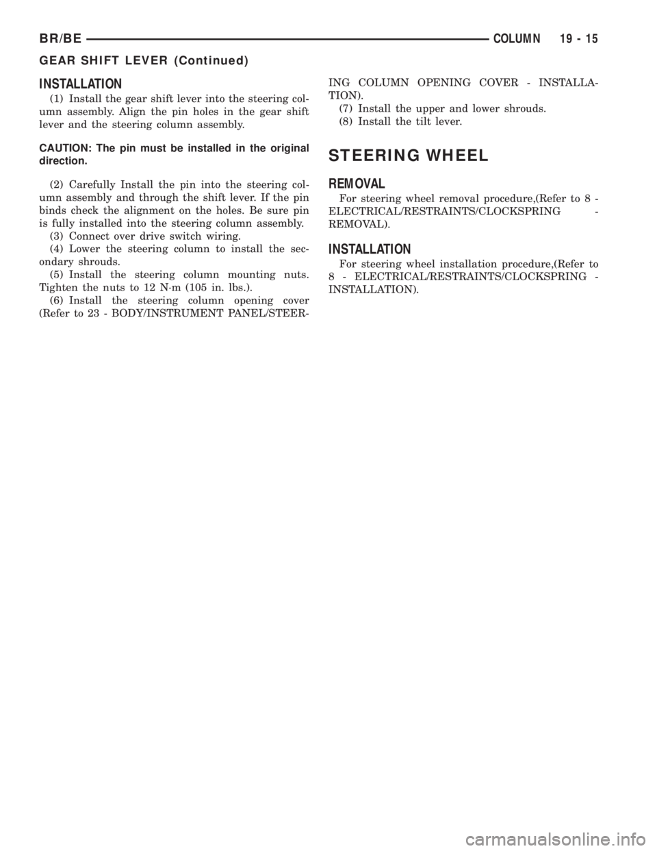
(8) Using a drift of the appropriate size drive the
knurled pin out of the steering column and gear shift
lever. Remove the gear shift lever from the steering
column assembly.
CAUTION: The pin can only be removed from the
direction shown (Fig. 19).
Fig. 18 STEERING WHEEL LOCK LEVER
1 - STEERING COLUMN
2 - STEERING WHEEL LOCK LEVER
3 - LOCATER (SHAFT AT END OF FLAG)
Fig. 19 Gear Shift Lever Removal
1 - IGNITION SWITCH
2 - KNURLED PIN
3 - GEARSHIFT LEVER
4 - SOCKET
5 - DRIFT
6 - HAMMER
19 - 14 COLUMNBR/BE
IGNITION SWITCH (Continued)
Page 1424 of 2255
INSTALLATION
(1) Install the gear shift lever into the steering col-
umn assembly. Align the pin holes in the gear shift
lever and the steering column assembly.
CAUTION: The pin must be installed in the original
direction.
(2) Carefully Install the pin into the steering col-
umn assembly and through the shift lever. If the pin
binds check the alignment on the holes. Be sure pin
is fully installed into the steering column assembly.
(3) Connect over drive switch wiring.
(4) Lower the steering column to install the sec-
ondary shrouds.
(5) Install the steering column mounting nuts.
Tighten the nuts to 12 N´m (105 in. lbs.).
(6) Install the steering column opening cover
(Refer to 23 - BODY/INSTRUMENT PANEL/STEER-ING COLUMN OPENING COVER - INSTALLA-
TION).
(7) Install the upper and lower shrouds.
(8) Install the tilt lever.
STEERING WHEEL
REMOVAL
For steering wheel removal procedure,(Refer to 8 -
ELECTRICAL/RESTRAINTS/CLOCKSPRING -
REMOVAL).
INSTALLATION
For steering wheel installation procedure,(Refer to
8 - ELECTRICAL/RESTRAINTS/CLOCKSPRING -
INSTALLATION).
BR/BECOLUMN 19 - 15
GEAR SHIFT LEVER (Continued)