2002 DODGE RAM instrument panel
[x] Cancel search: instrument panelPage 2144 of 2255
(1) The relay common feed terminal cavity (30) is
connected to fused battery feed directly from a fuse
in the Power Distribution Center (PDC), and should
be hot at all times. Check for battery voltage at the
PDC cavity for relay terminal 30. If OK, go to Step 2.
If not OK, repair the open circuit to the PDC fuse as
required.
(2) The relay normally closed terminal cavity (87A)
is not used for this application. Go to Step 3.
(3) The relay normally open terminal cavity (87) is
connected to the blower motor. When the relay is
energized, terminal 87 is connected to terminal 30
and provides full battery current to the blower motor
feed circuit. There should be continuity between the
PDC cavity for terminal 87 and the blower motor
relay output circuit cavity of the blower motor wire
harness connector at all times. If OK, go to Step 4. If
not OK, repair the open circuit to the blower motor
as required.
(4) The coil battery terminal cavity (86) is con-
nected to the ignition switch. When the ignition
switch is placed in the On position, fused ignition
switch output is directed from a fuse in the junction
block to the relay electromagnetic coil to energize the
relay. There should be battery voltage at the PDC
cavity for relay terminal 86 with the ignition switch
in the On position. If OK, go to Step 5. If not OK,
repair the open circuit to the junction block fuse as
required.
(5) The coil ground terminal cavity (85) is con-
nected to ground. This terminal supplies the ground
for the relay electromagnetic coil. There should be
continuity between the PDC cavity for relay terminal
85 and a good ground at all times. If not OK, repair
the open circuit as required.
REMOVAL
(1) Disconnect and isolate the battery negative
cable.
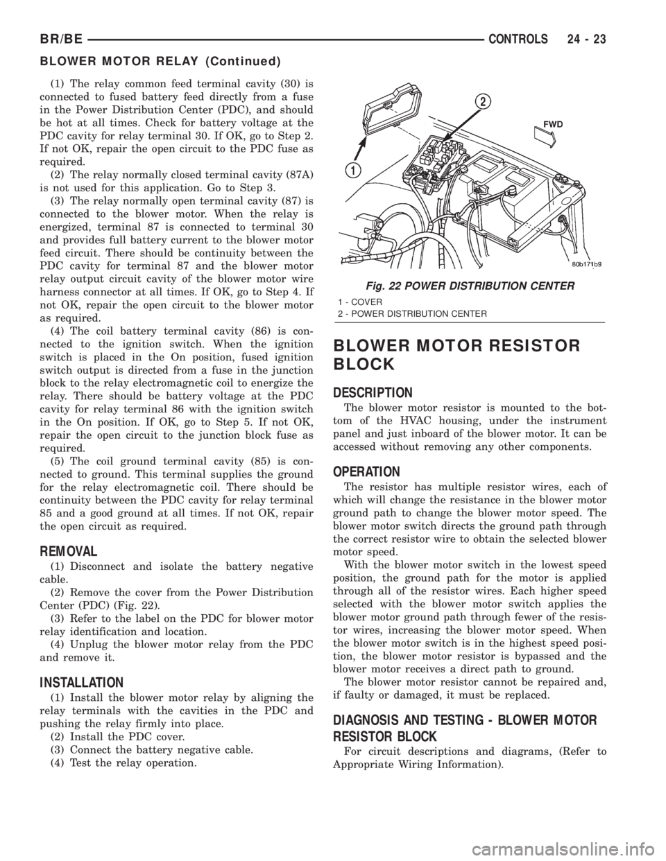
(2) Remove the cover from the Power Distribution
Center (PDC) (Fig. 22).
(3) Refer to the label on the PDC for blower motor
relay identification and location.
(4) Unplug the blower motor relay from the PDC
and remove it.
INSTALLATION
(1) Install the blower motor relay by aligning the
relay terminals with the cavities in the PDC and
pushing the relay firmly into place.
(2) Install the PDC cover.
(3) Connect the battery negative cable.
(4) Test the relay operation.
BLOWER MOTOR RESISTOR
BLOCK
DESCRIPTION
The blower motor resistor is mounted to the bot-
tom of the HVAC housing, under the instrument
panel and just inboard of the blower motor. It can be
accessed without removing any other components.
OPERATION
The resistor has multiple resistor wires, each of
which will change the resistance in the blower motor
ground path to change the blower motor speed. The
blower motor switch directs the ground path through
the correct resistor wire to obtain the selected blower
motor speed.
With the blower motor switch in the lowest speed
position, the ground path for the motor is applied
through all of the resistor wires. Each higher speed
selected with the blower motor switch applies the
blower motor ground path through fewer of the resis-
tor wires, increasing the blower motor speed. When
the blower motor switch is in the highest speed posi-
tion, the blower motor resistor is bypassed and the
blower motor receives a direct path to ground.
The blower motor resistor cannot be repaired and,
if faulty or damaged, it must be replaced.
DIAGNOSIS AND TESTING - BLOWER MOTOR
RESISTOR BLOCK
For circuit descriptions and diagrams, (Refer to
Appropriate Wiring Information).
Fig. 22 POWER DISTRIBUTION CENTER
1 - COVER
2 - POWER DISTRIBUTION CENTER
BR/BECONTROLS 24 - 23
BLOWER MOTOR RELAY (Continued)
Page 2145 of 2255
WARNING: ON VEHICLES EQUIPPED WITH AIR-
BAGS, DISABLE THE AIRBAG SYSTEM BEFORE
ATTEMPTING ANY STEERING WHEEL, STEERING
COLUMN, OR INSTRUMENT PANEL COMPONENT
DIAGNOSIS OR SERVICE. DISCONNECT AND ISO-
LATE THE BATTERY NEGATIVE (GROUND) CABLE,
THEN WAIT TWO MINUTES FOR THE AIRBAG SYS-
TEM CAPACITOR TO DISCHARGE BEFORE PER-
FORMING FURTHER DIAGNOSIS OR SERVICE. THIS
IS THE ONLY SURE WAY TO DISABLE THE AIRBAG
SYSTEM. FAILURE TO TAKE THE PROPER PRE-
CAUTIONS COULD RESULT IN AN ACCIDENTAL
AIRBAG DEPLOYMENT AND POSSIBLE PERSONAL
INJURY.
(1) Disconnect and isolate the battery negative
cable.
(2) Unplug the wire harness connector from the
blower motor resistor.
(3) Check for continuity between each of the
blower motor switch input terminals of the resistor
and the resistor output terminal. In each case there
should be continuity. If OK, repair the wire harness
circuits between the blower motor switch and the
blower motor resistor or blower motor as required. If
not OK, replace the faulty blower motor resistor.
REMOVAL
WARNING: ON VEHICLES EQUIPPED WITH AIR-
BAGS, DISABLE THE AIRBAG SYSTEM BEFORE
ATTEMPTING ANY STEERING WHEEL, STEERING
COLUMN, OR INSTRUMENT PANEL COMPONENT
DIAGNOSIS OR SERVICE. DISCONNECT AND ISO-
LATE THE BATTERY NEGATIVE (GROUND) CABLE,
THEN WAIT TWO MINUTES FOR THE AIRBAG SYS-
TEM CAPACITOR TO DISCHARGE BEFORE PER-
FORMING FURTHER DIAGNOSIS OR SERVICE. THIS
IS THE ONLY SURE WAY TO DISABLE THE AIRBAG
SYSTEM. FAILURE TO TAKE THE PROPER PRE-
CAUTIONS COULD RESULT IN AN ACCIDENTAL
AIRBAG DEPLOYMENT AND POSSIBLE PERSONAL
INJURY.
(1) Disconnect and isolate the battery negative
cable.
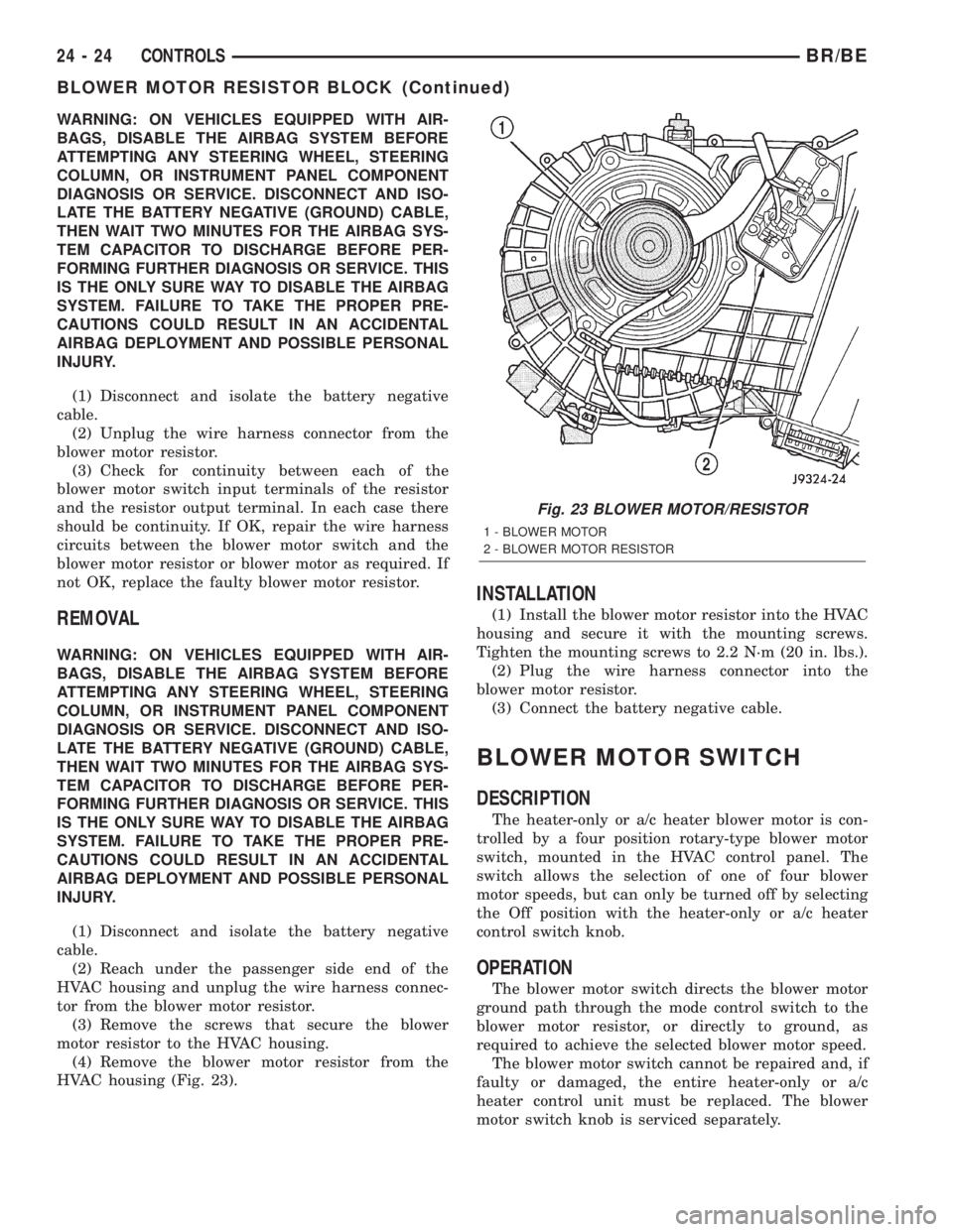
(2) Reach under the passenger side end of the
HVAC housing and unplug the wire harness connec-
tor from the blower motor resistor.
(3) Remove the screws that secure the blower
motor resistor to the HVAC housing.
(4) Remove the blower motor resistor from the
HVAC housing (Fig. 23).
INSTALLATION
(1) Install the blower motor resistor into the HVAC
housing and secure it with the mounting screws.
Tighten the mounting screws to 2.2 N´m (20 in. lbs.).
(2) Plug the wire harness connector into the
blower motor resistor.
(3) Connect the battery negative cable.
BLOWER MOTOR SWITCH
DESCRIPTION
The heater-only or a/c heater blower motor is con-
trolled by a four position rotary-type blower motor
switch, mounted in the HVAC control panel. The
switch allows the selection of one of four blower
motor speeds, but can only be turned off by selecting
the Off position with the heater-only or a/c heater
control switch knob.
OPERATION
The blower motor switch directs the blower motor
ground path through the mode control switch to the
blower motor resistor, or directly to ground, as
required to achieve the selected blower motor speed.
The blower motor switch cannot be repaired and, if
faulty or damaged, the entire heater-only or a/c
heater control unit must be replaced. The blower
motor switch knob is serviced separately.
Fig. 23 BLOWER MOTOR/RESISTOR
1 - BLOWER MOTOR
2 - BLOWER MOTOR RESISTOR
24 - 24 CONTROLSBR/BE
BLOWER MOTOR RESISTOR BLOCK (Continued)
Page 2146 of 2255
DIAGNOSIS AND TESTING - BLOWER MOTOR
SWITCH
For circuit descriptions and diagrams, (Refer to
Appropriate Wiring Information).
WARNING: ON VEHICLES EQUIPPED WITH AIR-
BAGS, DISABLE THE AIRBAG SYSTEM BEFORE
ATTEMPTING ANY STEERING WHEEL, STEERING
COLUMN, OR INSTRUMENT PANEL COMPONENT
DIAGNOSIS OR SERVICE. DISCONNECT AND ISO-
LATE THE BATTERY NEGATIVE (GROUND) CABLE,
THEN WAIT TWO MINUTES FOR THE AIRBAG SYS-
TEM CAPACITOR TO DISCHARGE BEFORE PER-
FORMING FURTHER DIAGNOSIS OR SERVICE. THIS
IS THE ONLY SURE WAY TO DISABLE THE AIRBAG
SYSTEM. FAILURE TO TAKE THE PROPER PRE-
CAUTIONS COULD RESULT IN AN ACCIDENTAL
AIRBAG DEPLOYMENT AND POSSIBLE PERSONAL
INJURY.
(1) Check for battery voltage at the fuse in the
Power Distribution Center (PDC). If OK, go to Step
2. If not OK, repair the shorted circuit or component
as required and replace the faulty fuse.
(2) Turn the ignition switch to the Off position.
Disconnect and isolate the battery negative cable.
Remove the a/c heater control from the instrument
panel. (Refer to 24 - HEATING & AIR CONDITION-
ING/CONTROLS/A/C HEATER CONTROL -
REMOVAL) Check for continuity between the ground
circuit cavity of the a/c heater control wire harness
connector and a good ground. There should be conti-
nuity. If OK, go to Step 3. If not OK, repair the open
circuit to ground as required.
(3) With the a/c heater control wire harness con-
nector unplugged, place the a/c heater mode control
switch knob in any position except the Off position.
Check for continuity between the ground circuit ter-
minal and each of the blower motor driver circuit ter-
minals of the a/c heater control as you move the
blower motor switch knob to each of the four speed
positions. There should be continuity at each driver
circuit terminal in only one blower motor switch
speed position. If OK, test and repair the blower
driver circuits between the a/c heater control connec-
tor and the blower motor resistor as required. If not
OK, replace the faulty a/c heater control unit.
REMOVAL
The blower motor switch cannot be repaired and, if
faulty or damaged, the entire heater-only or a/c
heater control unit must be replaced. (Refer to 24 -
HEATING & AIR CONDITIONING/CONTROLS/A/C
HEATER CONTROL - REMOVAL) The blower motor
switch knob is serviced separately.
BLEND DOOR ACTUATOR
REMOVAL
WARNING: ON VEHICLES EQUIPPED WITH AIR-
BAGS, DISABLE THE AIRBAG SYSTEM BEFORE
ATTEMPTING ANY STEERING WHEEL, STEERING
COLUMN, OR INSTRUMENT PANEL COMPONENT
DIAGNOSIS OR SERVICE. DISCONNECT AND ISO-
LATE THE BATTERY NEGATIVE (GROUND) CABLE,
THEN WAIT TWO MINUTES FOR THE AIRBAG SYS-
TEM CAPACITOR TO DISCHARGE BEFORE PER-
FORMING FURTHER DIAGNOSIS OR SERVICE. THIS
IS THE ONLY SURE WAY TO DISABLE THE AIRBAG
SYSTEM. FAILURE TO TAKE THE PROPER PRE-
CAUTIONS COULD RESULT IN AN ACCIDENTAL
AIRBAG DEPLOYMENT AND POSSIBLE PERSONAL
INJURY.
(1) Turn the ignition switch to the run position.
(2) Locate the temperature control knob in the mid
(12 o'clock) position.
(3) Turn the ignition switch to the off position.
(4) Disconnect and isolate the battery negative
cable.
(5) Remove the instrument panel from the vehi-
cle(Refer to 23 - BODY/INSTRUMENT PANEL/IN-
STRUMENT PANEL ASSEMBLY - REMOVAL).
(6) Remove the HVAC housing from the vehicle.
(Refer to 24 - HEATING & AIR CONDITIONING/
DISTRIBUTION/HVAC HOUSING - REMOVAL)
(7) Unplug the wire harness connector from the
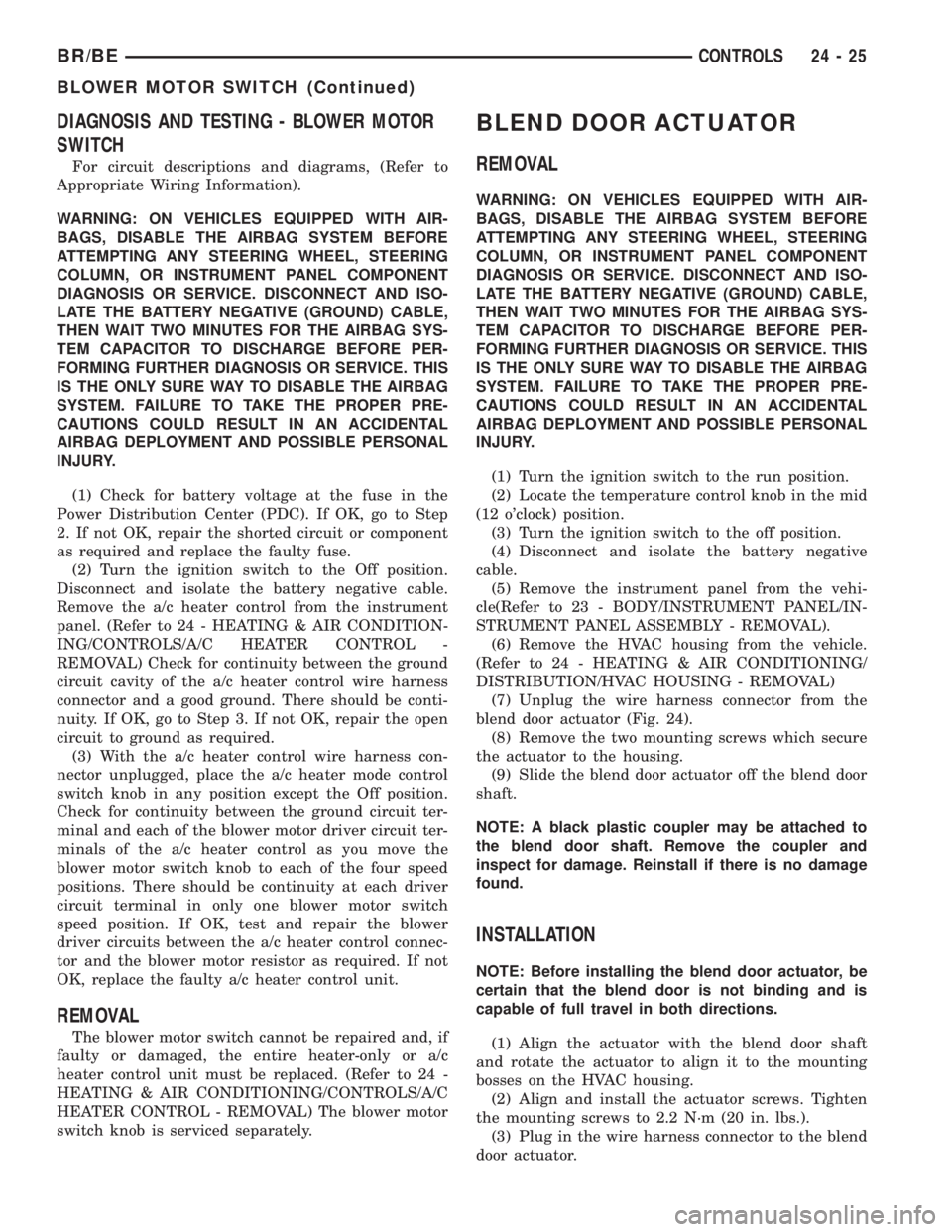
blend door actuator (Fig. 24).
(8) Remove the two mounting screws which secure
the actuator to the housing.
(9) Slide the blend door actuator off the blend door
shaft.
NOTE: A black plastic coupler may be attached to
the blend door shaft. Remove the coupler and
inspect for damage. Reinstall if there is no damage
found.
INSTALLATION
NOTE: Before installing the blend door actuator, be
certain that the blend door is not binding and is
capable of full travel in both directions.
(1) Align the actuator with the blend door shaft
and rotate the actuator to align it to the mounting
bosses on the HVAC housing.
(2) Align and install the actuator screws. Tighten
the mounting screws to 2.2 N´m (20 in. lbs.).
(3) Plug in the wire harness connector to the blend
door actuator.
BR/BECONTROLS 24 - 25
BLOWER MOTOR SWITCH (Continued)
Page 2147 of 2255
(4) Install the HVAC housing in the vehicle. (Refer
to 24 - HEATING & AIR CONDITIONING/DISTRI-
BUTION/HVAC HOUSING - INSTALLATION)
(5) Install the instrument panel in the vehicle(Re-
fer to 23 - BODY/INSTRUMENT PANEL/INSTRU-
MENT PANEL ASSEMBLY - INSTALLATION).
(6) Make sure the Temperature Control Knob is in
the mid (12 o'clock) position to allow the actuator to
automatically position itself in the mid position and
come to a complete stop when powered up.
(7) Connect the battery negative cable.
MODE DOOR ACTUATOR
REMOVAL - HEAT/DEFROST DOOR ACTUATOR
WARNING: ON VEHICLES EQUIPPED WITH AIR-
BAGS, DISABLE THE AIRBAG SYSTEM BEFORE
ATTEMPTING ANY STEERING WHEEL, STEERING
COLUMN, OR INSTRUMENT PANEL COMPONENT
DIAGNOSIS OR SERVICE. DISCONNECT AND ISO-
LATE THE BATTERY NEGATIVE (GROUND) CABLE,
THEN WAIT TWO MINUTES FOR THE AIRBAG SYS-
TEM CAPACITOR TO DISCHARGE BEFORE PER-
FORMING FURTHER DIAGNOSIS OR SERVICE. THIS
IS THE ONLY SURE WAY TO DISABLE THE AIRBAG
SYSTEM. FAILURE TO TAKE THE PROPER PRE-
CAUTIONS COULD RESULT IN AN ACCIDENTALAIRBAG DEPLOYMENT AND POSSIBLE PERSONAL
INJURY.
(1) Disconnect and isolate the battery negative
cable.
(2) Remove the HVAC housing from the vehicle
and place it on a work bench. (Refer to 24 - HEAT-
ING & AIR CONDITIONING/DISTRIBUTION/HVAC
HOUSING - REMOVAL)
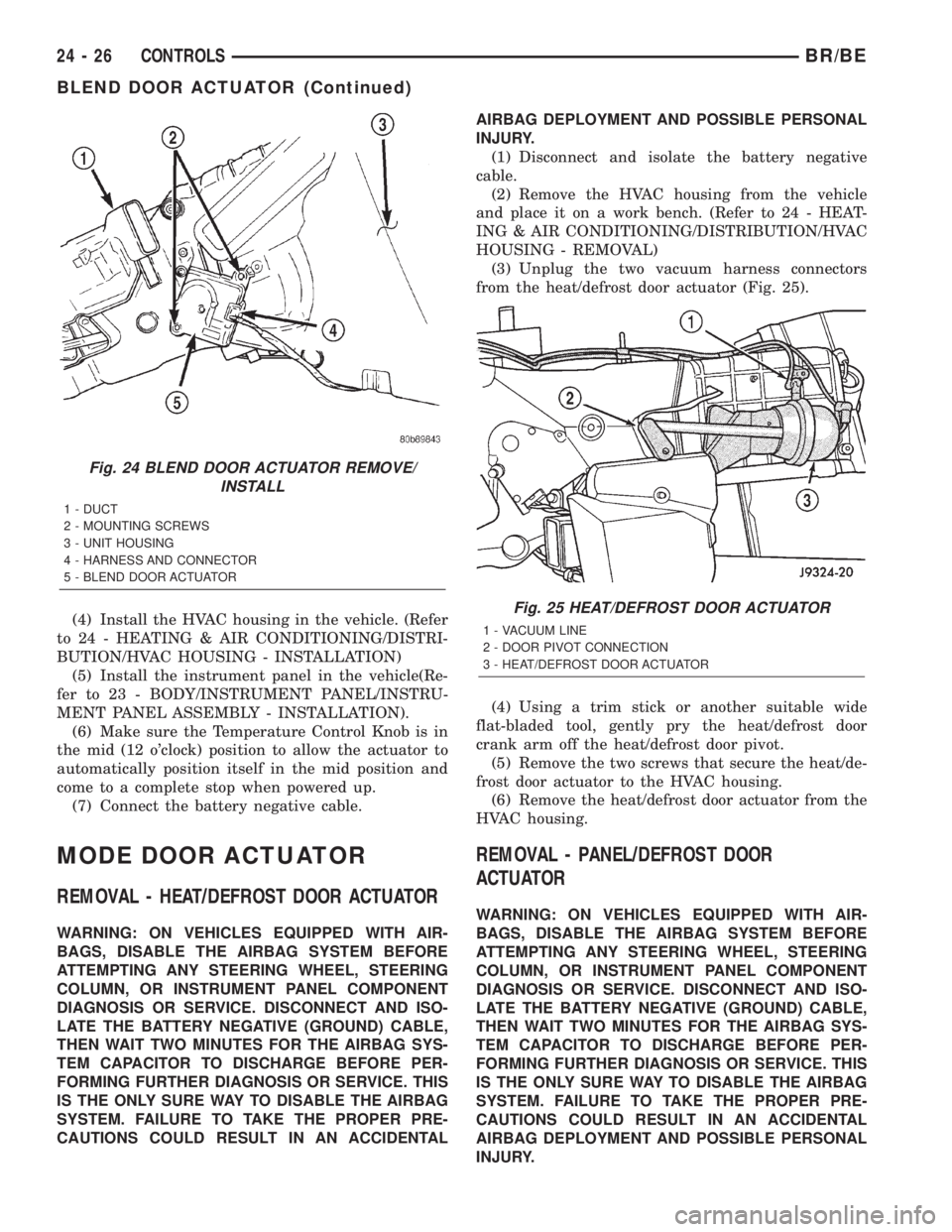
(3) Unplug the two vacuum harness connectors
from the heat/defrost door actuator (Fig. 25).
(4) Using a trim stick or another suitable wide
flat-bladed tool, gently pry the heat/defrost door
crank arm off the heat/defrost door pivot.
(5) Remove the two screws that secure the heat/de-
frost door actuator to the HVAC housing.
(6) Remove the heat/defrost door actuator from the
HVAC housing.
REMOVAL - PANEL/DEFROST DOOR
ACTUATOR
WARNING: ON VEHICLES EQUIPPED WITH AIR-
BAGS, DISABLE THE AIRBAG SYSTEM BEFORE
ATTEMPTING ANY STEERING WHEEL, STEERING
COLUMN, OR INSTRUMENT PANEL COMPONENT
DIAGNOSIS OR SERVICE. DISCONNECT AND ISO-
LATE THE BATTERY NEGATIVE (GROUND) CABLE,
THEN WAIT TWO MINUTES FOR THE AIRBAG SYS-
TEM CAPACITOR TO DISCHARGE BEFORE PER-
FORMING FURTHER DIAGNOSIS OR SERVICE. THIS
IS THE ONLY SURE WAY TO DISABLE THE AIRBAG
SYSTEM. FAILURE TO TAKE THE PROPER PRE-
CAUTIONS COULD RESULT IN AN ACCIDENTAL
AIRBAG DEPLOYMENT AND POSSIBLE PERSONAL
INJURY.
Fig. 24 BLEND DOOR ACTUATOR REMOVE/
INSTALL
1 - DUCT
2 - MOUNTING SCREWS
3 - UNIT HOUSING
4 - HARNESS AND CONNECTOR
5 - BLEND DOOR ACTUATOR
Fig. 25 HEAT/DEFROST DOOR ACTUATOR
1 - VACUUM LINE
2 - DOOR PIVOT CONNECTION
3 - HEAT/DEFROST DOOR ACTUATOR
24 - 26 CONTROLSBR/BE
BLEND DOOR ACTUATOR (Continued)
Page 2148 of 2255

(1) Disconnect and isolate the battery negative
cable.
(2) Remove the instrument panel assembly from
the vehicle(Refer to 23 - BODY/INSTRUMENT PAN-
EL/INSTRUMENT PANEL ASSEMBLY - REMOV-
AL).
(3) Unplug the vacuum harness connector from the
panel/defrost door actuator (Fig. 26).
(4) Using a trim stick or another suitable wide
flat-bladed tool, gently pry the panel/defrost door
crank arm off the panel/defrost door pivot.
(5) Remove the two screws that secure the panel/
defrost door actuator to the HVAC housing.
(6) Remove the panel/defrost door actuator from
the HVAC housing.
INSTALLATION - HEAT/DEFROST DOOR
ACTUATOR
NOTE: Before installing the heat/defrost door actua-
tor, be certain that the heat/defrost door is not bind-
ing.
(1) Install the heat/defrost door actuator from the
HVAC housing. Tighten the actuator mounting
screws to 2.2 N´m (20 in. lbs.).
(2) Carefully snap the heat/defrost door crank arm
on the heat/defrost door pivot.(3) Plug in the two vacuum harness connectors to
the heat/defrost door actuator.
(4) Install the HVAC housing in the vehicle. (Refer
to 24 - HEATING & AIR CONDITIONING/DISTRI-
BUTION/HVAC HOUSING - INSTALLATION)
(5) Connect the battery negative cable.
INSTALLATION - PANEL/DEFROST DOOR
ACTUATOR
NOTE: Before installing the panel/defrost door
actuator, be certain that the panel/defrost door is
not binding.
(1) Install the panel/defrost door actuator on the
HVAC housing. Tighten the mounting screws to 2.2
N´m (20 in. lbs.).
(2) Carefully snap the panel/defrost door crank
arm on the panel/defrost door pivot.
(3) Plug the vacuum harness connector to the pan-
el/defrost door actuator.
(4) Install the instrument panel assembly in the
vehicle(Refer to 23 - BODY/INSTRUMENT PANEL/
INSTRUMENT PANEL ASSEMBLY - INSTALLA-
TION).
(5) Connect the battery negative cable.
RECIRCULATION DOOR
ACTUATOR
REMOVAL
WARNING: ON VEHICLES EQUIPPED WITH AIR-
BAGS, DISABLE THE AIRBAG SYSTEM BEFORE
ATTEMPTING ANY STEERING WHEEL, STEERING
COLUMN, OR INSTRUMENT PANEL COMPONENT
DIAGNOSIS OR SERVICE. DISCONNECT AND ISO-
LATE THE BATTERY NEGATIVE (GROUND) CABLE,
THEN WAIT TWO MINUTES FOR THE AIRBAG SYS-
TEM CAPACITOR TO DISCHARGE BEFORE PER-
FORMING FURTHER DIAGNOSIS OR SERVICE. THIS
IS THE ONLY SURE WAY TO DISABLE THE AIRBAG
SYSTEM. FAILURE TO TAKE THE PROPER PRE-
CAUTIONS COULD RESULT IN AN ACCIDENTAL
AIRBAG DEPLOYMENT AND POSSIBLE PERSONAL
INJURY.
(1) Disconnect and isolate the battery negative
cable.
(2) Remove the glove box from the instrument pan-
el(Refer to 23 - BODY/INSTRUMENT PANEL/IN-
STRUMENT PANEL ASSEMBLY - REMOVAL).
Fig. 26 PANEL/DEFROST DOOR ACTUATOR
1 - VACUUM LINE
2 - PANEL/DEFROST ACTUATOR
3 - SHAFT RETAINER
BR/BECONTROLS 24 - 27
MODE DOOR ACTUATOR (Continued)
Page 2149 of 2255
(3) Reach through the glove box opening to access
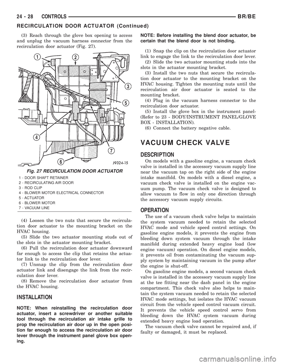
and unplug the vacuum harness connector from the
recirculation door actuator (Fig. 27).
(4) Loosen the two nuts that secure the recircula-
tion door actuator to the mounting bracket on the
HVAC housing.
(5) Slide the two actuator mounting studs out of
the slots in the actuator mounting bracket.
(6) Pull the recirculation door actuator downward
far enough to access the clip that retains the actua-
tor link to the recirculation door lever.
(7) Unsnap the clip from the recirculation door
actuator link and disengage the link from the recir-
culation door lever.
(8) Remove the recirculation door actuator from
the HVAC housing.
INSTALLATION
NOTE: When reinstalling the recirculation door
actuator, insert a screwdriver or another suitable
tool through the recirculation air intake grille to
prop the recirculation air door up in the open posi-
tion far enough to access the recirculation air door
lever through the instrument panel glove box open-
ing.NOTE: Before installing the blend door actuator, be
certain that the blend door is not binding.
(1) Snap the clip on the recirculation door actuator
link to engage the link to the recirculation door lever.
(2) Slide the two actuator mounting studs into the
slots in the actuator mounting bracket.
(3) Install the two nuts that secure the recircula-
tion door actuator to the mounting bracket on the
HVAC housing. Tighten the mounting nuts until the
recirculation air door actuator is seated to the
mounting bracket.
(4) Plug in the vacuum harness connector to the
recirculation door actuator.
(5) Install the glove box in the instrument panel-
(Refer to 23 - BODY/INSTRUMENT PANEL/GLOVE
BOX - INSTALLATION).
(6) Connect the battery negative cable.
VACUUM CHECK VALVE
DESCRIPTION
On models with a gasoline engine, a vacuum check
valve is installed in the accessory vacuum supply line
near the vacuum tap on the right side of the engine
intake manifold. On models with a diesel engine, a
vacuum check valve is installed on the engine vac-
uum pump. The vacuum check valve is designed to
allow vacuum to flow in only one direction through
the accessory vacuum supply circuits.
OPERATION
The use of a vacuum check valve helps to maintain
the system vacuum needed to retain the selected
HVAC mode and vehicle speed control settings. On
gasoline engine models, it prevents the engine from
bleeding down system vacuum through the intake
manifold during extended heavy engine load (low
engine vacuum) operation. On diesel engine models,
it prevents oil from contaminating the vacuum sup-
ply system by maintaining vacuum in the pump after
the engine is shut-off.
On gasoline engine models, a second vacuum check
valve is installed in the accessory vacuum supply line
at the tee fitting near the dash panel in the engine
compartment. This check valve also helps to main-
tain the system vacuum needed to retain the selected
HVAC mode settings, but isolates the HVAC vacuum
circuit from the vehicle speed control vacuum circuit.
It prevents the vehicle speed control servo from
bleeding down the HVAC system vacuum during
extended heavy engine load operation.
The vacuum check valve cannot be repaired and, if
faulty or damaged, it must be replaced.
Fig. 27 RECIRCULATION DOOR ACTUATOR
1 - DOOR SHAFT RETAINER
2 - RECIRCULATING AIR DOOR
3 - ROD CLIP
4 - BLOWER MOTOR ELECTRICAL CONNECTOR
5 - ACTUATOR
6 - BLOWER MOTOR
7 - VACUUM LINE
24 - 28 CONTROLSBR/BE
RECIRCULATION DOOR ACTUATOR (Continued)
Page 2151 of 2255
DISTRIBUTION
TABLE OF CONTENTS
page page
DISTRIBUTION
DESCRIPTION..........................30
AIR OUTLETS
REMOVAL..............................31
INSTALLATION..........................31
BLOWER MOTOR
DESCRIPTION..........................31
OPERATION............................31
DIAGNOSIS AND TESTING
DIAGNOSIS AND TESTING - BLOWER
MOTOR ..............................32
REMOVAL..............................32
INSTALLATION..........................32
DEFROSTER DUCTS
REMOVAL..............................33
INSTALLATION..........................33
HVAC HOUSING
REMOVAL..............................34DISASSEMBLY..........................35
ASSEMBLY.............................36
INSTALLATION..........................36
INSTRUMENT PANEL DEMISTER DUCTS
REMOVAL..............................36
INSTALLATION..........................36
INSTRUMENT PANEL DUCTS
REMOVAL..............................37
INSTALLATION..........................37
BLEND DOOR
REMOVAL..............................37
INSTALLATION..........................37
MODE DOOR
REMOVAL..............................37
INSTALLATION..........................38
RECIRCULATION DOOR
REMOVAL..............................38
INSTALLATION..........................39
DISTRIBUTION
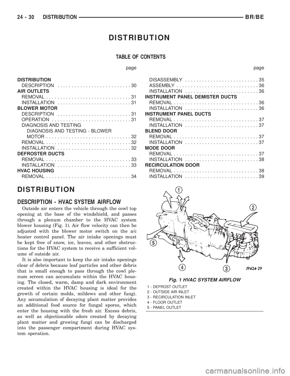
DESCRIPTION - HVAC SYSTEM AIRFLOW
Outside air enters the vehicle through the cowl top
opening at the base of the windshield, and passes
through a plenum chamber to the HVAC system
blower housing (Fig. 1). Air flow velocity can then be
adjusted with the blower motor switch on the a/c
heater control panel. The air intake openings must
be kept free of snow, ice, leaves, and other obstruc-
tions for the HVAC system to receive a sufficient vol-
ume of outside air.
It is also important to keep the air intake openings
clear of debris because leaf particles and other debris
that is small enough to pass through the cowl ple-
num screen can accumulate within the HVAC hous-
ing. The closed, warm, damp and dark environment
created within the HVAC housing is ideal for the
growth of certain molds, mildews and other fungi.
Any accumulation of decaying plant matter provides
an additional food source for fungal spores, which
enter the housing with the fresh air. Excess debris,
as well as objectionable odors created by decaying
plant matter and growing fungi can be discharged
into the passenger compartment during HVAC sys-
tem operation.
Fig. 1 HVAC SYSTEM AIRFLOW
1 - DEFROST OUTLET
2 - OUTSIDE AIR INLET
3 - RECIRCULATION INLET
4 - FLOOR OUTLET
5 - PANEL OUTLET
24 - 30 DISTRIBUTIONBR/BE
Page 2152 of 2255
AIR OUTLETS
REMOVAL - DEMISTER GRILLES
(1) Using a trim stick or another suitable wide
flat-bladed tool, gently pry at the perimeter edges of
the demister grille to release the snap features from
the instrument panel top cover.
(2) Remove the demister grille from the instru-
ment panel.
REMOVAL - PANEL OUTLET BARRELS
WARNING: THE PANEL OUTLET BARRELS
INSTALLED IN THE PASSENGER SIDE AIRBAG
DOOR PANEL OUTLET HOUSINGS MUST NEVER
BE REINSTALLED FOLLOWING REMOVAL FOR ANY
REASON. THEY MUST BE REPLACED WITH NEW
BARRELS. FAILURE TO OBSERVE THIS WARNING
COULD RESULT IN OCCUPANT INJURIES UPON
AIRBAG DEPLOYMENT.
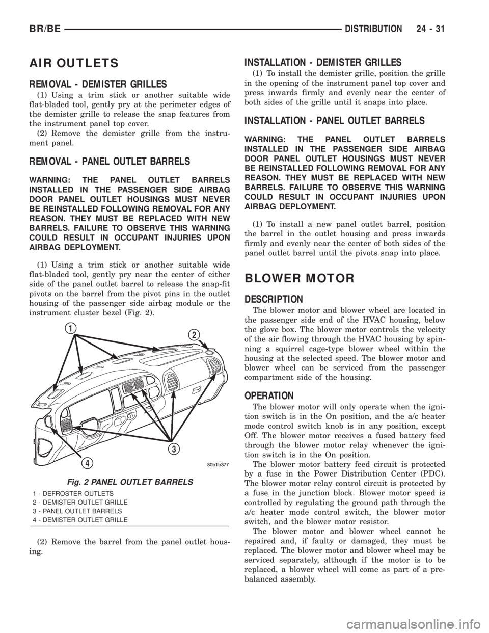
(1) Using a trim stick or another suitable wide
flat-bladed tool, gently pry near the center of either
side of the panel outlet barrel to release the snap-fit
pivots on the barrel from the pivot pins in the outlet
housing of the passenger side airbag module or the
instrument cluster bezel (Fig. 2).
(2) Remove the barrel from the panel outlet hous-
ing.
INSTALLATION - DEMISTER GRILLES
(1) To install the demister grille, position the grille
in the opening of the instrument panel top cover and
press inwards firmly and evenly near the center of
both sides of the grille until it snaps into place.
INSTALLATION - PANEL OUTLET BARRELS
WARNING: THE PANEL OUTLET BARRELS
INSTALLED IN THE PASSENGER SIDE AIRBAG
DOOR PANEL OUTLET HOUSINGS MUST NEVER
BE REINSTALLED FOLLOWING REMOVAL FOR ANY
REASON. THEY MUST BE REPLACED WITH NEW
BARRELS. FAILURE TO OBSERVE THIS WARNING
COULD RESULT IN OCCUPANT INJURIES UPON
AIRBAG DEPLOYMENT.
(1) To install a new panel outlet barrel, position
the barrel in the outlet housing and press inwards
firmly and evenly near the center of both sides of the
panel outlet barrel until the pivots snap into place.
BLOWER MOTOR
DESCRIPTION
The blower motor and blower wheel are located in
the passenger side end of the HVAC housing, below
the glove box. The blower motor controls the velocity
of the air flowing through the HVAC housing by spin-
ning a squirrel cage-type blower wheel within the
housing at the selected speed. The blower motor and
blower wheel can be serviced from the passenger
compartment side of the housing.
OPERATION
The blower motor will only operate when the igni-
tion switch is in the On position, and the a/c heater
mode control switch knob is in any position, except
Off. The blower motor receives a fused battery feed
through the blower motor relay whenever the igni-
tion switch is in the On position.
The blower motor battery feed circuit is protected
by a fuse in the Power Distribution Center (PDC).
The blower motor relay control circuit is protected by
a fuse in the junction block. Blower motor speed is
controlled by regulating the ground path through the
a/c heater mode control switch, the blower motor
switch, and the blower motor resistor.
The blower motor and blower wheel cannot be
repaired and, if faulty or damaged, they must be
replaced. The blower motor and blower wheel may be
serviced separately, although if the motor is to be
replaced, a blower wheel will come as part of a pre-
balanced assembly.
Fig. 2 PANEL OUTLET BARRELS
1 - DEFROSTER OUTLETS
2 - DEMISTER OUTLET GRILLE
3 - PANEL OUTLET BARRELS
4 - DEMISTER OUTLET GRILLE
BR/BEDISTRIBUTION 24 - 31