Page 1896 of 4323

DID99±01
DI±1694
± DIAGNOSTICSBODY CONTROL SYSTEM
1888 Author�: Date�:
2005 SEQUOIA (RM1146U)
DATA LIST / ACTIVE TEST
1. DATA LIST
HINT:
According to the DATA LIST displayed by the hand±held tester, you can read the values of the switches,
sensors, actuators and so on without parts removal. Reading the DATA LIST as a first step of troubleshooting
is one of the methods to shorten labor time.
(a) Connect the hand±held tester to the DLC3.
(b) Turn the ignition switch ON.
(c) According to the display on the tester, read the ºDATA LISTº.
BODY ECU:
ItemMeasurement Item/Display
(Range)Normal ConditionDiagnostic Note
KEY UNLK WRN SWKey unlock warning switch/ON or
OFFON: Key is in ignition key cylinder
OFF: No key is in ignition key cyl-
inder
±
ACC SWACC switch/ON or OFFON: Ignition switch ACC
OFF: Ignition switch OFF±
IG SWIG switch/ON or OFFON: Ignition switch ON
OFF: Ignition switch OFF±
PARKING BRAKE SWParking brake switch/ON or OFF
ON:
Parking brake pedal depressed
(ON)
OFF:
Parking brake released (OFF)
±
HOOD COURTSY SWHood courtesy switch/ON or OFF
ON: Engine hood OPEN
(Hood courtesy switch ON)
OFF: Engine hood CLOSED
(Hood courtesy switch OFF)
±
D DOR CTY SWDriver door courtesy light switch/
ON or OFFON: Driver door is opened
OFF: Driver door is closed±
P DOR CTY SWFront passenger door courtesy
light switch/ON or OFF
ON: Front passenger door is
opened
OFF: Front passenger door is
closed
±
Rr DOR CTY SWRear passenger door courtesy
light switch/ON or OFF
ON: Rear passenger door is
opened
OFF: Rear passenger door is
closed
±
MIRR SEL SW RRemote control mirror switch pas-
senger side/ON or OFF
ON: Remote control mirror switch
passenger side is selected
OFF: Remote control mirror switch
passenger side is not selected
±
MIRR SEL SW LRemote control mirror switch driv-
er side/ON or OFF
ON: Remote control mirror switch
driver side is selected
OFF: Remote control mirror switch
driver side is not selected
±
MIRR POS SW RRemote control mirror switch R
position/ON or OFF
ON: Remote control mirror switch
R position is selected
OFF: Remote control mirror switch
R position is not selected
±
Page 1900 of 4323

DI94R±07
I28393
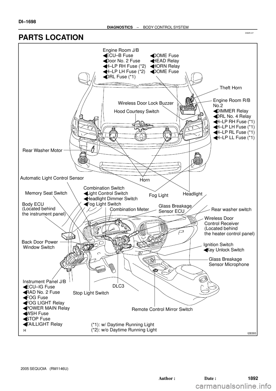
Hood Courtesy Switch Engine Room J/B
� ECU±B Fuse
� Door No. 2 Fuse
� H±LP RH Fuse (*2)
� H±LP LH Fuse (*2)
� DRL Fuse (*1)
Rear Washer Motor
Horn
Headlight
Rear washer switch
Ignition Switch
� Key Unlock Switch
DLC3 Body ECU
Instrument Panel J/B
� ECU±IG Fuse
� RAD No. 2 Fuse
� FOG Fuse
� FOG LIGHT Relay
� POWER MAIN Relay
� WSH Fuse
� STOP Fuse
� TAILLIGHT Relay Back Door Power
Window SwitchTheft Horn
Engine Room R/B
No.2
� DIMMER Relay
� DRL No. 4 Relay
� H±LP RH Fuse (*1)
� H±LP LH Fuse (*1)
� H±LP RL Fuse (*1)
� H±LP LL Fuse (*1)
Fog Light
Wireless Door
Control Receiver Wireless Door Lock Buzzer
Combination Meter Memory Seat Switch
(*1): w/ Daytime Running Light
(*2): w/o Daytime Running Light (Located behind
the instrument panel)
(Located behind
the heater control panel)
� DOME Fuse
� HEAD Relay
� HORN Relay
� DOME Fuse
Automatic Light Control Sensor
Stop Light Switch
Remote Control Mirror SwitchGlass Breakage
Sensor Microphone Glass Breakage
Sensor ECU
Combination Switch
� Light Control Switch
� Headlight Dimmer Switch
� Fog Light Switch DI±1698
± DIAGNOSTICSBODY CONTROL SYSTEM
1892 Author�: Date�:
2005 SEQUOIA (RM1146U)
PARTS LOCATION
Page 1903 of 4323
I28515
Engine Room J/B
Body ECU
Instrument Panel J/B SECURITY
I18
Ignition SWBDR
ACC
BECU S+B B6 L±W
IA5 2D
2C2H
1C 1E
1G
1L
1G
1G1C 1C 1J12
3
45
6 7
10
11
5
6 2
58 1101332
1
6L±W
IA510
B6
B7
B6 1
2 1
8
12DOOR No. 2
ECU±BShort
Pin
2W±L
W±L
W±R
B B
WGR
W±R
P RAD No. 2
AM1
WSH
ECU±IG12AM1
ACC
B7 IG1 W±L
ALT R/B
F10
FL Block
BatteryL±YB±RB±Y
B
W±BB7
B6
IE 12
IG
WIG
GND1 1W±R 12
3A 3ESub J/B No. 3
4Engine Room R/B No. 2
± DIAGNOSTICSBODY CONTROL SYSTEM
DI±1701
1895 Author�: Date�:
2005 SEQUOIA (RM1146U)
WIRING DIAGRAM
Page 1910 of 4323

I24144
Body ECU
MAINEngine Room J/B
HEAD Relay
Instrument Panel J/B
Battery
LG±R 2D
B12FL
R±W
12 532F
2G
2C
B7 1G 1JL
R±L
R±L
HRLY 8
6
1
6
1
2
(*1): w/ Daytime Running Light
(*2): w/o Daytime Running LightLG±R69 8 To Headlight RH To Headlight LH To DRL No.4 Relay To DIMMER Relay To DIMMER Relay
B 4
5 F10
FL Block(*2) (*2) (*1)
(*1)
(*1)
H±LP RH (*2)
DRL (*1)
H±LP LH (*2)
(*1) DI±1708
± DIAGNOSTICSBODY CONTROL SYSTEM
1902 Author�: Date�:
2005 SEQUOIA (RM1146U)
Headlight Relay Circuit
CIRCUIT DESCRIPTION
HEAD relay will be ºONº by operating the light control switch. The transistor which activates the HEAD relay
has two sorts: one is activated by the light control switch for fail safe and the other is activated by CPU. The
one that is activated by CPU prevents the headlight from turning off at the time of trouble with the other sys-
tem in the automatic operation circuit.
When the theft deterrent system is activated, it causes the transistor in the ECU to switch ON and OFF at
approximately 0.25 sec. intervals. This switches the HEAD relay ON and OFF, and thus flashing the head-
lights (See the wiring diagram below).
In this condition, if any of the following operations is done, the transistor in the ECU goes OFF and the HEAD
control relay switches OFF, and thus stopping the headlights flashing:
(1) Unlock the front LH or RH door with a key.
(2) Turn the ignition switch to ACC or ON position.
(3) Unlock the doors with the wireless door lock control system.
(4) Wait for approximately 60 seconds.
WIRING DIAGRAM
DI5VQ±14
Page 1915 of 4323
I28771
32
2
1
2Body ECU
2
2 L1
G±W2
2 2
Engine Room R/B No. 2R±W
21
21
21 R±L
A
To Body ECU
(HEAD Relay Circuit)B7
R
2F
B 5
EDMAINHEAD RelayDRLIA117
Battery F10
FL Block J1
J/CW±L
W±L
R±L
R±W
R±WW±B G±W
32
1 W±LW
12 A
A
A
2
22
2
12 3
5
B7 W±B
R W±B
R±LL
L 5
3
21
53
12 12 12G
2C 2D16
4 A2
22
2
2 DIMMER Relay Engine Room R/B No. 2 H5
Headlight
LH
16
17 CH±LP RH
H±ON
DIM DRL No. 4 Relay J4
J/CC H6
Headlight RH
H±LP LH
H±LP RL
H±LP LL
IA118 W±B
4Engine Room R/B No. 2
Engine Room J/B
6
LG±R R±B
J2 J/C
W±L
D1 Daytime Running
Light Resistor
J5
J/C
A
EA
± DIAGNOSTICSBODY CONTROL SYSTEM
DI±1713
1907 Author�: Date�:
2005 SEQUOIA (RM1146U)
WIRING DIAGRAM
Page 1927 of 4323
I18736
1 22014Body ECU
HCTY
B7
IA1
AJ1
J/CL±W E3
Engine Hood
Courtesy SW
W±B
EA L±W
± DIAGNOSTICSBODY CONTROL SYSTEM
DI±1725
1919 Author�: Date�:
2005 SEQUOIA (RM1146U)
Engine Hood Courtesy Switch Circuit
CIRCUIT DESCRIPTION
The engine hood courtesy switch is built into the engine hood lock assembly, and is turned on when the en-
gine hood is opened and goes off when the engine hood is closed.
WIRING DIAGRAM
DI7NV±08
Page 1928 of 4323

I00298
1 (+)
2 (±)
DI±1726
± DIAGNOSTICSBODY CONTROL SYSTEM
1920 Author�: Date�:
2005 SEQUOIA (RM1146U)
INSPECTION PROCEDURE
HINT:
When using the hand±held tester, start the inspection from step 1 and when not using the hand±held tester,
start from step 2.
1 Check engine hood courtesy switch using hand±held tester.
PREPARATION:
(a) Connect the hand±held tester to the DLC3.
(b) Turn the ignition switch ON.
CHECK:
According to the display on the tester, read the ºDATA LISTº.
BODY ECU:
ItemMeasurement Item/Display
(Range)Normal ConditionDiagnostic Note
HOOD COURTSY SWHood courtesy switch/ON or OFF
ON: Engine hood OPEN
(Hood courtesy switch ON)
OFF: Engine hood CLOSE
(Hood courtesy switch OFF)
±
OK:
The indication on the tester switches between ON and OFF in accordance with the engine hood
courtesy switch status.
OK Proceed to next circuit inspection shown in
problem symptoms table (See page DI±1686).
NG
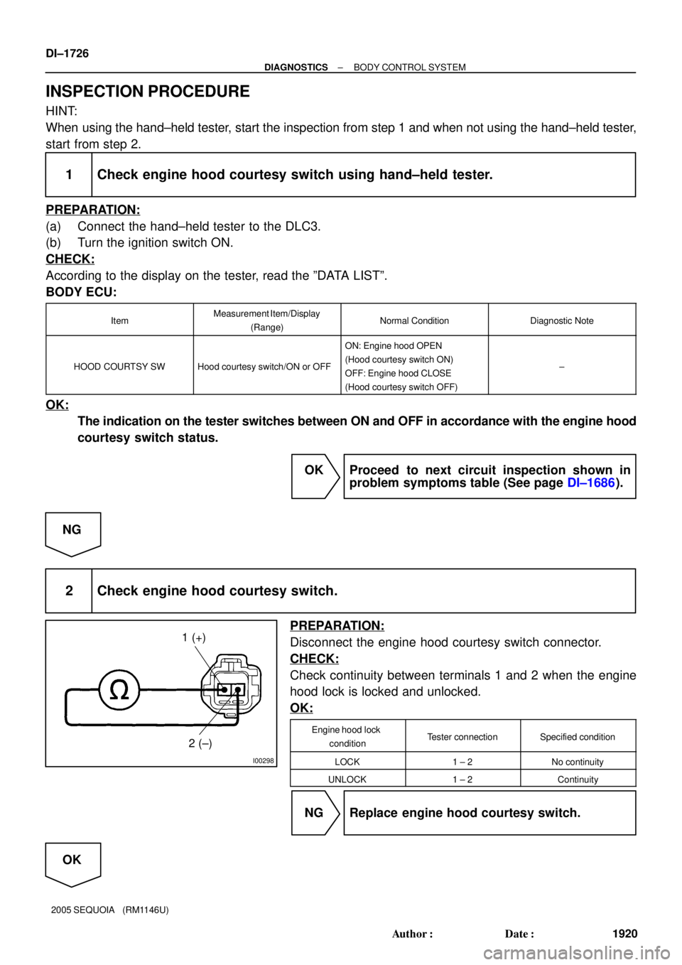
2 Check engine hood courtesy switch.
PREPARATION:
Disconnect the engine hood courtesy switch connector.
CHECK:
Check continuity between terminals 1 and 2 when the engine
hood lock is locked and unlocked.
OK:
Engine hood lock
conditionTester connectionSpecified condition
LOCK1 ± 2No continuity
UNLOCK1 ± 2Continuity
NG Replace engine hood courtesy switch.
OK
Page 1939 of 4323
I24356
32
1J 1E W±RBody ECU
RDA ECU±B
4
52D
5
4
B5PRG B
OW±R
B5 5
IG1
BatterySHORT PIN Engine Room J/B
1
2C8
Sub J/B No. 3
3A2
3A1
RDA PRG W2
Wireless Door
Control Receiver
+B
EV
R±G 3
2 W±RInstrument Panel J/B
F10
Fusible
Link
Block
BW±R
A J43
J/C
O
A
± DIAGNOSTICSBODY CONTROL SYSTEM
DI±1737
1931 Author�: Date�:
2005 SEQUOIA (RM1146U)
Wireless door lock receiver circuit
CIRCUIT DESCRIPTION
The signal from the transmitter is sent to the body ECU through RDA line of the wireless door control receiver.
RDA line is diagnosed by the body ECU, check DTC also in case of the failure of the wireless function.
WIRING DIAGRAM
DI6LV±13