Page 1900 of 4323

� H±LP LH Fuse (*2)
� DRL Fuse (*1)
Rear Washer Motor
Horn
Headlight
Rear washer switch
Igni")
DI94R±07
I28393
Hood Courtesy Switch Engine Room J/B
� ECU±B Fuse
� Door No. 2 Fuse
� H±LP RH Fuse (*2)
� H±LP LH Fuse (*2)
� DRL Fuse (*1)
Rear Washer Motor
Horn
Headlight
Rear washer switch
Ignition Switch
� Key Unlock Switch
DLC3 Body ECU
Instrument Panel J/B
� ECU±IG Fuse
� RAD No. 2 Fuse
� FOG Fuse
� FOG LIGHT Relay
� POWER MAIN Relay
� WSH Fuse
� STOP Fuse
� TAILLIGHT Relay Back Door Power
Window SwitchTheft Horn
Engine Room R/B
No.2
� DIMMER Relay
� DRL No. 4 Relay
� H±LP RH Fuse (*1)
� H±LP LH Fuse (*1)
� H±LP RL Fuse (*1)
� H±LP LL Fuse (*1)
Fog Light
Wireless Door
Control Receiver Wireless Door Lock Buzzer
Combination Meter Memory Seat Switch
(*1): w/ Daytime Running Light
(*2): w/o Daytime Running Light (Located behind
the instrument panel)
(Located behind
the heater control panel)
� DOME Fuse
� HEAD Relay
� HORN Relay
� DOME Fuse
Automatic Light Control Sensor
Stop Light Switch
Remote Control Mirror SwitchGlass Breakage
Sensor Microphone Glass Breakage
Sensor ECU
Combination Switch
� Light Control Switch
� Headlight Dimmer Switch
� Fog Light Switch DI±1698
± DIAGNOSTICSBODY CONTROL SYSTEM
1892 Author�: Date�:
2005 SEQUOIA (RM1146U)
PARTS LOCATION
Page 1908 of 4323

I24351
Body ECU
11 3
21 5
B 5W
1G TAILLIGHT Relay
To Taillight
F10
Fusible Link BlockLG
B7
ALTTRLY 2 1L
81
BatteryInstrument Panel J/B
LG
DDJ/9
J/C DI±1706
± DIAGNOSTICSBODY CONTROL SYSTEM
1900 Author�: Date�:
2005 SEQUOIA (RM1146U)
Taillight Relay Circuit
CIRCUIT DESCRIPTION
TAILLIGHT relay will be ºONº by operating the light control switch. The transistor which activates the tail light
relay has two sorts: one is activated by the light control switch for fail safe and the other is activated by CPU.
When the theft deterrent system is activated, it causes the transistor in the ECU to switch ON and OFF at
approximately 0.4 sec. intervals. This switches the TAILLIGHT relay ON and OFF, and thus flashing the tail-
lights (See the wiring diagram below).
In this condition, if any of the following operations is done, the transistor in the ECU goes OFF and the TAIL-
LIGHT relay switches OFF, and thus stopping the taillights flashing:
(1) Unlock the front LH or RH door with a key.
(2) Turn the ignition switch to ACC or ON position.
(3) Unlock the doors with the wireless door lock control system.
(4) Wait for approximately 60 seconds.
WIRING DIAGRAM
DI6QY±15
Page 1910 of 4323
: w/ Daytime Running Light
(*2): w/o Daytime Runn")
I24144
Body ECU
MAINEngine Room J/B
HEAD Relay
Instrument Panel J/B
Battery
LG±R 2D
B12FL
R±W
12 532F
2G
2C
B7 1G 1JL
R±L
R±L
HRLY 8
6
1
6
1
2
(*1): w/ Daytime Running Light
(*2): w/o Daytime Running LightLG±R69 8 To Headlight RH To Headlight LH To DRL No.4 Relay To DIMMER Relay To DIMMER Relay
B 4
5 F10
FL Block(*2) (*2) (*1)
(*1)
(*1)
H±LP RH (*2)
DRL (*1)
H±LP LH (*2)
(*1) DI±1708
± DIAGNOSTICSBODY CONTROL SYSTEM
1902 Author�: Date�:
2005 SEQUOIA (RM1146U)
Headlight Relay Circuit
CIRCUIT DESCRIPTION
HEAD relay will be ºONº by operating the light control switch. The transistor which activates the HEAD relay
has two sorts: one is activated by the light control switch for fail safe and the other is activated by CPU. The
one that is activated by CPU prevents the headlight from turning off at the time of trouble with the other sys-
tem in the automatic operation circuit.
When the theft deterrent system is activated, it causes the transistor in the ECU to switch ON and OFF at
approximately 0.25 sec. intervals. This switches the HEAD relay ON and OFF, and thus flashing the head-
lights (See the wiring diagram below).
In this condition, if any of the following operations is done, the transistor in the ECU goes OFF and the HEAD
control relay switches OFF, and thus stopping the headlights flashing:
(1) Unlock the front LH or RH door with a key.
(2) Turn the ignition switch to ACC or ON position.
(3) Unlock the doors with the wireless door lock control system.
(4) Wait for approximately 60 seconds.
WIRING DIAGRAM
DI5VQ±14
Page 1917 of 4323
I24352
Body ECU
B5KSW
IGU1
Key Unlock Warning Switch
O1
2
Y±G13
A
AJ43
J/C
O
± DIAGNOSTICSBODY CONTROL SYSTEM
DI±1715
1909 Author�: Date�:
2005 SEQUOIA (RM1146U)
Key unlock warning switch circuit
CIRCUIT DESCRIPTION
The key unlock warning switch turns on when the ignition key is inserted into the key cylinder and turns off
when the key is removed.
WIRING DIAGRAM
DI571±11
Page 1918 of 4323
DI±1716
± DIAGNOSTICSBODY CONTROL SYSTEM
1910 Author�: Date�:
2005 SEQUOIA (RM1146U)
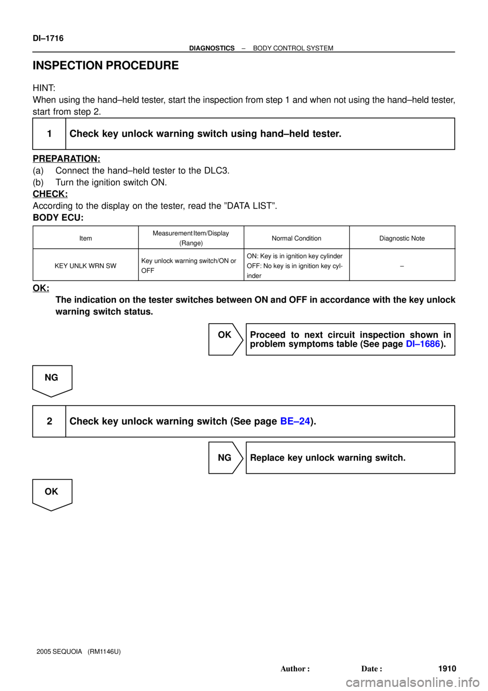
INSPECTION PROCEDURE
HINT:
When using the hand±held tester, start the inspection from step 1 and when not using the hand±held tester,
start from step 2.
1 Check key unlock warning switch using hand±held tester.
PREPARATION:
(a) Connect the hand±held tester to the DLC3.
(b) Turn the ignition switch ON.
CHECK:
According to the display on the tester, read the ºDATA LISTº.
BODY ECU:
ItemMeasurement Item/Display
(Range)Normal ConditionDiagnostic Note
KEY UNLK WRN SWKey unlock warning switch/ON or
OFFON: Key is in ignition key cylinder
OFF: No key is in ignition key cyl-
inder
±
OK:
The indication on the tester switches between ON and OFF in accordance with the key unlock
warning switch status.
OK Proceed to next circuit inspection shown in
problem symptoms table (See page DI±1686).
NG
2 Check key unlock warning switch (See page BE±24).
NG Replace key unlock warning switch.
OK
Page 1919 of 4323
± DIAGNOSTICSBODY CONTROL SYSTEM
DI±1717
1911 Author�: Date�:
2005 SEQUOIA (RM1146U)
3 Check wire harness and connector between key unlock warning switch and
body ECU, key unlock warning switch and body ground (See page IN±35).
NG Repair or replace wire harness or connector.
OK
Proceed to next circuit inspection shown in
problem symptoms table
(See page DI±1686).
Page 1933 of 4323
I18742
Body ECU
IEW±BIND 12
A17
BR
J8
J/CGR 9
1F 1D6
C6C5 Combination Meter
16
B5 Security Instrument Panel J/B
± DIAGNOSTICSBODY CONTROL SYSTEM
DI±1731
1925 Author�: Date�:
2005 SEQUOIA (RM1146U)
Theft deterrent indicator circuit
CIRCUIT DESCRIPTION
When the theft deterrent system is preparing to set, this circuit turns on the indicator light. When the system
has been set, it continually turns the indicator light on for 1 second and turns it off for 1 second, and thus
blinking the indicator light.
This theft deterrent indicator sends a key judgment of the immobilizer to the transponder key ECU.
WIRING DIAGRAM
DI579±09
Page 1962 of 4323
I28523
Back Door ECU
Sub J/B No. 3 ILE
B118
BF18
BD29
WWWW
J30J/C
J29 FMInstrument Panel J/BBody ECU
1G6
1G5
1M10
1E3
1G13
1G14
1E81M6
1J5ILE B73
1F 10
1M7W
3C
3A3A
3D6 6
16 6I17
Ignition Key
Cylinder Light
12W
R
R6R
J48R
J/C
J49
BC1 LF R
D13 Door Courtesy
Light Rear RH
12
D17 Door Courtesy
Light Switch Rear RH2 1
W±B
BA161
2
2
IN1R
A AJ21
J/C R
R 1B±O
2 1 D8 Diode
(Interior Light No. 1)BC17
R±YR±YW±B RW±B W±BRRRW (*1)
W (*2)
W
R
12 S8 Step Light
V7 Vanity Light RH
V6 Vanity Light LH
R11 Rear Interior Light
(*4) (*3) To Dome Fuse
W±B
W±B
W
G±R(*2)
(*2)
(*2) 1
2
4
de f g bc aR
(*2)
3ON
DoorOFF R
R DI±1760
± DIAGNOSTICSBODY CONTROL SYSTEM
1954 Author�: Date�:
2005 SEQUOIA (RM1146U)
WIRING DIAGRAM
(*1): w/o Sliding Roof, RSE and RSA
(*2): w/ Sliding Roof, RSE or RSA
(*3): w/ Sliding Roof w/ RSE or RSA
(*4): w/ Sliding Roof w/o RSE and RSA