Page 1796 of 4323
DI±1594
± DIAGNOSTICSENGINE IMMOBILISER SYSTEM
1788 Author�: Date�:
2005 SEQUOIA (RM1146U)
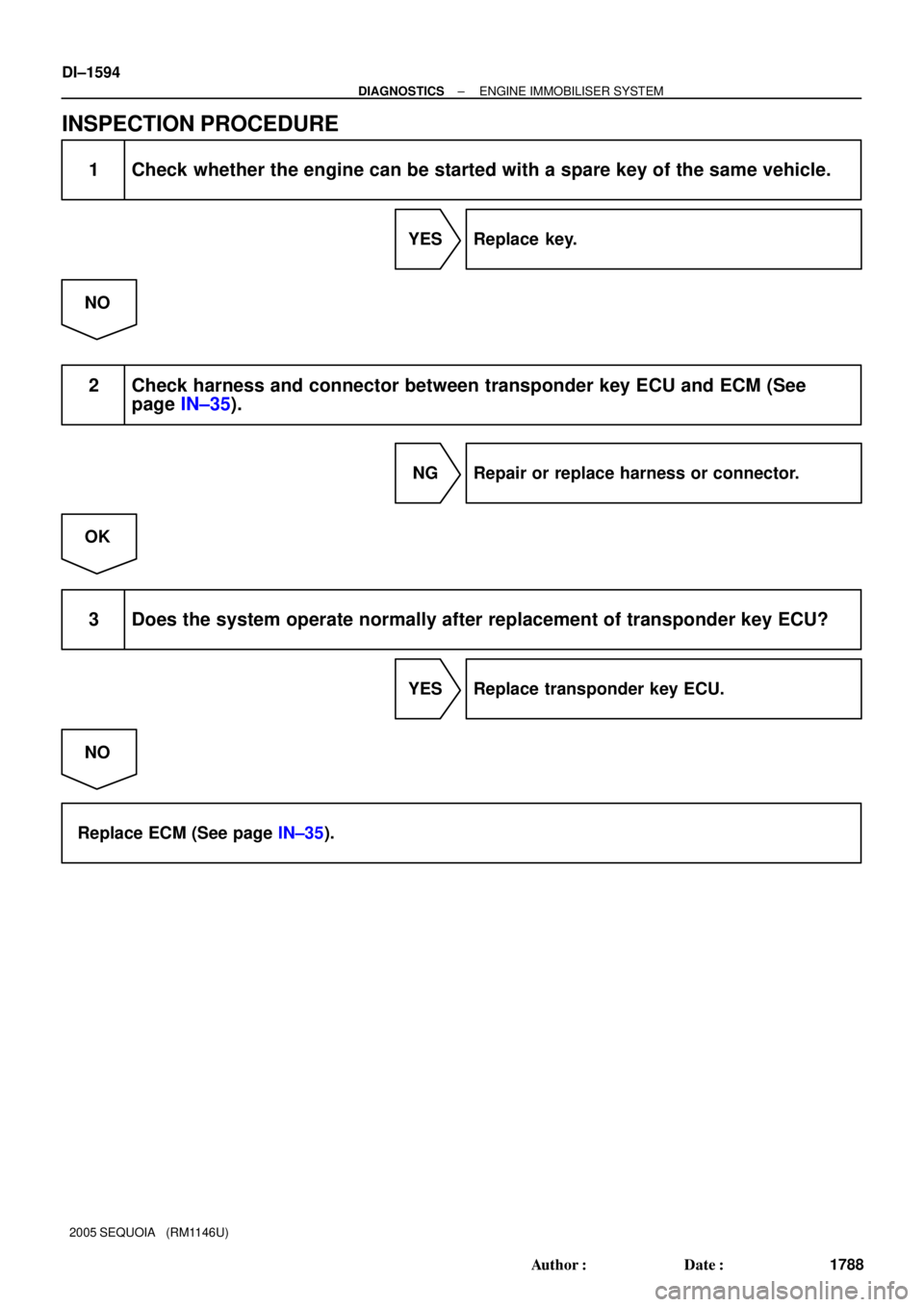
INSPECTION PROCEDURE
1 Check whether the engine can be started with a spare key of the same vehicle.
YES Replace key.
NO
2 Check harness and connector between transponder key ECU and ECM (See
page IN±35).
NG Repair or replace harness or connector.
OK
3 Does the system operate normally after replacement of transponder key ECU?
YES Replace transponder key ECU.
NO
Replace ECM (See page IN±35).
Page 1797 of 4323
I24831
Transponder Key ECU
Sub J/B No. 3
+B
J43
J/C
51
O
BatteryF10
FL BlockW±R
B
4
IG BEngine Room J/B W±R32
1J
1E Instrument Panel J/B
A
AGND O14
T16 T16 1
2
W±R
3A 3B
81
2C
2D ECU±B
SHORT PIN
± DIAGNOSTICSENGINE IMMOBILISER SYSTEM
DI±1595
1789 Author�: Date�:
2005 SEQUOIA (RM1146U)
Power source circuit
CIRCUIT DESCRIPTION
This circuit provides power to operate the transponder key ECU.
WIRING DIAGRAM
DI7TO±07
Page 1798 of 4323
DI±1596
± DIAGNOSTICSENGINE IMMOBILISER SYSTEM
1790 Author�: Date�:
2005 SEQUOIA (RM1146U)
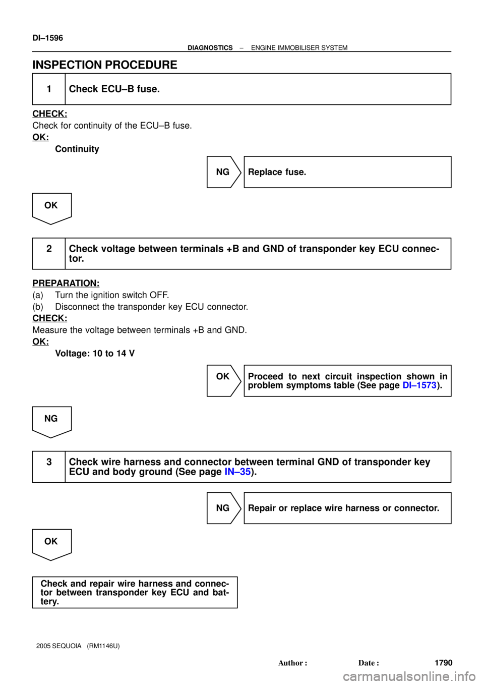
INSPECTION PROCEDURE
1 Check ECU±B fuse.
CHECK:
Check for continuity of the ECU±B fuse.
OK:
Continuity
NG Replace fuse.
OK
2 Check voltage between terminals +B and GND of transponder key ECU connec-
tor.
PREPARATION:
(a) Turn the ignition switch OFF.
(b) Disconnect the transponder key ECU connector.
CHECK:
Measure the voltage between terminals +B and GND.
OK:
Voltage: 10 to 14 V
OK Proceed to next circuit inspection shown in
problem symptoms table (See page DI±1573).
NG
3 Check wire harness and connector between terminal GND of transponder key
ECU and body ground (See page IN±35).
NG Repair or replace wire harness or connector.
OK
Check and repair wire harness and connec-
tor between transponder key ECU and bat-
tery.
Page 1799 of 4323
I24835
Instrument Panel J/B
6 9
BR
1F 1D W±B
A
IEJ8
J/C12
C6C516
LG±B7
T16IND Combination MeterTransponder Key ECU
Security
± DIAGNOSTICSENGINE IMMOBILISER SYSTEM
DI±1597
1791 Author�: Date�:
2005 SEQUOIA (RM1146U)
Security Indicator Light Circuit
CIRCUIT DESCRIPTION
When the transponder key is registered, the transponder key ECU outputs the key registration condition by
illuminating, blinking or turning off the security indicator.
WIRING DIAGRAM
DIABJ±03
Page 1800 of 4323
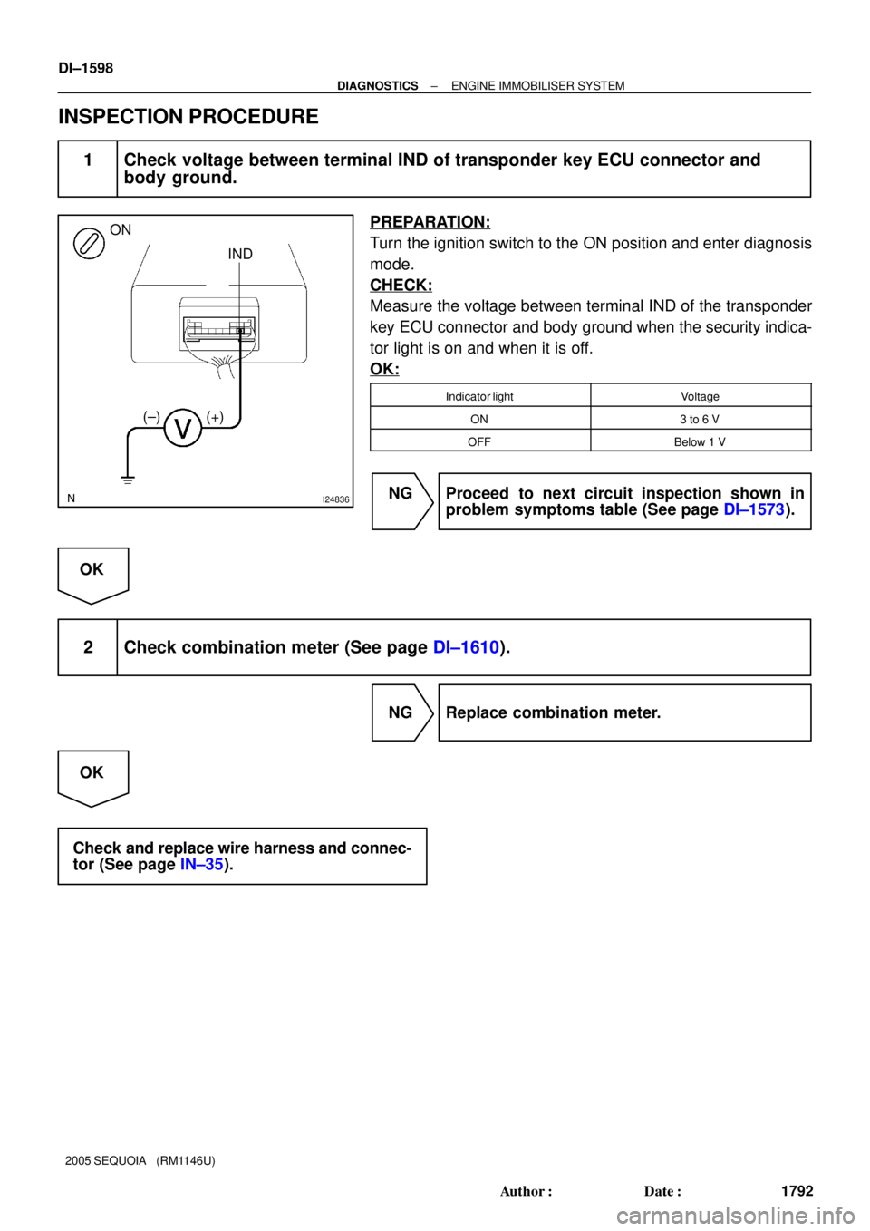
I24836
ON
IND
(±) (+)
DI±1598
± DIAGNOSTICSENGINE IMMOBILISER SYSTEM
1792 Author�: Date�:
2005 SEQUOIA (RM1146U)
INSPECTION PROCEDURE
1 Check voltage between terminal IND of transponder key ECU connector and
body ground.
PREPARATION:
Turn the ignition switch to the ON position and enter diagnosis
mode.
CHECK:
Measure the voltage between terminal IND of the transponder
key ECU connector and body ground when the security indica-
tor light is on and when it is off.
OK:
Indicator lightVoltage
ON3 to 6 V
OFFBelow 1 V
NG Proceed to next circuit inspection shown in
problem symptoms table (See page DI±1573).
OK
2 Check combination meter (See page DI±1610).
NG Replace combination meter.
OK
Check and replace wire harness and connec-
tor (See page IN±35).
Page 1801 of 4323
I24837
IGTransponder Key ECU
D 3
T16
OJ43
J/C W±L
8 OP3 D6
DLC3
CG
4A
AO
± DIAGNOSTICSENGINE IMMOBILISER SYSTEM
DI±1599
1793 Author�: Date�:
2005 SEQUOIA (RM1146U)
Diagnosis Circuit
CIRCUIT DESCRIPTION
This circuit sends a signal to the ECU that outputs DTCs.
WIRING DIAGRAM
DIABK±03
Page 1802 of 4323
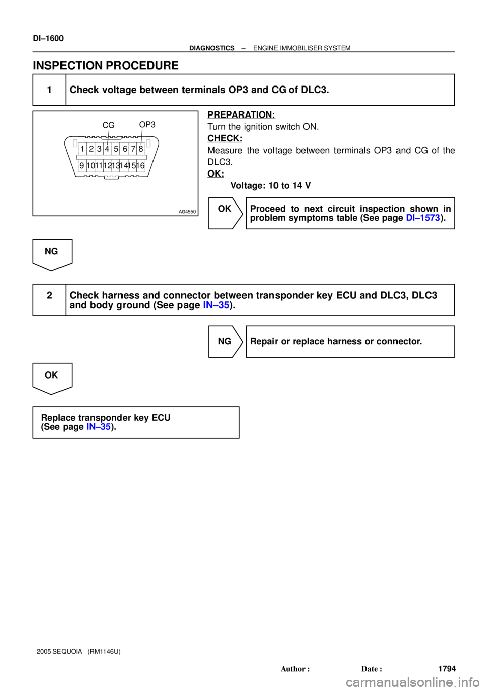
A04550
CGOP3
1 234 5 678
91011 13 151612 14
DI±1600
± DIAGNOSTICSENGINE IMMOBILISER SYSTEM
1794 Author�: Date�:
2005 SEQUOIA (RM1146U)
INSPECTION PROCEDURE
1 Check voltage between terminals OP3 and CG of DLC3.
PREPARATION:
Turn the ignition switch ON.
CHECK:
Measure the voltage between terminals OP3 and CG of the
DLC3.
OK:
Voltage: 10 to 14 V
OK Proceed to next circuit inspection shown in
problem symptoms table (See page DI±1573).
NG
2 Check harness and connector between transponder key ECU and DLC3, DLC3
and body ground (See page IN±35).
NG Repair or replace harness or connector.
OK
Replace transponder key ECU
(See page IN±35).
Page 1807 of 4323
DID8P±01
I28566
Seat Position
Control ECU
A/C ECU (Integration
Control Panel) BEANBody ECU
Back Door ECU
ECM
Light Control
Rheostat
Vehicle Speed
Sensor
Oil Pressure
Sender Gauge
Fuel Sender Gauge
Seat Inner
Belt Switch
Park/neutral
Position Switch
Turn Signal
Flasher Relay
Washer Level SensorKey Unlock
Warning Switch
Door Courtesy
Lamp Switch
Parking Brake Switch
Transponder
Key ECU
4WD Control ECU
Airbag Sensor
Center ECU Combination
Meter
Skid Control ECU
Suspension
Control ECU
Translate ECU
Overhead Module
(Garage Door
Opener)BEAN
BEAN
BEAN
BEAN
BEAN BEAN
± DIAGNOSTICSCOMBINATION METER SYSTEM
DI±1605
1799 Author�: Date�:
2005 SEQUOIA (RM1146U)
SYSTEM DIAGRAM


 BEANBody ECU
Back Door ECU
ECM
Light Control
Rheostat
Vehicle Speed
Sensor
Oil Pressure
Sender Gauge
Fuel Sender Gau")