Page 1778 of 4323

DID51±01
A04550
CG
OP3
DLC3 12345678
9
1011
13 1516 12 14
TC
I28427
Security Indicator
Light MIL
BR3904
Normal System Code
0.25 Sec.0.25 Sec.
I02680
Diagnostic Trouble Code (Example Code 12, 99)
0.5 Sec. 0.5 Sec.
1.5 Sec. 2.5 Sec.
One Cycle4.5 Sec.Repeat
DI±1576
± DIAGNOSTICSENGINE IMMOBILISER SYSTEM
1770 Author�: Date�:
2005 SEQUOIA (RM1146U)
DTC CHECK / CLEAR
1. INSPECT DIAGNOSIS
(a) Check the DTC using SST check wire.
(1) Turn the ignition switch ON, but do not start the en-
gine.
(2) When checking DTC 99: Using SST, connect termi-
nals 13 (TC) and 4 (CG) of the DLC3.
(3) When checking codes except DTC 99: Using SST,
connect terminals 8 (OP3) and 4 (CG) of the DLC3.
SST 09843±18040
(4) Read the DTC indicated by the number of times the
security indicator light or the MIL blinks.
HINT:
�If no DTC is output, inspect the diagnosis circuits (OP3
and TC) and the security indicator light circuit (See page
DI±1597, DI±1567, DI±1599).
�If the system is operating normally, the light blinks twice
per second.
�As an example, the blinking patterns of the normal system
code and trouble codes 12 and 99 are shown on the left
and below.
Page 1802 of 4323
A04550
CGOP3
1 234 5 678
91011 13 151612 14
DI±1600
± DIAGNOSTICSENGINE IMMOBILISER SYSTEM
1794 Author�: Date�:
2005 SEQUOIA (RM1146U)
INSPECTION PROCEDURE
1 Check voltage between terminals OP3 and CG of DLC3.
PREPARATION:
Turn the ignition switch ON.
CHECK:
Measure the voltage between terminals OP3 and CG of the
DLC3.
OK:
Voltage: 10 to 14 V
OK Proceed to next circuit inspection shown in
problem symptoms table (See page DI±1573).
NG
2 Check harness and connector between transponder key ECU and DLC3, DLC3
and body ground (See page IN±35).
NG Repair or replace harness or connector.
OK
Replace transponder key ECU
(See page IN±35).
Page 1928 of 4323

I00298
1 (+)
2 (±)
DI±1726
± DIAGNOSTICSBODY CONTROL SYSTEM
1920 Author�: Date�:
2005 SEQUOIA (RM1146U)
INSPECTION PROCEDURE
HINT:
When using the hand±held tester, start the inspection from step 1 and when not using the hand±held tester,
start from step 2.
1 Check engine hood courtesy switch using hand±held tester.
PREPARATION:
(a) Connect the hand±held tester to the DLC3.
(b) Turn the ignition switch ON.
CHECK:
According to the display on the tester, read the ºDATA LISTº.
BODY ECU:
ItemMeasurement Item/Display
(Range)Normal ConditionDiagnostic Note
HOOD COURTSY SWHood courtesy switch/ON or OFF
ON: Engine hood OPEN
(Hood courtesy switch ON)
OFF: Engine hood CLOSE
(Hood courtesy switch OFF)
±
OK:
The indication on the tester switches between ON and OFF in accordance with the engine hood
courtesy switch status.
OK Proceed to next circuit inspection shown in
problem symptoms table (See page DI±1686).
NG
2 Check engine hood courtesy switch.
PREPARATION:
Disconnect the engine hood courtesy switch connector.
CHECK:
Check continuity between terminals 1 and 2 when the engine
hood lock is locked and unlocked.
OK:
Engine hood lock
conditionTester connectionSpecified condition
LOCK1 ± 2No continuity
UNLOCK1 ± 2Continuity
NG Replace engine hood courtesy switch.
OK
Page 2105 of 4323

DIDF8±01
C00083DLC3
± DIAGNOSTICSMULTIPLEX COMMUNICATION SYSTEM
DI±1903
2097 Author�: Date�:
2005 SEQUOIA (RM1146U)
DIAGNOSIS SYSTEM
1. DIAGNOSIS SYSTEM
(a) Inspect the battery voltage.
Battery voltage: 11 to 14 V
If voltage is below 11 V, recharge the battery before proceeding.
(b) Check the DLC3.
The body ECU uses ISO 9141±2 for communication. The
terminal arrangement of the DLC3 complies with SAE
J1962 and matches the ISO 9141±2 format.
Verify the conditions listed in the table below:
Symbols (Terminals No.)Terminal DescriptionConditionSpecified Condition
SIL(7) ± SG(5)Bus º+º lineDuring communicationPulse generation
SG(5) ± Body groundSignal groundAlwaysBelow 1 W
BAT(16) ± Body groundBattery positiveAlways11 to 14 V
HINT:
If the hand±held tester display shows UNABLE TO CONNECT
TO VEHICLE when the cable of the hand±held tester is con-
nected to the DLC3, the ignition switch is turned to the ON posi-
tion and the tester is operated, there is a problem on either the
vehicle side or the tester side.
�If communication is normal when the tester is connected
to another vehicle, inspect the DLC3 on the original ve-
hicle.
�If communication is still not possible when the tool is con-
nected to another vehicle, the problem is probably in the
tester itself, so consult the Service Department listed in
the tester's instruction manual.
Page 2596 of 4323
EM0KT±11
D13872
Hand±Held Tester
DLC3
CAN VIM
A08769
A23394
TC
SST
DLC3
CG
± ENGINE MECHANICALIGNITION TIMING
EM±9
2588 Author�: Date�:
2005 SEQUOIA (RM1146U)
IGNITION TIMING
INSPECTION
1. WARM UP ENGINE
Allow the engine to warm up to normal operating temperature.
2. INSPECT IGNITION TIMING
(a) When using a hand±held tester.
(1) Connect a hand±held tester to the Controller Area
Network Vehicle Interface Module (CAN VIM). Then
connect the CAN VIM to the Date Link Connector 3
(DLC3).
(2) Please refer to the hand±held tester operator's
manual for further details.
Ignition timing: 5 to 15° BTDC at idle
(Transmission in neutral)
(3) Disconnect the hand±held tester and CAN VIM
from the DLC3.
(b) When not using a hand±held tester.
(1) Connect the tester probe of a timing light to the wire
(black ± red) of the ignition coil connector for the
No.1 cylinder.
(2) Using SST, connect terminals TC and CG of the
DLC3.
SST 09843±18040
Page 2726 of 4323

B16489
Battery
B06545
Vacuum Gauge
B17595
EC±10
± EMISSION CONTROLEVAPORATIVE EMISSION (EVAP) CONTROL SYSTEM
2718 Author�: Date�:
2005 SEQUOIA (RM1146U)
(d) When not using a hand±held tester:
Operation of the VSV for the EVAP.
(1) Disconnect the VSV for the EVAP connector.
(2) Connect leads from the positive (+) and negative (±)
battery terminals to the VSV for EVAP terminals.
(3) Start the engine.
(e) Check the vacuum when the engine idles.
Vacuum:
Maintain between 0.368 and 19.713 in.Hg (5 to 268
in.Aq) for over 5 seconds
HINT:
If the vacuum does not change, the hose connecting the VSV
and the service port is loose or blocked, or the VSV is malfunc-
tioning.
(f) When using a hand±held tester:
Conclude operation of the VSV for EVAP.
(1) Stop the engine.
(2) Disconnect the hand±held tester from the DLC3.
(g) When not using a hand±held tester:
Conclude operation of the VSV for EVAP.
(1) Stop the engine.
(2) Disconnect the positive (+) and negative (±) leads
of the battery from the VSV for EVAP terminals.
(3) Connect the VSV for EVAP connector.
(h) Disconnect the vacuum gauge from the EVAP service
port on the purge line.
(i) Connect a pressure gauge to the EVAP service port on
the purge line.
(j) Check the pressure.
(1) Prepare a rubber hose that has an inside diameter
of 15 to 18.5 mm.
(2) Disconnect the atmospheric side hose of the pump
module.
(3) Connect the prepared rubber hose to the pump
module, and pinch the rubber hose with the clip to
prevent air from entering into the canister passage.
Page 2780 of 4323

B17464
3 2 1
45
±20 0 20 40 60 80 100 0.1 0.2 0.3 0.51
2 3 5 10 20 30
TEMPERATURE�C(�F)
RESISTANCE kW
(±4) (32) (68) (140)(104)(212)
(176)
Air
E2 THA VG E2G
+B
Acceptable
SF0P2±09
B17465
Air
B17466
ECM
VG
E2G
Voltmeter
SF±38
± SFIMASS AIR FLOW (MAF) METER
2772 Author�: Date�:
2005 SEQUOIA (RM1146U)
INSPECTION
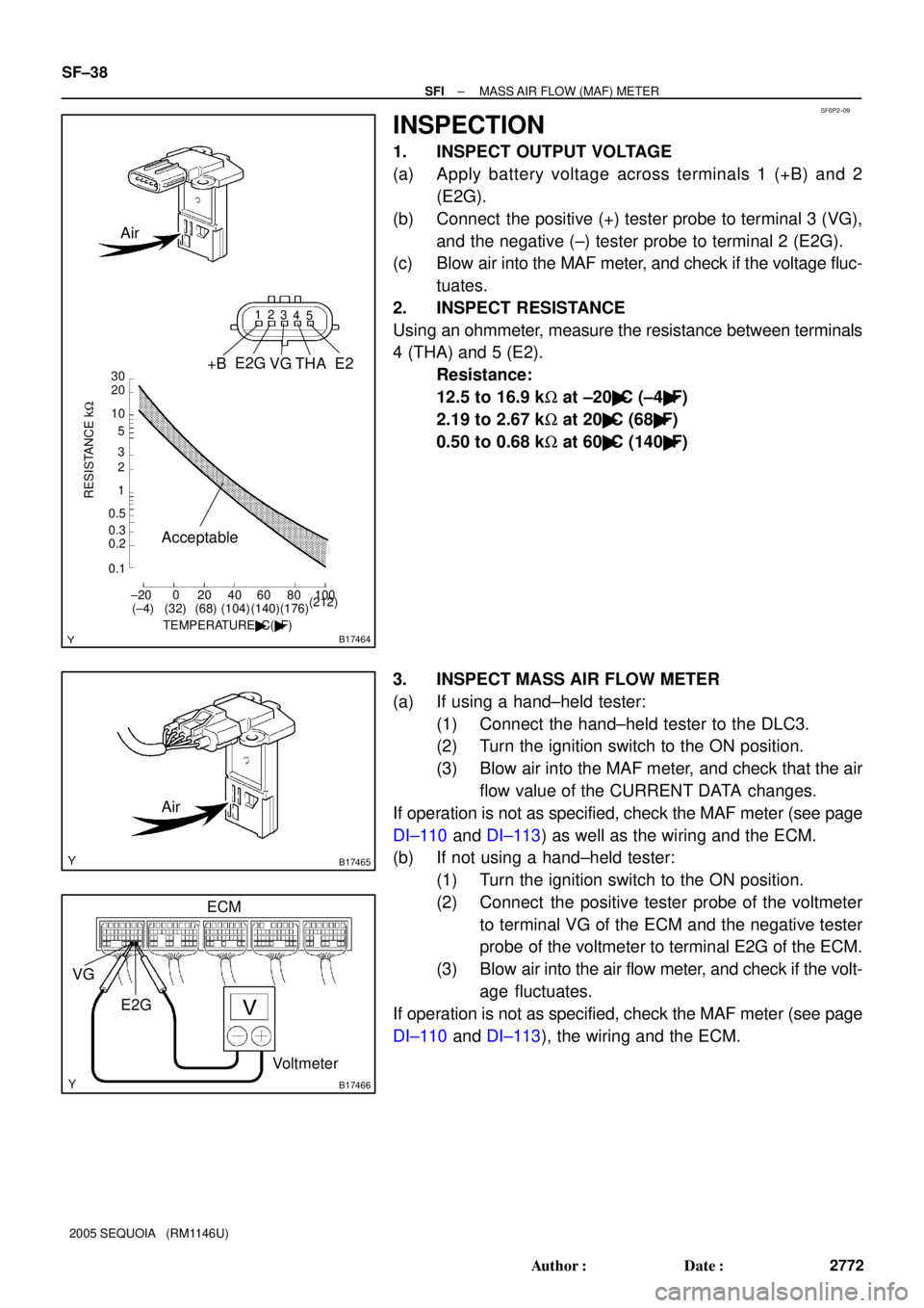
1. INSPECT OUTPUT VOLTAGE
(a) Apply battery voltage across terminals 1 (+B) and 2
(E2G).
(b) Connect the positive (+) tester probe to terminal 3 (VG),
and the negative (±) tester probe to terminal 2 (E2G).
(c) Blow air into the MAF meter, and check if the voltage fluc-
tuates.
2. INSPECT RESISTANCE
Using an ohmmeter, measure the resistance between terminals
4 (THA) and 5 (E2).
Resistance:
12.5 to 16.9 kW at ±20�C (±4�F)
2.19 to 2.67 kW at 20�C (68�F)
0.50 to 0.68 kW at 60�C (140�F)
3. INSPECT MASS AIR FLOW METER
(a) If using a hand±held tester:
(1) Connect the hand±held tester to the DLC3.
(2) Turn the ignition switch to the ON position.
(3) Blow air into the MAF meter, and check that the air
flow value of the CURRENT DATA changes.
If operation is not as specified, check the MAF meter (see page
DI±110 and DI±113) as well as the wiring and the ECM.
(b) If not using a hand±held tester:
(1) Turn the ignition switch to the ON position.
(2) Connect the positive tester probe of the voltmeter
to terminal VG of the ECM and the negative tester
probe of the voltmeter to terminal E2G of the ECM.
(3) Blow air into the air flow meter, and check if the volt-
age fluctuates.
If operation is not as specified, check the MAF meter (see page
DI±110 and DI±113), the wiring and the ECM.
Page 2781 of 4323

B17467
SF1XJ±01
D13872
Hand±Held Tester
DLC3
CAN VIM
± SFITHROTTLE BODY
SF±39
2773 Author�: Date�:
2005 SEQUOIA (RM1146U)
THROTTLE BODY
ON±VEHICLE INSPECTION
1. REMOVE THROTTLE BODY COVER
2. INSPECT SYSTEM OPERATION
(a) Inspect the throttle control motor for operating sound.
(1) Turn the ignition switch ON.
(2) When depressing the accelerator pedal, check the
running sound of the motor. Also, check that there
is no friction sound.
If operation is not as specified, check the throttle control motor
(see step 3), wiring and ECM.
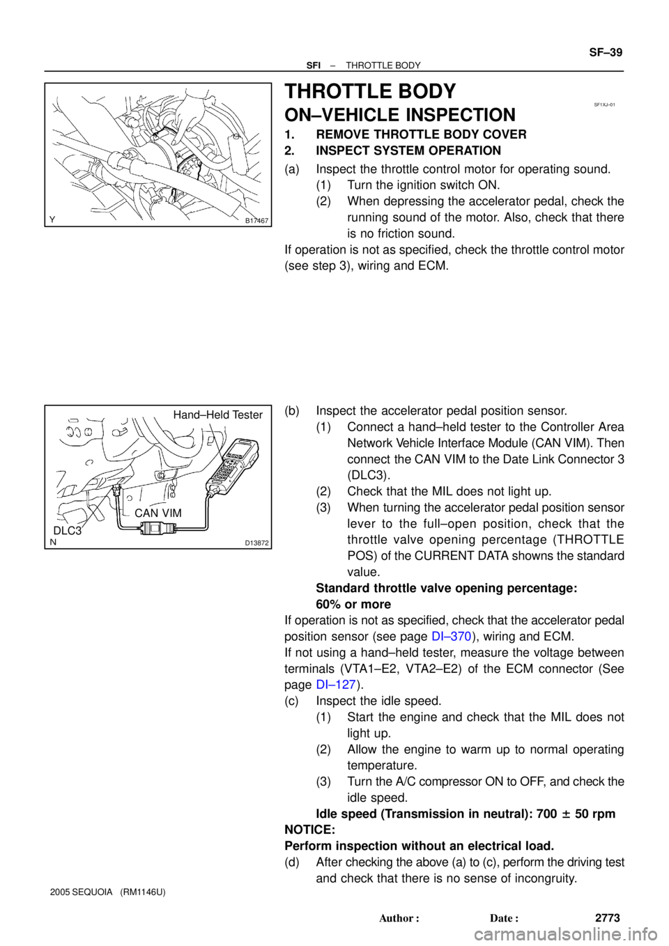
(b) Inspect the accelerator pedal position sensor.
(1) Connect a hand±held tester to the Controller Area
Network Vehicle Interface Module (CAN VIM). Then
connect the CAN VIM to the Date Link Connector 3
(DLC3).
(2) Check that the MIL does not light up.
(3) When turning the accelerator pedal position sensor
lever to the full±open position, check that the
throttle valve opening percentage (THROTTLE
POS) of the CURRENT DATA showns the standard
value.
Standard throttle valve opening percentage:
60% or more
If operation is not as specified, check that the accelerator pedal
position sensor (see page DI±370), wiring and ECM.
If not using a hand±held tester, measure the voltage between
terminals (VTA1±E2, VTA2±E2) of the ECM connector (See
page DI±127).
(c) Inspect the idle speed.
(1) Start the engine and check that the MIL does not
light up.
(2) Allow the engine to warm up to normal operating
temperature.
(3) Turn the A/C compressor ON to OFF, and check the
idle speed.
Idle speed (Transmission in neutral): 700 ± 50 rpm
NOTICE:
Perform inspection without an electrical load.
(d) After checking the above (a) to (c), perform the driving test
and check that there is no sense of incongruity.