Page 948 of 4323
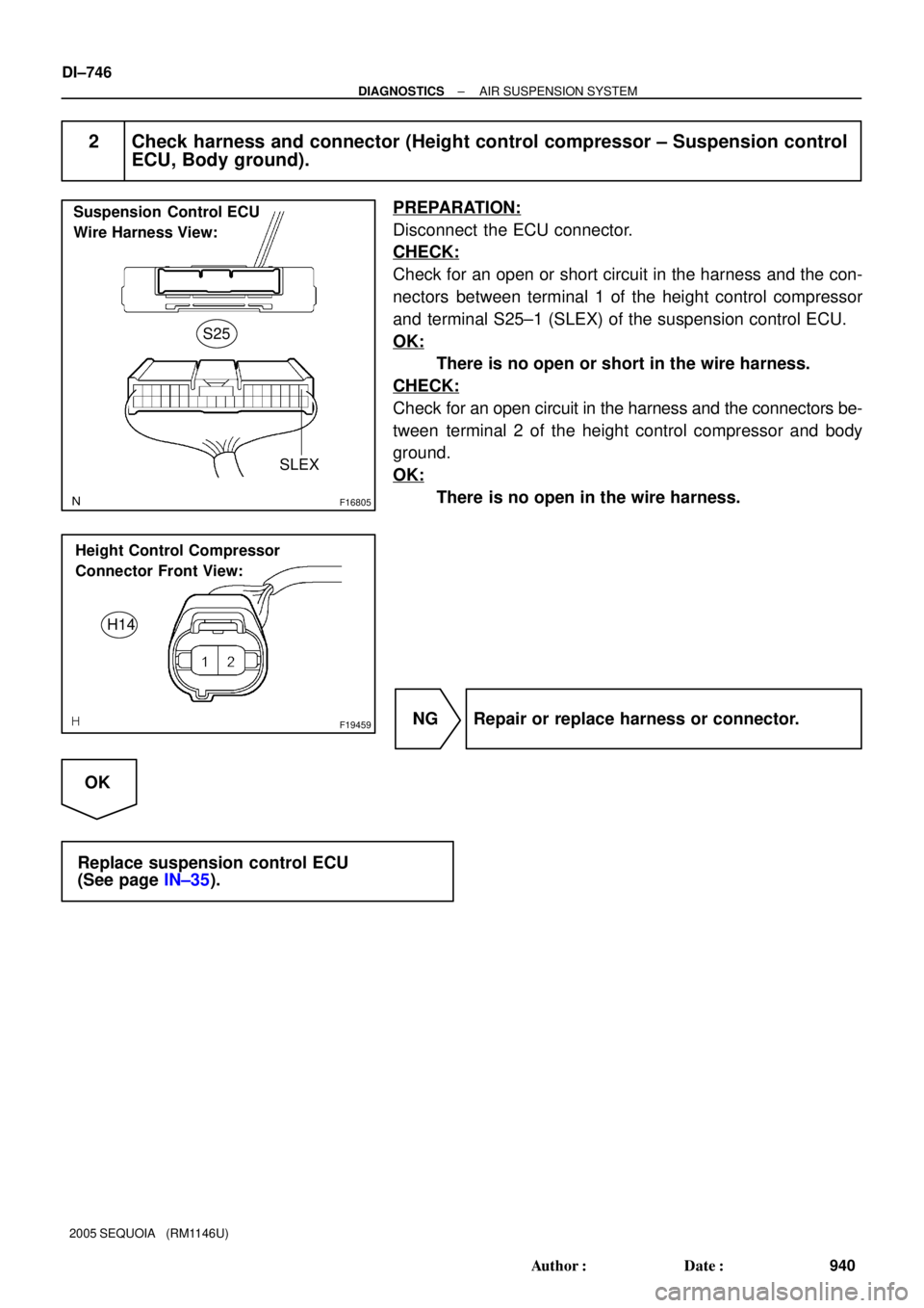
F16805
S25
Suspension Control ECU
Wire Harness View:
SLEX
F19459
Height Control Compressor
Connector Front View:
H14
DI±746
± DIAGNOSTICSAIR SUSPENSION SYSTEM
940 Author�: Date�:
2005 SEQUOIA (RM1146U)
2 Check harness and connector (Height control compressor ± Suspension control
ECU, Body ground).
PREPARATION:
Disconnect the ECU connector.
CHECK:
Check for an open or short circuit in the harness and the con-
nectors between terminal 1 of the height control compressor
and terminal S25±1 (SLEX) of the suspension control ECU.
OK:
There is no open or short in the wire harness.
CHECK:
Check for an open circuit in the harness and the connectors be-
tween terminal 2 of the height control compressor and body
ground.
OK:
There is no open in the wire harness.
NG Repair or replace harness or connector.
OK
Replace suspension control ECU
(See page IN±35).
Page 949 of 4323

DTC C1741/41 Air Sus Relay Circuit
CIRCUIT DESCRIPTION
When the ºUPº side of the height control switch is pre")
± DIAGNOSTICSAIR SUSPENSION SYSTEM
DI±747
941 Author�: Date�:
2005 SEQUOIA (RM1146U)
DTC C1741/41 Air Sus Relay Circuit
CIRCUIT DESCRIPTION
When the ºUPº side of the height control switch is pressed, a signal is sent from terminal RC of the suspen-
sion control ECU to the AIR SUS relay to turn it on.
As a result, the current flows to the AIR SUS relay coil, closing the relay contact, and then the battery positive
voltage is applied to the compressor, which causes the compressed air to raise the vehicle height.
DTC No.DTC Detecting ConditionTrouble Area
C1741/41
Either of the following conditions is detected:
1. With the AIR SUS relay inactivated, an open signal of the
AIR SUS relay is detected for 1 sec. or more.
2. With the AIR SUS relay activated, a short signal of the AIR
SUS relay is detected 8 times successively.
�AIR SUS relay
�AIR SUS relay circuit
�Suspension control ECU
HINT:
Once the ECU stores DTC C1741/41 in the memory, the vehicle height control is suspended until a normal
signal is input to the ECU from the AIR SUS relay. However, the control resumes if the ignition switch is turned
OFF, and then turned ON again.
DIDDT±01
Page 950 of 4323
F19443
Height Control
Compressor
H131
Engine Room R/B No. 2
G±Y AIR SUS Relay
Battery J28
J/C W
BM21
IC48
IA121
WWW
2
22
2 3
25
1W
9B
5
W±B
J8
J/C
AAW±B
1K12
1F9
A W±B
IESuspension
Control
ECU
IA125
G±Y
S255
RC F10
Fusible Link Block
ALT
Instrument
Panel J/BAIR SUS DI±748
± DIAGNOSTICSAIR SUSPENSION SYSTEM
942 Author�: Date�:
2005 SEQUOIA (RM1146U)
WIRING DIAGRAM
Page 954 of 4323

DTC C1742/42 Height Control Compressor Circuit
CIRCUIT DESCRIPTION
When the ºUPº side of the height control i")
DI±752
± DIAGNOSTICSAIR SUSPENSION SYSTEM
946 Author�: Date�:
2005 SEQUOIA (RM1146U)
DTC C1742/42 Height Control Compressor Circuit
CIRCUIT DESCRIPTION
When the ºUPº side of the height control is pressed, a signal is sent from terminal RC of the suspension con-
trol ECU to switch the AIR SUS relay ON. As a result, the relay contacts close and the compressor motor
turns on, producing compressed air.
The suspension control ECU detects the amount of current flow to the compressor motor by means of the
differences in potential at terminals RM+ and RM± of the suspension control ECU. In this way, the suspen-
sion control ECU monitors the compressor circuit for abnormalities.
DTC No.DTC Detecting ConditionTrouble Area
C1742/42
With the AIR SUS relay activated, a lock, open or short signal
of the height control compressor motor is detected for 4 sec. or
more.�Height control compressor assy
�Height control compressor circuit
�Suspension control ECU
HINT:
Once the ECU stores DTC C1742/42 in the memory, the vehicle height control is not carried out until the
normal signal is input to the ECU from the compressor motor. However, the control automatically resumes
approx. 70 min. after the ignition switch is turned ON.
DIDDU±01
Page 955 of 4323
F19444
Height Control Compressor
(Compressor/Height Control Dryer)
H133
Engine Room R/B No. 2
W±B
Battery J28
J/CR±L
BM23
IN115
S2520
2
3
25
1W
9B
5
J8
J/C
AAW±B
1K12
1F9
A W±B
IESuspension
Control
ECU
RC F10
Fusible Link Block
AIR SUS
Instrument
Panel J/BRM+ R±L R±L
H134
BR±Y
BM24
IA121S2521
BR±Y BR±Y
RM±
AIR SUS Relay H131
W
BM21
IC48
WW W
22
2 S255
G±Y IN16
IA125
G±Y
BJ H132
BM22
W±B
AJ19
J/C W±BALT
± DIAGNOSTICSAIR SUSPENSION SYSTEM
DI±753
947 Author�: Date�:
2005 SEQUOIA (RM1146U)
WIRING DIAGRAM
Page 956 of 4323
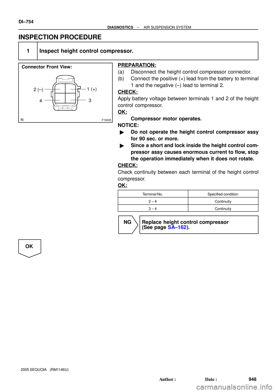
F19435
1 (+)
2 (±)
Connector Front View:
43
DI±754
± DIAGNOSTICSAIR SUSPENSION SYSTEM
948 Author�: Date�:
2005 SEQUOIA (RM1146U)
INSPECTION PROCEDURE
1 Inspect height control compressor.
PREPARATION:
(a) Disconnect the height control compressor connector.
(b) Connect the positive (+) lead from the battery to terminal
1 and the negative (±) lead to terminal 2.
CHECK:
Apply battery voltage between terminals 1 and 2 of the height
control compressor.
OK:
Compressor motor operates.
NOTICE:
�Do not operate the height control compressor assy
for 90 sec. or more.
�Since a short and lock inside the height control com-
pressor assy causes enormous current to flow, stop
the operation immediately when it does not rotate.
CHECK:
Check continuity between each terminal of the height control
compressor.
OK:
Terminal No.Specified condition
2 ± 4Continuity
3 ± 4Continuity
NG Replace height control compressor
(See page SA±162).
OK
Page 957 of 4323
F16805
Suspension Control ECU
Wire Harness View:
S25
RM+
RM±
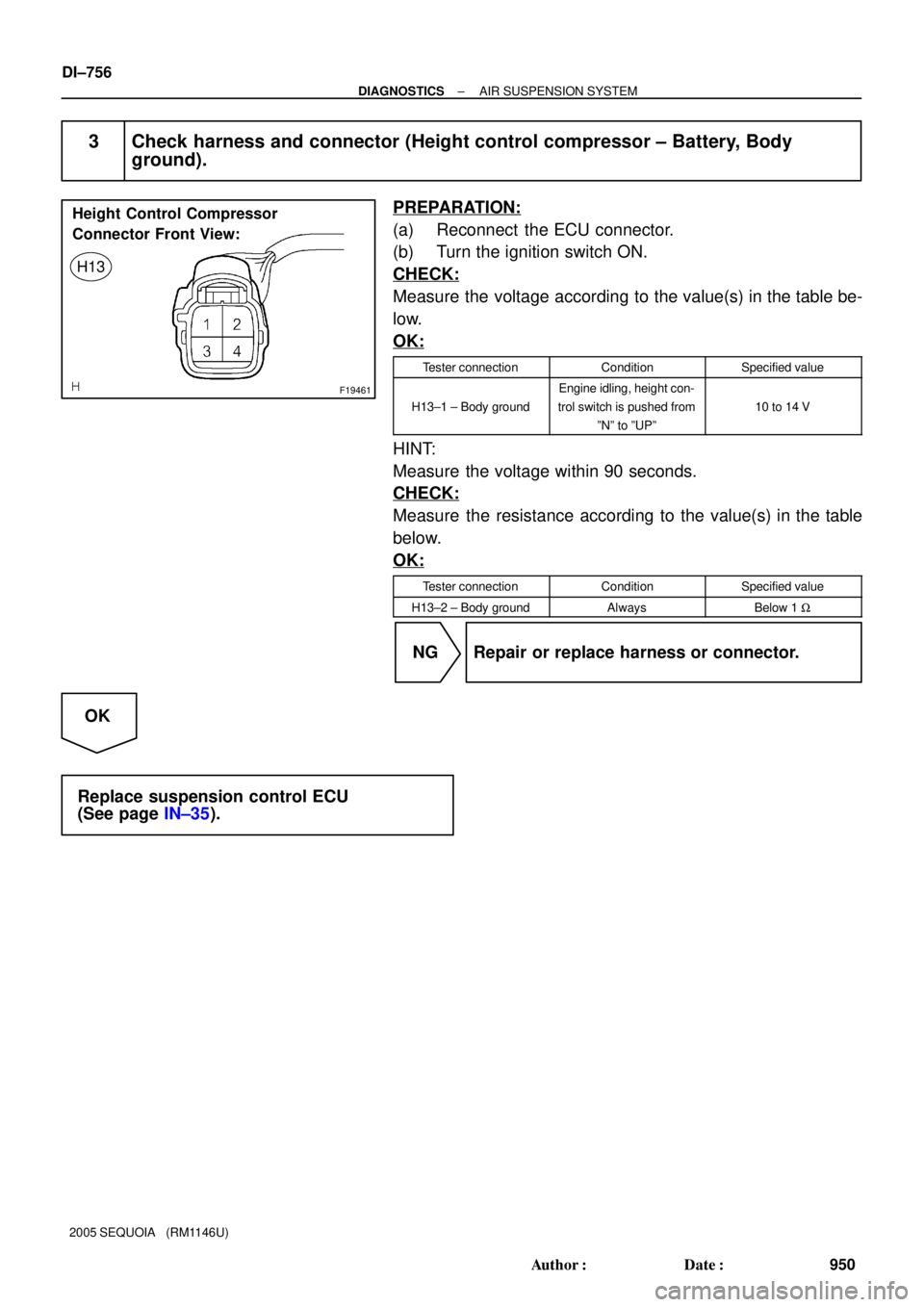
F19461
Height Control Compressor
Connector Front View:
H13
± DIAGNOSTICSAIR SUSPENSION SYSTEM
DI±755
949 Author�: Date�:
2005 SEQUOIA (RM1146U)
2 Check harness and connector (height control compressor ± Suspension control
ECU).
PREPARATION:
Disconnect the ECU connector.
CHECK:
Check for an open or short circuit in the harness and the con-
nector between terminals 3 and 4 of the height control compres-
sor and terminals S25±20 (RM+) and S25±21 (RM±) of the sus-
pension control ECU.
OK:
There is no open or short in the wire harness.
NG Repair or replace harness or connector.
OK
Page 958 of 4323
F19461
Height Control Compressor
Connector Front View:
H13
DI±756
± DIAGNOSTICSAIR SUSPENSION SYSTEM
950 Author�: Date�:
2005 SEQUOIA (RM1146U)
3 Check harness and connector (Height control compressor ± Battery, Body
ground).
PREPARATION:
(a) Reconnect the ECU connector.
(b) Turn the ignition switch ON.
CHECK:
Measure the voltage according to the value(s) in the table be-
low.
OK:
Tester connectionConditionSpecified value
H13±1 ± Body ground
Engine idling, height con-
trol switch is pushed from
ºNº to ºUPº
10 to 14 V
HINT:
Measure the voltage within 90 seconds.
CHECK:
Measure the resistance according to the value(s) in the table
below.
OK:
Tester connectionConditionSpecified value
H13±2 ± Body groundAlwaysBelow 1 W
NG Repair or replace harness or connector.
OK
Replace suspension control ECU
(See page IN±35).


H133
Engine Room R/B No. 2
W±B
Battery J28
J/CR±L
BM23
IN115
S2520
2
3
25
1W
9B
5
J8
J/C
AAW±B
1K12
1F9
A W±B
IESuspension
Contro")