Page 710 of 4323
I08467
LOCKACC
ON
START
DI±508
± DIAGNOSTICSENGINE
702 Author�: Date�:
2005 SEQUOIA (RM1146U)
9 Check ignition switch.
PREPARATION:
(a) Remove the lower finish panel.
(b) Disconnect the ignition switch connector.
CHECK:
Check resistance between terminals.
OK:
Standard:
Switch PositionTerminal ConditionSpecified Condition
LOCKAlways10 kW or more
ACC1 ± 3Below 1 W
ON1 ± 2 ± 3
5 ± 6Below 1 W
START1 ± 2
4 ± 5 ± 6Below 1 W
NG Replace ignition switch.
OK
Check for open in harness and connector be-
tween ECM and ignition switch, ignition
switch and battery (See page IN±35).
Page 711 of 4323
± DIAGNOSTICSENGINE
DI±509
703 Author�: Date�:
2005 SEQUOIA (RM1146U)
Fuel Pump Control Circuit
CIRCUIT DESCRIPTION
Refer to DTC P0230 on page DI±179.
WIRING DIAGRAM
Refer to DTC P0230 on page DI±179.
INSPECTION PROCEDURE
1 Check fuel pump operation (See page SF±7).
OK Go to step 8.
NG
2 Connect hand±held tester, and check operation of fuel pump relay.
PREPARATION:
(a) Connect the hand±held tester to the DLC3.
(b) Turn the ignition switch ON and push the hand±held tester main switch ON.
(c) Enter the following menu: DIAGNOSIS / ENHANCED OBD II / ACTIVE TEST / FUEL PUMP SPD.
CHECK:
Check the operation of the fuel pump relay when it is switched ON and OFF by the hand±held tester.
OK:
Operating noise can be heard from the relay.
OK Go to step 4.
NG
DID8L±01
Page 712 of 4323
A21024
A19288
DI±510
± DIAGNOSTICSENGINE
704 Author�: Date�:
2005 SEQUOIA (RM1146U)
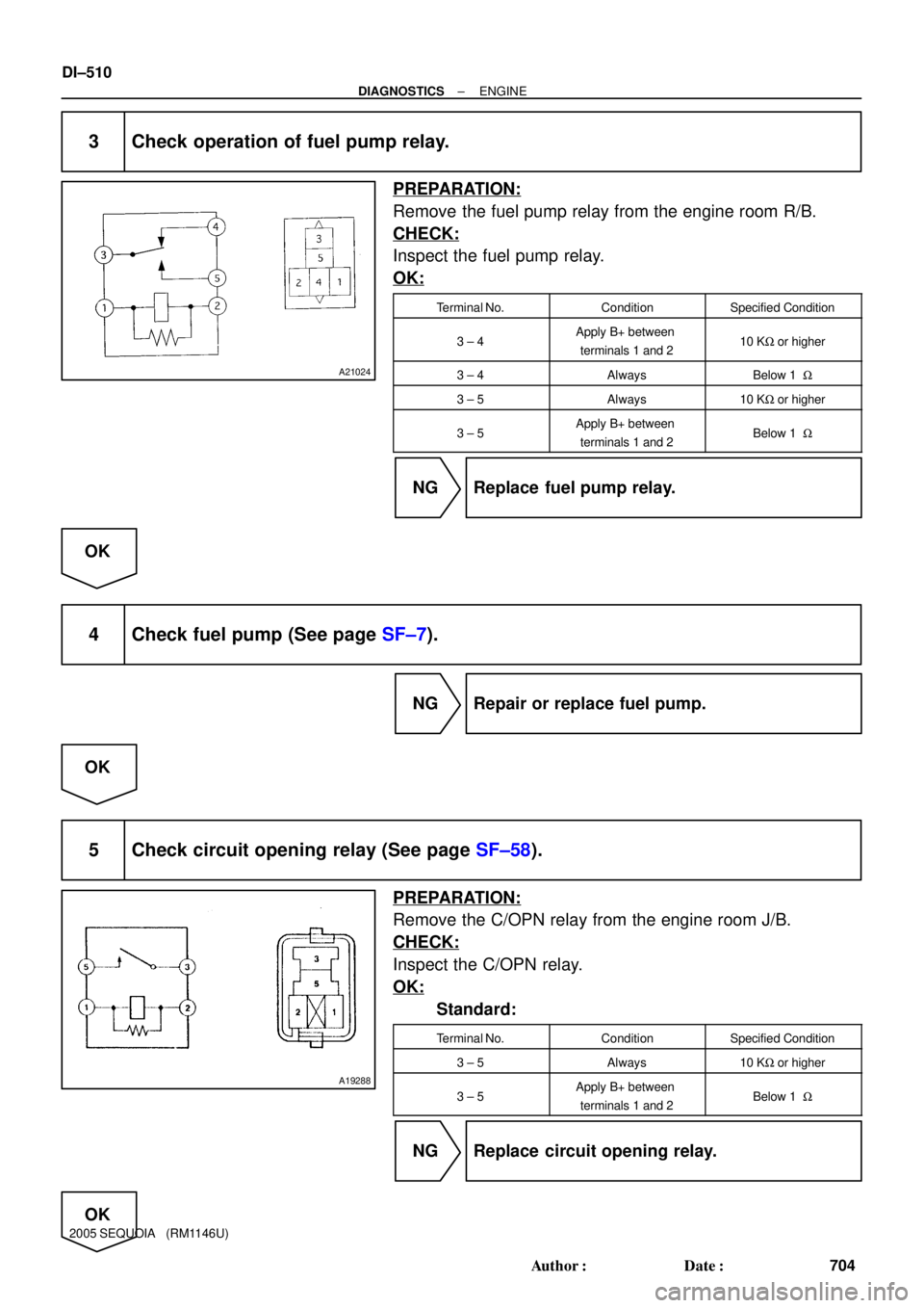
3 Check operation of fuel pump relay.
PREPARATION:
Remove the fuel pump relay from the engine room R/B.
CHECK:
Inspect the fuel pump relay.
OK:
Terminal No.ConditionSpecified Condition
3 ± 4Apply B+ between
terminals 1 and 210 KW or higher
3 ± 4AlwaysBelow 1 W
3 ± 5Always10 KW or higher
3 ± 5Apply B+ between
terminals 1 and 2Below 1 W
NG Replace fuel pump relay.
OK
4 Check fuel pump (See page SF±7).
NG Repair or replace fuel pump.
OK
5 Check circuit opening relay (See page SF±58).
PREPARATION:
Remove the C/OPN relay from the engine room J/B.
CHECK:
Inspect the C/OPN relay.
OK:
Standard:
Terminal No.ConditionSpecified Condition
3 ± 5Always10 KW or higher
3 ± 5Apply B+ between
terminals 1 and 2Below 1 W
NG Replace circuit opening relay.
OK
Page 713 of 4323
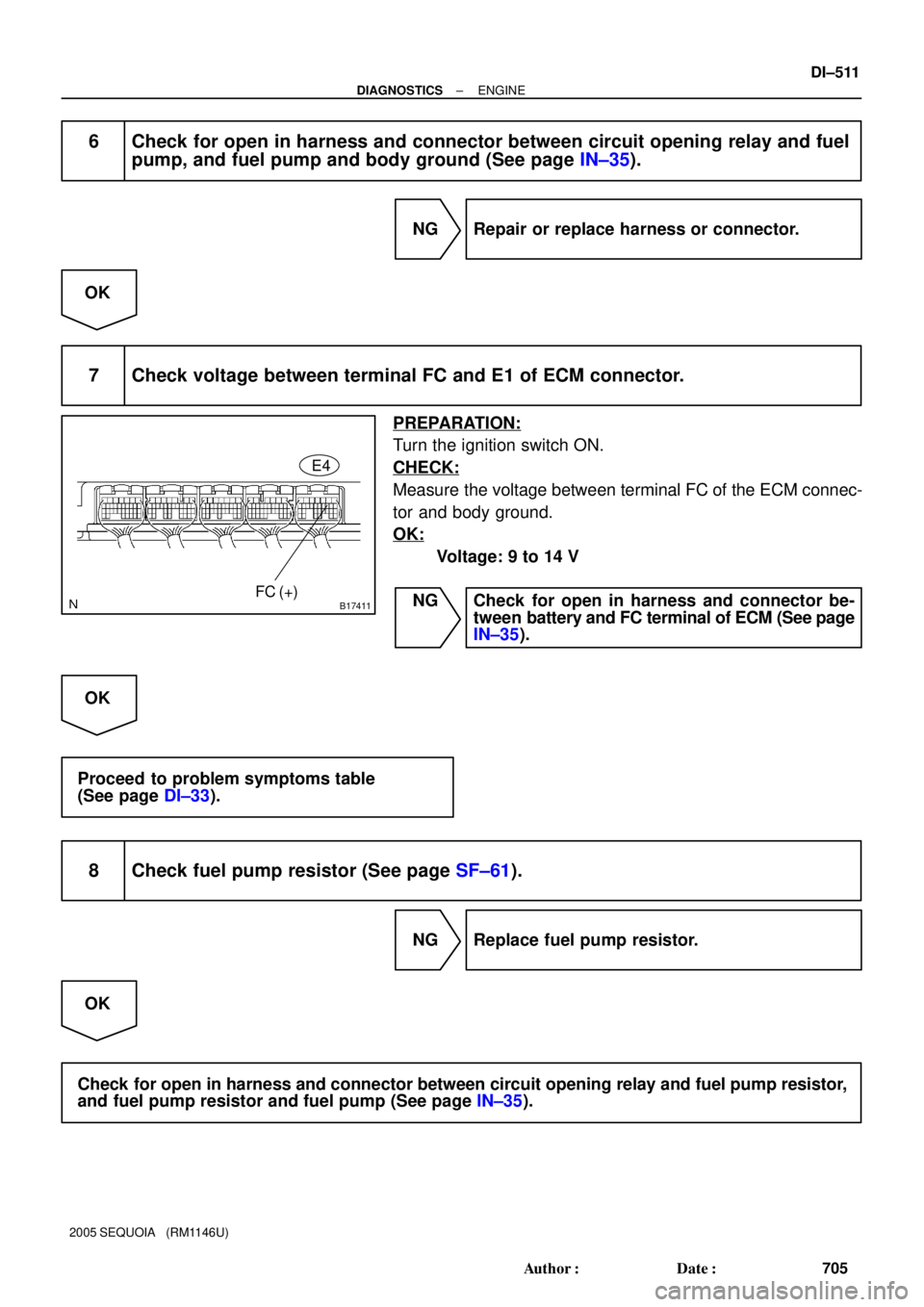
B17411FC (+)E4
± DIAGNOSTICSENGINE
DI±511
705 Author�: Date�:
2005 SEQUOIA (RM1146U)
6 Check for open in harness and connector between circuit opening relay and fuel
pump, and fuel pump and body ground (See page IN±35).
NG Repair or replace harness or connector.
OK
7 Check voltage between terminal FC and E1 of ECM connector.
PREPARATION:
Turn the ignition switch ON.
CHECK:
Measure the voltage between terminal FC of the ECM connec-
tor and body ground.
OK:
Voltage: 9 to 14 V
NG Check for open in harness and connector be-
tween battery and FC terminal of ECM (See page
IN±35).
OK
Proceed to problem symptoms table
(See page DI±33).
8 Check fuel pump resistor (See page SF±61).
NG Replace fuel pump resistor.
OK
Check for open in harness and connector between circuit opening relay and fuel pump resistor,
and fuel pump resistor and fuel pump (See page IN±35).
Page 714 of 4323
A21044
Engine
Room
R/BR±B
7ECM
W
E4 11
C8
C10 12
B
R±L15 2
2
Battery7
6I18
Ignition
Switch
41D
1G 6
B±R R
GAUGE
Combination
Meter Malfunction
Indicator
Lamp AM2
IG2 AM2
DI±512
± DIAGNOSTICSENGINE
706 Author�: Date�:
2005 SEQUOIA (RM1146U)
MIL Circuit
CIRCUIT DESCRIPTION
If the ECM detects a trouble, the MIL lights up. At this time, the ECM records a DTC in the memory.
WIRING DIAGRAM
DICFG±02
Page 715 of 4323
B17418W E5
± DIAGNOSTICSENGINE
DI±513
707 Author�: Date�:
2005 SEQUOIA (RM1146U)
INSPECTION PROCEDURE
HINT:
Troubleshoot each trouble symptom in accordance with the chart below.
MIL remains onStart inspection from step 1
MIL does not light upStart inspection from step 3
1 Clear DTC.
PREPARATION:
(a) Connect the hand±held tester to the DLC3.
(b) Turn the ignition switch ON and push the hand±held tester main switch ON.
(c) Read the DTC (See page DI±43).
(d) Clear the DTC (See page DI±43).
CHECK:
(a) Check that MIL does not light up.
OK:
Standard: MIL does not light up
OK Repair circuit indicated by output code
(See page DI±58).
NG
2 Check Harness and connector (Check for short in wire harness).
PREPARATION:
(a) Disconnect the E4 ECM connector.
(b) Turn the ignition switch ON.
CHECK:
(a) Check that MIL does not light up.
OK:
Standard: MIL does not light up
OK Replace ECM (See page SF±80).
NG
Check and repair harness and connector be-
tween combination meter and ECM.
Page 716 of 4323
DI±514
± DIAGNOSTICSENGINE
708 Author�: Date�:
2005 SEQUOIA (RM1146U)
3 Check that MIL lights up.
CHECK:
Check that MIL lights up when turning the ignition switch ON.
OK:
Standard: MIL lights up
OK System OK.
NG
4 Inspect combination meter assy (MIL circuit).
See the combination meter troubleshooting on page BE±55.
NG Repair or replace bulb or combination meter as-
sembly.
OK
Check and repair harness and connector be-
tween combination meter and ECM.
Page 719 of 4323

TOYOTA PART AND SYSTEM NAME LIST
This reference list indicates the part names used in this manual al")
DIDIJ±01
± DIAGNOSTICSAUTOMATIC TRANSMISSION
DI±517
711 Author�: Date�:
2005 SEQUOIA (RM1146U)
TOYOTA PART AND SYSTEM NAME LIST
This reference list indicates the part names used in this manual along with their definitions.
Part and system nameDefinition
Toyota HCAC system, Hydrocarbon adsorptive Catalyst
(HCAC) system, HC adsorptive three±way catalystHC adsorptive three±way catalytic converter
Variable Valve Timing sensor, VVT sensorCamshaft position sensor
Variable valve timing system, VVT systemCamshaft timing control system
Camshaft timing oil control valve, Oil control valve OCV,
VVT, VSVCamshaft timing oil control valve
Variable timing and lift, VVTLCamshaft timing and lift control
Crankshaft position sensor ºAºCrankshaft position sensor
Engine speed sensorCrankshaft position sensor
THAIntake air temperature
Knock control moduleEngine knock control module
Knock sensorEngine knock sensor
Mass or volume air flow circuitMass air flow sensor circuit
Vacuum sensorManifold air pressure sensor
Internal control module, Control module, Engine control
ECU, PCMPower train control module
FC idleDeceleration fuel cut
Idle air control valveIdle speed control
VSV for CCV, Canister close valve VSV for canister controlEvaporative emissions canister vent valve
VSV for EVAP, Vacuum switching valve assembly No. 1,
EVAP VAV, Purge VSVEvaporative emissions canister purge valve
VSV for pressure switching valve, Bypass VSVEvaporative emission pressure switching valve
Vapor pressure sensor, EVAP pressure sensor, Evaporative
emission control system pressure sensorFuel tank pressure sensor
Charcoal canisterEvaporative emissions canister
ORVR systemOn±board refueling vapor recovery system
Intake manifold runner controlIntake manifold tuning system
Intake manifold runner valve, IMRV, IACV (runner valve)Intake manifold tuning valve
Intake control VSVIntake manifold tuning solenoid valve
AFSAir fuel ratio sensor
O2 sensorHeater oxygen sensor
Oxygen sensor pumping current circuitOxygen sensor output signal
Oxygen sensor reference ground circuitOxygen sensor signal ground
Accel position sensorAccelerator pedal position sensor
Throttle actuator control motor, Actuator control motor, Elec-
tronic throttle motor, Throttle control motorElectronic throttle actuator
Electronic throttle control system, Throttle actuator control
systemElectronic throttle control system
Throttle/pedal position sensor, Throttle/pedal position switch,
Throttle position sensor/switchThrottle position sensor
Turbo press sensorTurbocharger pressure sensor
Turbo VSVTurbocharger pressure control solenoid valve
P/S pressure switchPower±steering pressure switch
VSV for ACMActive control engine mount
Speed sensor, Vehicle speed sensor ºAº, Speed sensor for
skid control ECUVehicle speed sensor
ATF temperature sensor, Trans. fluid temp. sensor, ATF
temperature sensor ºAºTransmission fluid temperature sensor
Electronic controlled automatic transmission, ECTElectronically controlled automatic
Intermediate shaft speed sensor ºAºCounter gear speed sensor