Page 678 of 4323
A23506
ON
0.02 inch Orifice High±flow
3/5
ONON
Purge VSV
Vent Valve
Vacuum Pump
EVAP Pressure
Positive
Negative
Steps
(Reference)TimeON: Open
OFF: Closed
OFF: Vent ON: Closed
Leak Pressure 0.02 inch
Standard
2/5
Vacuum Pump Stuck OFF
Within 15 minutes
DI±476
± DIAGNOSTICSENGINE
670 Author�: Date�:
2005 SEQUOIA (RM1146U)
11 Perform EVAP system step 3/5 check.
(a) Check the EVAP pressure in step 3/5.
Result:
DTCs*Test ResultsSuspected Trouble AreasProceed To
'EVAP pressure less than [0.02 inch leak pressure
standard x 0.2]0.02 inch orifice high±flowA
'EVAP pressure more than [0.02 inch leak pressure
standard x 0.2]Vacuum pump stuck OFFB
*: The DTCs relating to the EVAP system displayed on a hand±held tester when checking.
HINT:
The 0.02 inch leak pressure standard is the value determined in step 2/5.
A Go to step 30.
B Go to step 23.
Page 679 of 4323
B17420
HosePurge VSV
± DIAGNOSTICSENGINE
DI±477
671 Author�: Date�:
2005 SEQUOIA (RM1146U)
12 Perform active test of purge VSV.
PREPARATION:
(a) On the hand±held tester, select the following menu items:
DIAGNOSIS / ENHANCED OBD II/ ACTIVE TEST /
EVAP VSV.
(b) Disconnect the hose (connected to the canister) from the
purge VSV.
(c) Start the engine.
CHECK:
(a) On the tester, turn off the purge VSV (EVAP VSV: OFF).
(b) Use your finger to confirm that the purge VSV has no suc-
tion.
(c) Using the tester, turn on the purge VSV (EVAP VSV: ON).
(d) Use your finger to confirm that the purge VSV has suction.
RESULT:
Test ResultsSuspected Trouble AreasProceed To
No suction when purge VSV turned OFF, and suction applied
when tuned ONPurge VSV normalA
Suction applied when purge VSV turned OFFPurge VSV stuck openB
No suction when purge VSV turned ON
�Purge VSV stuck closed
�Problems with EVAP hose between purge VSV and throttle
body
C
B Go to step 14.
C Go to step 15.
A
Page 680 of 4323

13 Check fuel tank cap.
CHECK:
(a) Check that the fuel tank cap is correctly installed.
(b) Confirm that the fuel tank cap is")
DI±478
± DIAGNOSTICSENGINE
672 Author�: Date�:
2005 SEQUOIA (RM1146U)
13 Check fuel tank cap.
CHECK:
(a) Check that the fuel tank cap is correctly installed.
(b) Confirm that the fuel tank cap is tightened until a few click sounds are heard.
HINT:
If an EVAP tester is available, check the fuel tank cap using the tester.
(1) Remove the fuel tank cap and install it onto a fuel tank cap adaptor.
(2) Connect an EVAP tester pump hose to the adaptor, and pressurize to 3.2 to 3.7 kPa (24 to 28
mmHg) using an EVAP tester pump.
(3) Seal the adaptor and wait for 2 minutes.
(4) Check the pressure. If the pressure is 2 kPa (15 mmHg) or more, the fuel tank cap is normal.
(5) Reinstall the fuel tank cap.
PREPARATION:
Test ResultsSuspected Trouble AreasProceed To
Fuel tank cap correctly installed'A
Fuel tank cap loose
�Fuel tank cap improperly installed
�Defective fuel tank cap
�Fuel tank cap does not meet OEM specifications
B
No fuel tank cap'C
A Go to step 29.
B Go to step 27.
C Go to step 28.
Page 681 of 4323
B17419
HosePurge VSV
B17420
HosePurge VSV
± DIAGNOSTICSENGINE
DI±479
673 Author�: Date�:
2005 SEQUOIA (RM1146U)
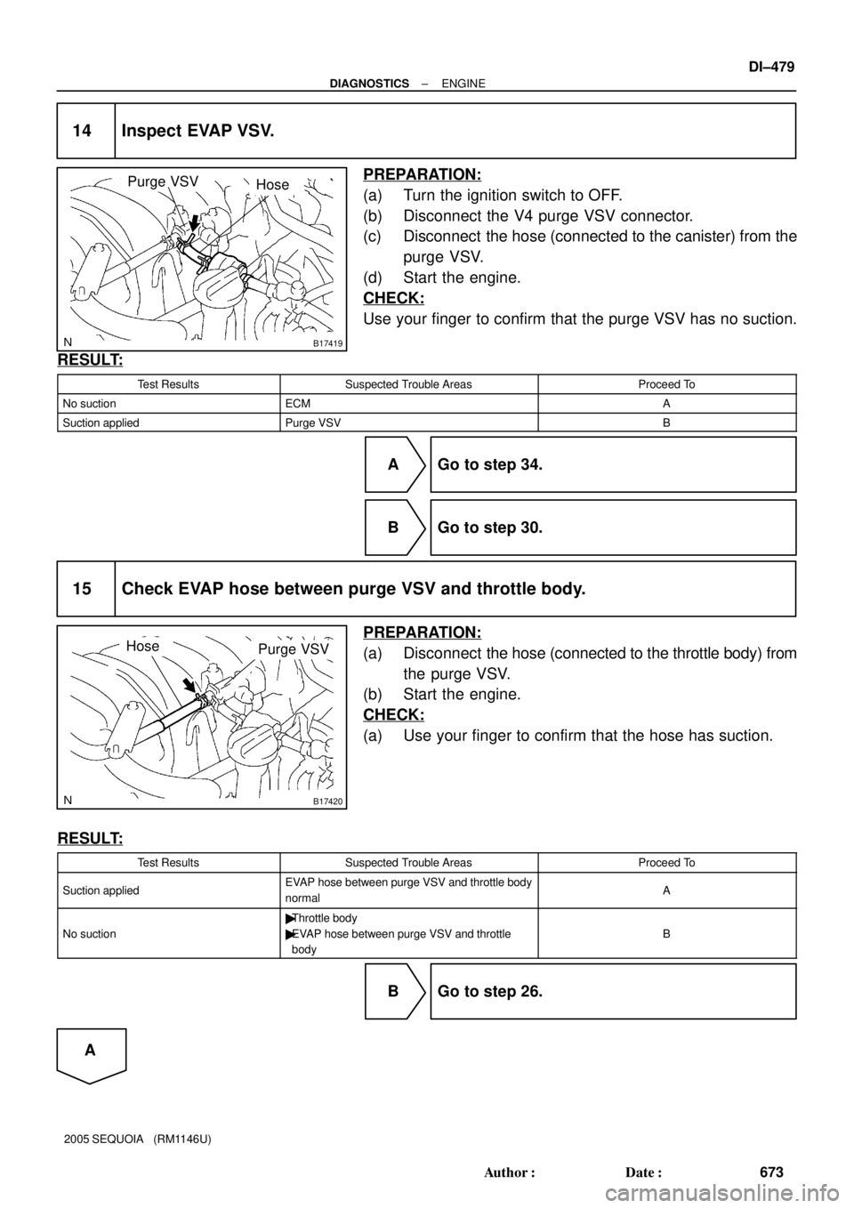
14 Inspect EVAP VSV.
PREPARATION:
(a) Turn the ignition switch to OFF.
(b) Disconnect the V4 purge VSV connector.
(c) Disconnect the hose (connected to the canister) from the
purge VSV.
(d) Start the engine.
CHECK:
Use your finger to confirm that the purge VSV has no suction.
RESULT:
Test ResultsSuspected Trouble AreasProceed To
No suctionECMA
Suction appliedPurge VSVB
A Go to step 34.
B Go to step 30.
15 Check EVAP hose between purge VSV and throttle body.
PREPARATION:
(a) Disconnect the hose (connected to the throttle body) from
the purge VSV.
(b) Start the engine.
CHECK:
(a) Use your finger to confirm that the hose has suction.
RESULT:
Test ResultsSuspected Trouble AreasProceed To
Suction appliedEVAP hose between purge VSV and throttle body
normalA
No suction
�Throttle body
�EVAP hose between purge VSV and throttle
body
B
B Go to step 26.
A
Page 682 of 4323
B02272
Battery
Air
B17440
Wire Harness Side:
Purge VSV Connector
V4
Front View
DI±480
± DIAGNOSTICSENGINE
674 Author�: Date�:
2005 SEQUOIA (RM1146U)
16 Inspect EVAP VSV.
PREPARATION:
(a) Remove the purge VSV.
(b) Apply battery voltage to the terminals of the purge VSV.
CHECK:
Using an air gun, confirm that air flows from port A to port B.
RESULT:
Test ResultsSuspected Trouble AreasProceed To
Suction appliedEVAP hose between purge VSV and throttle body
normalA
No suction
�Throttle body
�EVAP hose between purge VSV and throttle
body
B
B Go to step 31.
A
17 Measure purge VSV terminal voltage.
PREPARATION:
(a) Disconnect the V4 purge VSV connector.
(b) Turn the ignition switch to ON.
CHECK:
(a) Measure the voltage between terminal 1 of the purge VSV
connector and the body ground.
RESULT:
Test ResultsSuspected Trouble AreasProceed To
Between 11 V and 14 VNormalA
Other than result aboveWire harness or connectors between purge VSV
and ECMB
B Go to step 32.
A
Page 683 of 4323

18 Check for open and short circuit in")
B17412PRG
E8
B17440
Wire Harness Side:
Purge VSV Connector
V4
Front View
B17411VPMP
E4
± DIAGNOSTICSENGINE
DI±481
675 Author�: Date�:
2005 SEQUOIA (RM1146U)
18 Check for open and short circuit in harness and connector between purge VSV
and ECM.
PREPARATION:
Disconnect the E8 ECM connector and the V4 purge VSV con-
nector.
CHECK:
Check the resistance.
OK:
Standard:
Tester ConnectionsSpecified Conditions
E8±34 (PRG) ± V4±1Below 1 W
E8±34 (PRG) ± Body ground10 kW or higher
V4±1 ± Body ground10 kW or higher
OK Go to step 35.
NG Go to step 32.
19 Perform active test for vent valve.
PREPARATION:
(a) Turn the ignition switch to ON.
(b) On the hand±held tester, select the following menu items:
DIAGNOSIS/ ENHANCED OBD II/ ACTIVE TEST/ VENT
VALVE (ALONE).
CHECK:
Measure the voltage between terminal VPMP of the ECM con-
nector and the body ground when the vent valve is turned ON
(close) and OFF (vent) using the tester.
RESULT:
Test ResultsSuspected Trouble AreasProceed To
Between 9 V and 14 V when OFF
Below 3 V when ONVent valveA
Below 3 V when OFF and ONECMB
A Go to step 22.
B Go to step 35.
Page 684 of 4323
B17411VPMP
E4
DI±482
± DIAGNOSTICSENGINE
676 Author�: Date�:
2005 SEQUOIA (RM1146U)
20 Perform active test for vent valve.
PREPARATION:
(a) Turn the ignition switch to ON.
(b) On the hand±held tester, select the following menu items:
DIAGNOSIS/ ENHANCED OBD II/ ACTIVE TEST/ VENT
VALVE (ALONE).
CHECK:
Measure the voltage between terminal VPMP of the ECM con-
nector and the body ground when the vent valve is turned ON
(close) and OFF (vent) using the tester.
RESULT:
Test ResultsSuspected Trouble AreasProceed To
Below 3 V when OFF and ONPower source of vent valveA
Between 9 V and 14 V when OFF
Below 3 V when ONVent valveB
Between 9 V and 14 V when OFF and ONECMC
B Go to step 24.
C Go to step 35.
A
Page 685 of 4323
A23446
L5
A23508
Wire Harness Side:
Canister Connector
Front View
L5
± DIAGNOSTICSENGINE
DI±483
677 Author�: Date�:
2005 SEQUOIA (RM1146U)
21 Inspect pump module power source circuit.
PREPARATION:
(a) Turn the ignition switch to OFF.
(b) Disconnect the L5 canister connector.
(c) Turn the ignition switch to ON.
CHECK:
Measure the voltage between terminal 9 of the canister connec-
tor and the body ground.
RESULT:
Test ResultsSuspected Trouble AreasProceed To
Between 9 V and 14 VNormalA
Between 0 V and 3 VPower source wire harness of vent valveB
B Go to step 32.
A
TimeON: Open
OFF: Closed
OFF: Vent ON: Closed
Leak Pressure 0.02 inch")