Page 694 of 4323
A23517
Key±off Monitor
Purge VSV
Vent Valve
Atmosphere (0 kPa)
Criterion 1 (±1.2 kPa)
Criterion 5 (±4.3 kPa)
Elapsed Time (Seconds)
104EVAP Pressure
(Reference) PumpMonitor Start
ON (Open)
ON (Close)
ON
A
BC
60D
GWithin 720 Criterion 2 (Criterion 4 x 0.2)
Criterion 3 (0.3 kPa)
Criterion 4EF
Criterion 6 (0.3 kPa)
1060
Purge Flow Monitor
Sequence
Purge VSV
Vent Valve
Criterion 7 (0.1 kPa)
EVAP Pressure
(Reference)
Criterion 8 (1kPa)If pressure change in sequence 1 is
greater than criterion 7, purge flow moni-
tor is completed (functioning normally). ON (Close) 12
ON (Open)
If pressure change in sequence 1 is
smaller than criterion 7, sequence 2 is
run.
If pressure change in sequence 2 is
smaller than criterion 8, purge flow is in-
sufficient.
DI±492
± DIAGNOSTICSENGINE
686 Author�: Date�:
2005 SEQUOIA (RM1146U)
Page 695 of 4323
± DIAGNOSTICSENGINE
DI±493
687 Author�: Date�:
2005 SEQUOIA (RM1146U)
ECM Power Source Circuit
CIRCUIT DESCRIPTION
When the ignition switch is turned ON, battery positive voltage is applied to terminal IGSW of the ECM and
the EFI relay control circuit in the ECM sends a signal to terminal MREL of the ECM switching on the EFI
relay.
This signal causes current to flow to the coil, closing the contacts of the EFI relay and supplying power to
terminal +B of the ECM.
DID8K±01
Page 696 of 4323
A23555
F10
Fusible
Link
Block9
+B
BatteryE1 1
8
1 E4
E6
BR 4D
B±R
67 I18 Ignition SW 2
W±R 1C 1E
1C2
13
BIG2
IA4
B±WECM
Engine Room J/B
EFI Relay
1DIGSW
MREL E4E4 17 IGN1
4E
Instrument Panel J/BSub J/B No. 4
5
AM2 Instrument Panel J/B
1
16 AM21J
2D
2F2C
2H 5
32
IA4J/C
5 4
B14 12 2
J16
A
EB EDD
J5
J/C W±B2H
2B±R
B±WB±R B±R EFI No. 1W±RB±O
B±O DI±494
± DIAGNOSTICSENGINE
688 Author�: Date�:
2005 SEQUOIA (RM1146U)
WIRING DIAGRAM
Page 697 of 4323
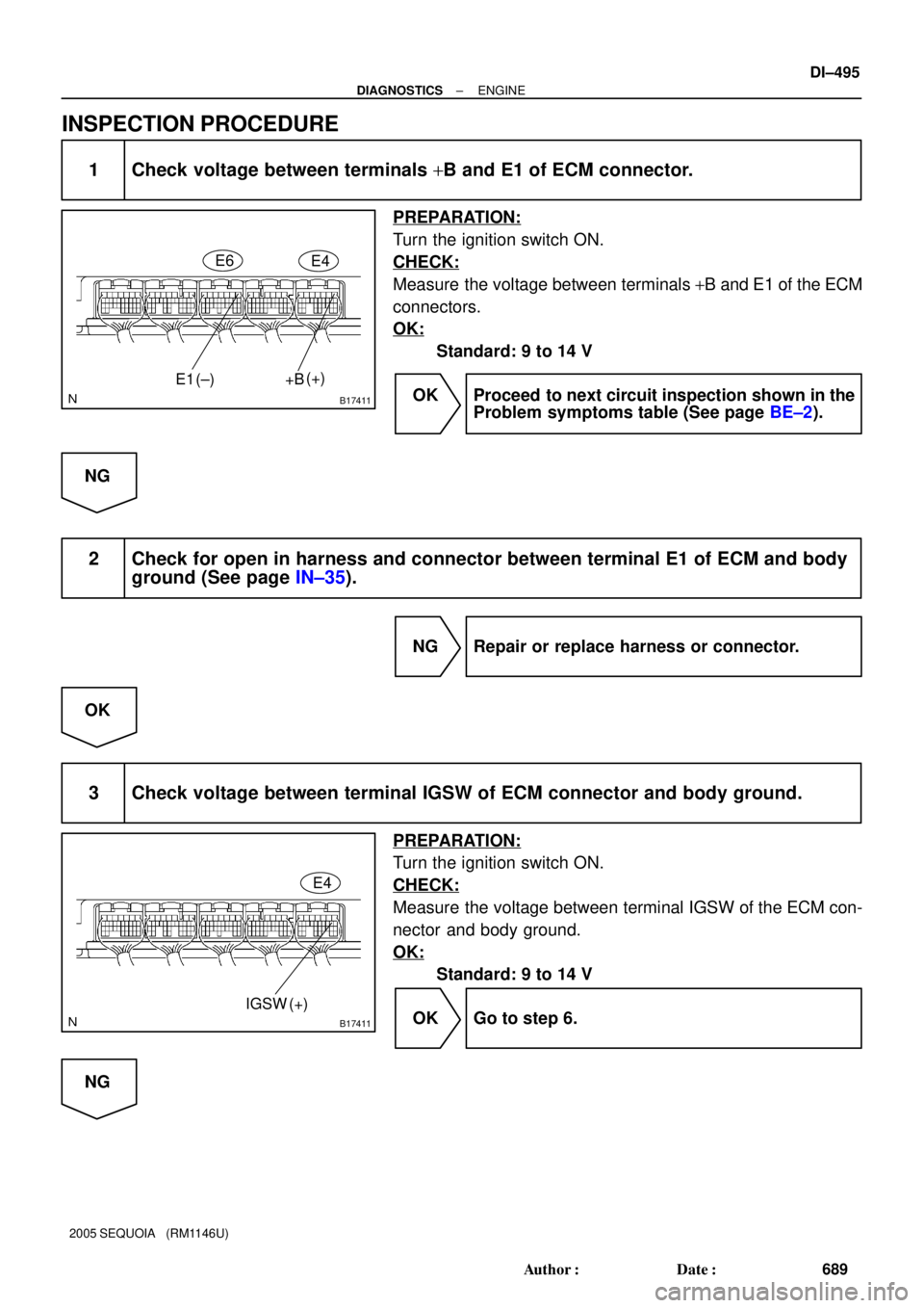
B17411
+B E1(+)
(±)E6
E4
B17411
IGSW (+)E4
± DIAGNOSTICSENGINE
DI±495
689 Author�: Date�:
2005 SEQUOIA (RM1146U)
INSPECTION PROCEDURE
1 Check voltage between terminals +B and E1 of ECM connector.
PREPARATION:
Turn the ignition switch ON.
CHECK:
Measure the voltage between terminals +B and E1 of the ECM
connectors.
OK:
Standard: 9 to 14 V
OK Proceed to next circuit inspection shown in the
Problem symptoms table (See page BE±2).
NG
2 Check for open in harness and connector between terminal E1 of ECM and body
ground (See page IN±35).
NG Repair or replace harness or connector.
OK
3 Check voltage between terminal IGSW of ECM connector and body ground.
PREPARATION:
Turn the ignition switch ON.
CHECK:
Measure the voltage between terminal IGSW of the ECM con-
nector and body ground.
OK:
Standard: 9 to 14 V
OK Go to step 6.
NG
Page 698 of 4323
A21560
IGN1 Instrument
Panel J/B:
I08467
LOCKACC
ON
START
DI±496
± DIAGNOSTICSENGINE
690 Author�: Date�:
2005 SEQUOIA (RM1146U)
4 Check IGN1 fuse.
PREPARATION:
Remove the IGN1 fuse from the instrument panel J/B.
CHECK:
Check the resistance of the IGN1 fuse.
OK:
Below 1 W
NG Check for short in all harness and components
connected to IGN1 fuse.
OK
5 Check ignition switch (See page BE±24).
PREPARATION:
(a) Remove the lower finish panel.
(b) Disconnect the ignition switch connector.
CHECK:
Check resistance between terminals.
OK:
Standard:
Switch PositionTerminal ConditionSpecified Condition
LOCKAlways10 kW or more
ACC1 ± 3Below 1 W
ON1 ± 2 ± 3
5 ± 6Below 1 W
START1 ± 2
4 ± 5 ± 6Below 1 W
NG Replace ignition switch.
OK
Check and repair harness and connector be-
tween IGN fuse and ECM.
Page 699 of 4323
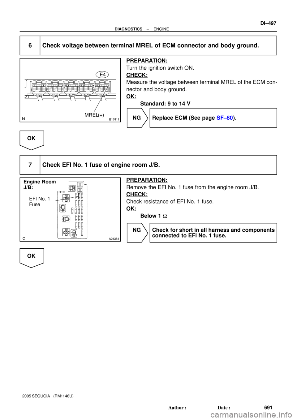
B17411MREL(+)E4
Engine Room
J/B:
A21381
EFI No. 1
Fuse
± DIAGNOSTICSENGINE
DI±497
691 Author�: Date�:
2005 SEQUOIA (RM1146U)
6 Check voltage between terminal MREL of ECM connector and body ground.
PREPARATION:
Turn the ignition switch ON.
CHECK:
Measure the voltage between terminal MREL of the ECM con-
nector and body ground.
OK:
Standard: 9 to 14 V
NG Replace ECM (See page SF±80).
OK
7 Check EFI No. 1 fuse of engine room J/B.
PREPARATION:
Remove the EFI No. 1 fuse from the engine room J/B.
CHECK:
Check resistance of EFI No. 1 fuse.
OK:
Below 1 W
NG Check for short in all harness and components
connected to EFI No. 1 fuse.
OK
Page 700 of 4323
A19288
EFI Relay
B17417
E4
MREL ECM Connector
DI±498
± DIAGNOSTICSENGINE
692 Author�: Date�:
2005 SEQUOIA (RM1146U)
8 Check EFI relay.
PREPARATION:
Remove the EFI relay from the engine room J/B.
CHECK:
Inspect the EFI relay.
OK:
Standard:
Terminal No.ConditionSpecified Condition
3 ± 5Always10 KW or higher
3 ± 5Apply B+ between
terminals 1 and 2Below 1 W
NG Replace EFI relay.
OK
9 Check for open and short in harness and connector between terminal MREL of
ECM and body ground.
PREPARATION:
Disconnect the E4 ECM connector.
CHECK:
Measure the resistance between the wire harness side connec-
tor and body ground.
OK:
Standard:
Tester ConnectionSpecified Condition
MREL (E4±8) ± Body groundBelow 1 W
NG Repair or replace harness or connector.
OK
Check for intermittent problems
(See page DI±11).
Page 701 of 4323
A01995A15196
A15197
IACVIACV closed (VSV: ON)
Intake
Manifold
60°
Throttle valve
opening angle
Engine speed (rpm) 4,700
± DIAGNOSTICSENGINE
DI±499
693 Author�: Date�:
2005 SEQUOIA (RM1146U)
IACV Control Circuit
CIRCUIT DESCRIPTION
This circuit opens and closes the Intake Air Control Valve (IACV) in response to the engine load in order to
increase the intake efficiency (ACIS: Acoustic Control Induction System).
When the engine speed is 4,700 rpm or more and the throttle valve opening angle is 60° or more, the VSV
is OFF, so the is IACV open. All the other times, the ECM turns the VSV ON and closes the IACV.
DIDG0±01

Criterion 1 (±1.2 kPa)
Criterion 5 (±4.3 kPa)
Elapsed Time (Seconds)
104EVAP Pressure
(Reference) PumpMonitor Start
ON (Open)
ON (Clo")