Page 259 of 4323
P0351
(DI±221)
Ignition Coil ºAº Primary/Second-
ary Circuit
�Open or short in IGF 1 and IGT 1 circuit from No. 1 ignition co")
± DIAGNOSTICSENGINE
DI±65
259 Author�: Date�:
2005 SEQUOIA (RM1146U)P0351
(DI±221)
Ignition Coil ºAº Primary/Second-
ary Circuit
�Open or short in IGF 1 and IGT 1 circuit from No. 1 ignition coil
with igniter to ECM
�No. 1 ignition coil with igniter
�Ignition system
�ECM
��
P0352
(DI±221)Ignition Coil ºBº Primary/Second-
ary Circuit
�Open or short in IGF 2 and IGT 2 circuit from No. 2 ignition coil
with igniter to ECM
�No. 2 ignition coil with igniter
�Ignition system
�ECM
��
P0353
(DI±221)Ignition Coil ºCº Primary/Second-
ary Circuit
�Open or short in IGF 2 and IGT 3 circuit from No. 3 ignition
coil with igniter to ECM
�No. 3 ignition coil with igniter
�Ignition system
�ECM
��
P0354
(DI±221)Ignition Coil ºDº Primary/Second-
ary Circuit
�Open or short in IGF 1 and IGT 4 circuit from No. 4 ignition coil
with igniter to ECM
�No. 4 ignition coil with igniter
�Ignition system
�ECM
��
P0355
(DI±221)Ignition Coil ºEº Primary/Second-
ary Circuit
�Open or short in IGF 2 and IGT 5 circuit from No. 5 ignition coil
with igniter to ECM
�No. 5 ignition coil with igniter
�Ignition system
�ECM
��
P0356
(DI±221)Ignition Coil ºFº Primary/Second-
ary Circuit
�Open or short in IGF 1 and IGT 6 circuit from No. 6 ignition coil
with igniter to ECM
�No. 6 ignition coil with igniter
�Ignition system
�ECM
��
P0357
(DI±221)Ignition Coil ºGº Primary/Second-
ary Circuit
�Open or short in IGF 1 and IGT 7 circuit from No. 7 ignition coil
with igniter to ECM
�No. 7 ignition coil with igniter
�Ignition system
�ECM
��
P0358
(DI±221)Ignition Coil ºHº Primary/Second-
ary Circuit
�Open or short in IGF 2 and IGT 8 circuit from No. 8 ignition coil
with igniter to ECM
�No. 8 ignition coil with igniter
�Ignition system
�ECM
��
P0412
(DI±234)Air Injection System Air Switch-
ing Valve Malfunction
�Open in air switching valve drive circuit
�Short between air switching valve circuit and +B circuit
�Air injection driver
�ECM
��
P0418
(DI±242)Air Injection System Air Pump
Malfunction
�Open in air pump drive circuit
�Short between air pump circuit and +B circuit
�Air injection driver
�ECM
��
P0420
(DI±249)Catalyst System Efficiency Be-
low Threshold (Bank 1)�Gas leakage on exhaust system
�Heated oxygen sensor (bank 1 sensor 1, 2)
�Three±way catalytic converter
��
P0430
(DI±249)Catalyst System Efficiency Be-
low Threshold (Bank 2)�Gas leakage on exhaust system
�Heated oxygen sensor (bank 2 sensor 1, 2)
�Three±way catalytic converter
��
Page 267 of 4323

Vehicle Speed Sig")
DID82±01
A20891
Mass Air Flow Sensor Crankshaft Position Sensor
Actual Valve TimingCorrection Target Valve Timing
Feedback
Duty Control ECM
Camshaft Timing
Oil Control
Valve (OCV)
Vehicle Speed Signal Engine Coolant Temp. Sensor Throttle Position Sensor
Camshaft Position Sensor
± DIAGNOSTICSENGINE
DI±73
267 Author�: Date�:
2005 SEQUOIA (RM1146U)
CIRCUIT INSPECTION
DTC P0010 Camshaft Position ºAº Actuator circuit
(Bank 1)
DTC P0020 Camshaft Position ºAº Actuator circuit
(Bank 2)
CIRCUIT DESCRIPTION
The Variable Valve Timing (VVT) system includes the ECM, the Oil Control Valve (OCV) and the VVT control-
ler. The ECM sends a target ºduty±cycleº control signal to the OCV. This control signal, applied to the OCV,
regulates the oil pressure supplied to the VVT controller. Camshaft timing control is performed based on en-
gine operation conditions such as intake air volume, throttle position and engine coolant temperature.
The ECM controls the OCV, based on the signals output from the sensors. The VVT controller regulates the
intake camshaft angle using oil pressure through the OCV. As a result, the relative position between the cam-
shaft and the crankshaft is optimized, and the engine torque improves, fuel economy improves, and exhaust
emissions decrease under overall driving conditions. Also, the ECM detects the actual valve timing using
signals from the camshaft position sensor and the crankshaft position sensor, and performs feedback con-
trol. This is how target valve timing is verified by the ECM.
DTC No.DTC Detecting ConditionTrouble Area
P0010
P0020Open or short in OCV circuit
�Open or short in OCV circuit
�OCV
�ECM
Page 268 of 4323

MONITOR DESCRIPTION
After the ECM sends the ºtargetº duty±cycle signal to the OCV (Oil Control Valve), the ECM monitors the")
DI±74
± DIAGNOSTICSENGINE
268 Author�: Date�:
2005 SEQUOIA (RM1146U)
MONITOR DESCRIPTION
After the ECM sends the ºtargetº duty±cycle signal to the OCV (Oil Control Valve), the ECM monitors the
OCV current to establish an ºactualº duty±cycle. When the actual duty±cycle ratio varies from the target
duty±cycle, the ECM sets a DTC.
MONITOR STRATEGY
RltdDTCP0010VVT oil control valve bank 1 range checkRelated DTCsP0020VVT oil control valve bank 2 range check
Required sensors/componentsOCV
Frequency of operationContinuous
Duration1 sec.
MIL operationImmediate
Sequence of operationNone
TYPICAL ENABLING CONDITIONS
ItSpecificationItemMinimumMaximum
The monitor will run whenever this DTC is
not presentSee page DI±18
Battery voltage11 V13 V
Target duty ratio±70%
StarterOFF
Current cut statusNot cut
TYPICAL MALFUNCTION THRESHOLDS
Detection CriteriaThreshold
Either of the following conditions is met:Condition 1 or 2
1. Output signal duty for OCVOutput duty ratio is 100% (always ON) but target duty ratio is less than 70%
2. Output signal duty for OCVOutput duty is 3% or less despite the ECM supplying current to the OCV
COMPONENT OPERATING RANGE
ParameterStandard Value
Output signal duty for OCVºMore than 3%º and ºless than 100%º
Page 273 of 4323

DTC P0011 Camshaft Position ºAº ±Timing Over±
Actuator or System Performance (Bank 1)
DTC P0012 Camshaft Position ºAº ±")
± DIAGNOSTICSENGINE
DI±79
273 Author�: Date�:
2005 SEQUOIA (RM1146U)
DTC P0011 Camshaft Position ºAº ±Timing Over±
Actuator or System Performance (Bank 1)
DTC P0012 Camshaft Position ºAº ±Timing Over±
Retarded (Bank 1)
DTC P0021 Camshaft Position ºAº ±Timing Over±
Actuator or System Performance (Bank 2)
DTC P0022 Camshaft Position ºAº ±Timing Over±
Retarded (Bank 2)
CIRCUIT DESCRIPTION
Refer to DTCs P0010 on page DI±73.
DTC No.DTC Detecting ConditionTrouble Area
P0011
P0021
Advanced cam timing:
After engine is warmed up and engine speed is at 400 to
4,000 rpm, condition (a) continues. (1 trip detection logic)
(a) Valve timing does not change from current valve timing
�Valve timing
�OCV
P0012
P0022
Retarded cam timing:
After engine is warmed up and engine speed is at 400 to
4,000 rpm, condition (a) continues. (2 trip detection logic)
(a) Valve timing does not change from current valve timing
�OCV
�VVT controller assembly
�ECM
MONITOR DESCRIPTION
The ECM optimizes the valve timing using the VVT (Variable Valve Timing) system to control the intake valve
camshaft. The VVT system includes the ECM, the OCV (Oil Control Valve) and the VVT controller. The ECM
sends a target ºduty±cycleº control signal to the OCV. This control signal, applied to the OCV, regulates the
oil pressure supplied to the VVT controller. The VVT controller can advance or retard the intake valve cam-
shaft.
Example:
A DTC will set if: 1) the difference between the target and actual valve timing is more than 5 degrees of the
crankshaft angle (CA) and the condition continues for more than 4.5 sec.; or 2) the OCV is forcibly activated
63 times or more.
Advanced cam DTCs are subject to º1 tripº detection logic.
Retarded cam DTCs are subject to º2 tripº detection logic.
DIAON±02
Page 275 of 4323

1 Check operation of OCV.
PREPARATION:
(a) Connect the hand±held tester to the DLC3.
(b) Start the engine and warm it up.
(c)")
± DIAGNOSTICSENGINE
DI±81
275 Author�: Date�:
2005 SEQUOIA (RM1146U)
1 Check operation of OCV.
PREPARATION:
(a) Connect the hand±held tester to the DLC3.
(b) Start the engine and warm it up.
(c) Turn the ignition switch to ON and turn the hand±held tester ON.
CHECK:
(a) Select the item: DIAGNOSIS / ENHANCED OBD II / ACTIVE TEST / VVT CTRL B1 or VVT CTRL B2.
(b) Using the hand±held tester, operate the OCV and check the engine speed.
OK:
Standard:
Tester OperationSpecified Condition
OCV is OFFNormal engine speed
OCV is ONRough idle or engine stall
OK VVT system is OK.*
*: DTC P0011, P0012, P0021 or P0022 is also output when a
foreign object is detected in some parts of the system in the en-
gine oil, and then the system returns to normal in a short time.
As ECM is controlled to eject a foreign object, there is no prob-
lem on the VVT. There is also no problem on the VVT as the oil
filter should catch the foreign object in the engine oil.
NG
2 Check valve timing (See page EM±23).
NG Adjust valve timing.
OK
Page 276 of 4323
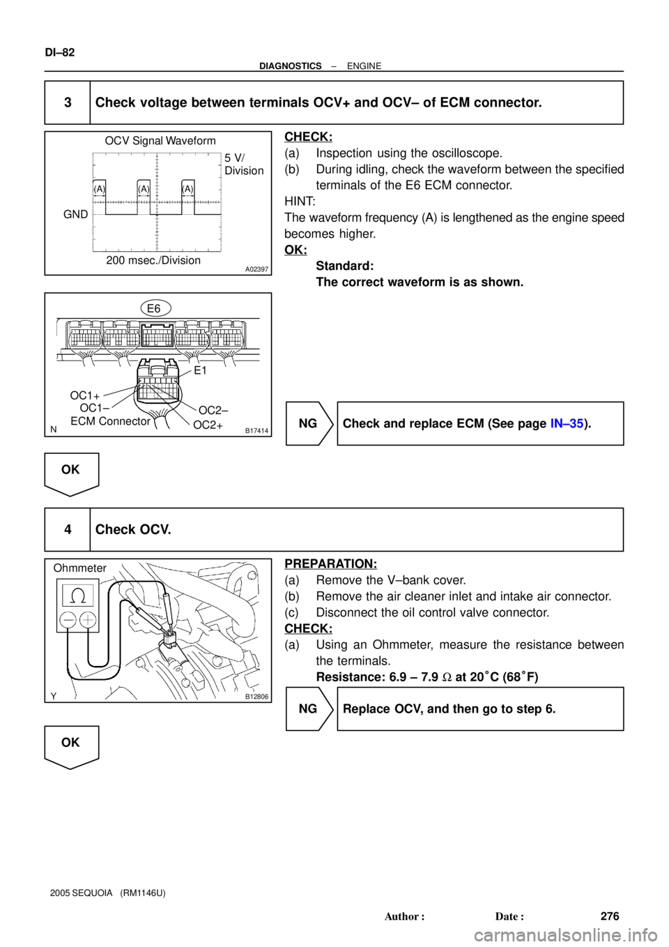
A02397
OCV Signal Waveform
200 msec./Division5 V/
Division
GND
(A) (A) (A)
B17414ECM ConnectorE6
OC1+
OC1±
OC2+OC2±
E1
B12806
Ohmmeter
DI±82
± DIAGNOSTICSENGINE
276 Author�: Date�:
2005 SEQUOIA (RM1146U)
3 Check voltage between terminals OCV+ and OCV± of ECM connector.
CHECK:
(a) Inspection using the oscilloscope.
(b) During idling, check the waveform between the specified
terminals of the E6 ECM connector.
HINT:
The waveform frequency (A) is lengthened as the engine speed
becomes higher.
OK:
Standard:
The correct waveform is as shown.
NG Check and replace ECM (See page IN±35).
OK
4 Check OCV.
PREPARATION:
(a) Remove the V±bank cover.
(b) Remove the air cleaner inlet and intake air connector.
(c) Disconnect the oil control valve connector.
CHECK:
(a) Using an Ohmmeter, measure the resistance between
the terminals.
Resistance: 6.9 ± 7.9 W at 20°C (68°F)
NG Replace OCV, and then go to step 6.
OK
Page 277 of 4323
A02852
A23658
± DIAGNOSTICSENGINE
DI±83
277 Author�: Date�:
2005 SEQUOIA (RM1146U)
5 Check VVT controller assembly.
PREPARATION:
(a) Remove the timing belt (See page EM±16).
(b) Remove the cylinder head cover.
(c) Remove the OCV (See page SF±46).
(d) Drain the oil in the VVT controller assembly
(See page EM±36).
CHECK:
Check whether the oil in VVT controller assembly is drained or
not.
OK:
Standard:
The oil in VVT controller assembly is drained.
NG Replace VVT controller assembly, and then go
to step 6.
OK
6 Check oil control valve filter.
PREPARATION:
(a) Remove the cylinder head cover.
(b) Remove the camshaft bearing cap and OCV filter.
CHECK:
Check that the filter is not clogged.
OK:
The filter is not clogged.
NG Repair or replace.
OK
Page 278 of 4323
DI±84
± DIAGNOSTICSENGINE
278 Author�: Date�:
2005 SEQUOIA (RM1146U)
7 Check whether or not DTC P0010, P0012, P0021 or P0022 is stored.
PREPARATION:
(a) Clear the DTC (See page DI±43).
(b) Perform simulation test.
CHECK:
Check whether or not DTC P0011, P0012, P0021 or P0022 is stored (See page DI±43).
OK:
Standard: DTC P0011, P0012, P0021 or P0022 is not stored.
OK VVT system is OK.*
*: DTC P0011, P0012, P0021 or P0022 is also output when a
foreign object is detected in some parts of the system in the en-
gine oil, and then the system returns to normal in a short time.
As ECM is controlled to eject a foreign object, there is no prob-
lem on the VVT. There is also no problem on the VVT as the oil
filter should catch the foreign object in the engine oil.
NG
Replace ECM.