Page 3362 of 4323
RS11F±01
H23897
± SUPPLEMENTAL RESTRAINT SYSTEMCURTAIN SHIELD AIRBAG ASSEMBLY
RS±71
3354 Author�: Date�:
2005 SEQUOIA (RM1146U)
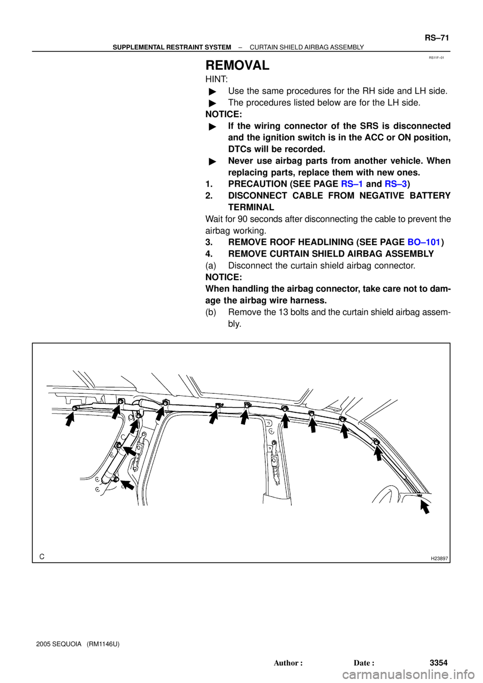
REMOVAL
HINT:
�Use the same procedures for the RH side and LH side.
�The procedures listed below are for the LH side.
NOTICE:
�If the wiring connector of the SRS is disconnected
and the ignition switch is in the ACC or ON position,
DTCs will be recorded.
�Never use airbag parts from another vehicle. When
replacing parts, replace them with new ones.
1. PRECAUTION (SEE PAGE RS±1 and RS±3)
2. DISCONNECT CABLE FROM NEGATIVE BATTERY
TERMINAL
Wait for 90 seconds after disconnecting the cable to prevent the
airbag working.
3. REMOVE ROOF HEADLINING (SEE PAGE BO±101)
4. REMOVE CURTAIN SHIELD AIRBAG ASSEMBLY
(a) Disconnect the curtain shield airbag connector.
NOTICE:
When handling the airbag connector, take care not to dam-
age the airbag wire harness.
(b) Remove the 13 bolts and the curtain shield airbag assem-
bly.
Page 3363 of 4323

INSPECTION
1. VEHICLE NOT INVOLVED IN COLLISION
(a) Perform")
H23919
RS0N4±12
H23898
RS±72
± SUPPLEMENTAL RESTRAINT SYSTEMCURTAIN SHIELD AIRBAG ASSEMBLY
3355 Author�: Date�:
2005 SEQUOIA (RM1146U)
INSPECTION
1. VEHICLE NOT INVOLVED IN COLLISION
(a) Perform a diagnostic system check (see page DI±1147).
(b) With the curtain shield airbag assembly installed on the
vehicle, perform a visual check. If there are any defects
as mentioned below, replace the front pillar garnish or roof
headlining assy with a new one:
Cuts, minute cracks or marked discoloration on the front
pillar garnish or roof headlining assy around the curtain
shield airbag assembly.
2. VEHICLE INVOLVED IN A COLLISION AND AIRBAG IS
NOT DEPLOYED
(a) Perform a diagnostic system check (see page DI±1147).
(b) With the curtain shield airbag assembly removed from the
vehicle, perform a visual check. If there are any defects
as mentioned below, replace the curtain shield airbag as-
sembly with a new one:
�Cuts, tears and cracks, or marked discoloration on
the curtain shield airbag assembly.
�Cracks or other damage to connector.
CAUTION:
For removal and installation of the curtain shield airbag as-
sembly, see page RS±71 and RS±80. Be sure to follow the
correct procedure.
Page 3365 of 4323
 or more
SSTBattery RS±74
± SUPPLEMENTAL RESTRAINT SYSTEMCURTAIN SHIELD AIRBAG ASSEMBLY
3357 Author�: Date�:
2005 SEQUOIA (RM1146U)
1. AIRBAG DEPLO")
AB0158
Battery
SST
H23899
SST
R13455
10 m (33 ft) or more
SSTBattery RS±74
± SUPPLEMENTAL RESTRAINT SYSTEMCURTAIN SHIELD AIRBAG ASSEMBLY
3357 Author�: Date�:
2005 SEQUOIA (RM1146U)
1. AIRBAG DEPLOYMENT WHEN SCRAPPING VE-
HICLE
(a) Check the function of the SST (see step 1±(a) on page
RS±23).
SST 09082±00700
(b) Precaution (see page RS±1 and RS±3).
(c) Disconnect the cable from the negative battery terminal.
Wait for 90 seconds after disconnecting the cable to prevent the
airbag working.
(d) Remove the roof headlining (see page BO±101).
(e) Disconnect the curtain shield airbag connector.
NOTICE:
When handling the airbag connector, be careful not to dam-
age the airbag wire harness.
(f) Install the SST.
(1) Connect the connectors of the SST to the curtain
shield airbag assembly.
SST 09082±00700, 09082±00802 (09082±10801,
09082±20801)
NOTICE:
To avoid damaging the SST connector and wire harness,
do not lock the secondary lock of the twin lock.
(2) Move the SST at least 10 m (33 ft) away from the ve-
hicle rear side window.
(3) Maintaining enough clearance for the SST wire har-
ness in the rear side window, close all doors and
windows of the vehicle.
NOTICE:
Take care not to damage the SST wire harness.
(4) Connect the red clip of the SST to the battery posi-
tive (+) terminal and the black clip of the SST to the
negative (±) terminal.
Page 3370 of 4323

REPLACEMENT
REPLACEMENT REQUIREMENTS
In the following cases, replace the c")
RS0N6±10
± SUPPLEMENTAL RESTRAINT SYSTEMCURTAIN SHIELD AIRBAG ASSEMBLY
RS±79
3362 Author�: Date�:
2005 SEQUOIA (RM1146U)
REPLACEMENT
REPLACEMENT REQUIREMENTS
In the following cases, replace the curtain shield airbag assembly or curtain shield airbag cover with a new
one.
CaseReplacing part
The curtain shield airbag has been deployed.Curtain shield airbag assembly
The curtain shield airbag assembly has been found to be faulty in trouble-
shooting.Curtain shield airbag assembly
The curtain shield airbag assembly has been found to be faulty while check-
ing items
(See page RS±72).
Curtain shield airbag assembly
The front pillar garnish has been found to be faulty while checking items
(See page RS±72).Front pillar garnish
The roof headlining has been found to be faulty while checking items
(See page RS±72).Roof headlining
The curtain shield airbag assembly has been dropped.Curtain shield airbag assembly
CAUTION:
For removal and installation of the curtain shield airbag assembly, see page RS±71 and RS±80. Be
sure to follow the correct procedure.
Page 3371 of 4323

INSTALLATION
HINT:
�Use the same procedures for the RH side and LH")
RS0TH±07
H23897
RS±80
± SUPPLEMENTAL RESTRAINT SYSTEMCURTAIN SHIELD AIRBAG ASSEMBLY
3363 Author�: Date�:
2005 SEQUOIA (RM1146U)
INSTALLATION
HINT:
�Use the same procedures for the RH side and LH side.
�The procedures listed below are for the LH side.
1. INSTALL CURTAIN SHIELD AIRBAG ASSEMBLY
(a) Install the curtain shield airbag assembly with the 13
bolts.
Torque: 9.8 N´m (100 kgf´cm, 7 ft´lbf)
CAUTION:
Pay attention not to twist the deployment section of the cur-
tain shield airbag assembly.
NOTICE:
�If the curtain shield airbag assembly has been
dropped, or there are cracks, dents or other defects
in the case or connector, replace the curtain shield
airbag assembly with a new one.
�When installing the curtain shield airbag assembly,
take care it is not pinched between other parts.
�Never use airbag parts from another vehicle. When
replacing parts, replace them with new ones.
(b) Connect the connector of the curtain shield airbag as-
sembly.
2. INSTALL ROOF HEADLINING (SEE PAGE BO±108)
3. CONNECT CABLE TO NEGATIVE BATTERY TERMI-
NAL
4. PERFORM INITIALIZATION (SEE PAGE BE±77)
Some system need initialization when disconnecting the cable
from the negative battery terminal.
5. INSPECT SRS WARNING LIGHT (SEE PAGE DI±1137)
Page 3428 of 4323
I18638
A. Taillight Relay Instrument Panel J/B:
Relays:
B. Back±Up Light Relay
C. ACC Relay
D. Power Main Relay
E. Fog Light Relay
F. MIRROR HEATER Relay
G. FLASHER Relay
H. SEAT HEATER Relay
Fuses:
1. TAIL Fuse
2. PWR No. 4 Fuse
3. PANEL Fuse
4. ECU±IG Fuse
123
4567
89
1011
12
1314
A
BC
DE
GH
F
15
1617 18 19
20
21 22 23
2425
265. CIG Fuse
6. PWR No. 1 Fuse
7. HTR Fuse
8. WSH Fuse
9. RAD No. 2 Fuse
10. WIP Fuse
11. FOG Fuse
12. AC INV Fuse 15 A
13. 4WD Fuse14. IGN1 Fuse
15. GAUGE Fuse
16. IGN 2 Fuse
17. STOP Fuse
18. SUN ROOF Fuse
19. PWR OUTLET Fuse
20. PWR No. 3 Fuse
21. OBD Fuse
22. PWR No. 2 Fuse
23. SEAT HTR Fuse
24. PWR SEAT Fuse
25. AM1 Fuse
26. PWR No. 5 Fuse 15 A 10 A
20 A
7.5 A
10 A
15 A
25 A
10 A
25 A
7.5 A
25 A
15 A
20 A15 A
20 A
15 A
25 A
15 A
20 A
7.5 A
25 A
15 A
30 A
40 A
30 A BE±16
± BODY ELECTRICALPOWER SOURCE
3420 Author�: Date�:
2005 SEQUOIA (RM1146U)
Page 3452 of 4323

BE2MS±01
I18639
39
13
Front Personal Light Switch
I18755
1 3
Front Personal
Light Switch
I18563
31
Rear Interior Light Switch
I18564
2
3
I28729
31
BE±40
± BODY ELECTRICALINTERIOR LIGHT SYSTEM
3444 Author�: Date�:
2005 SEQUOIA (RM1146U)
INSPECTION
1. w/o Sliding Roof:
INSPECT FRONT PERSONAL LIGHT SWITCH CONTI-
NUITY
(a) Disconnect the connector from the personal light.
(b) Push the personal light switch ON, check that continuity
exists between terminal 9 and terminal 13.
If continuity is not as specified, replace the light assembly or
bulb.
2. w/ Sliding Roof:
INSPECT FRONT PERSONAL LIGHT SWITCH CONTI-
NUITY
(a) Disconnect the connector from the personal light.
(b) Push the personal light switch ON, check that continuity
exists between terminal 1 and terminal 3.
If continuity is not as specified, replace the light assembly or
bulb.
3. w/o RSE or RSA:
INSPECT REAR INTERIOR LIGHT SWITCH CONTINU-
ITY
(a) Disconnect the connector from the doom light.
(b) Push the rear interior light switch ON, check that continu-
ity exists between terminal 1 and terminal 3.
If continuity is not as specified, replace the light assembly or
bulb.
(c) Turn the light switch to DOOR, check that continuity exists
between terminals 2 and 3.
If continuity is not as specified, replace the light assembly or
bulb.
4. w/ RSE or RSA:
INSPECT REAR INTERIOR LIGHT SWITCH CONTINU-
ITY
(a) Disconnect the connector from the rear interior light.
(b) Push the rear interior light switch ON, check that continu-
ity exists between terminal 1 and terminal 3.
If continuity is not as specified, replace the light assembly or
bulb.
Page 3547 of 4323
I21538
Wire Harness Side:
I21537
Wire Harness Side:
± BODY ELECTRICALGARAGE DOOR OPENER SYSTEM
BE±135
3539 Author�: Date�:
2005 SEQUOIA (RM1146U)
3. w/ Sliding Roof:
INSPECT GARAGE DOOR OPENER SWITCH CIRCUIT
Disconnect the connector from the switch and inspect the con-
nector on the wire harness side, as shown.
Tester connectionConditionSpecified condition
1 ± GroundAlwaysContinuity
3 ± GroundAlwaysBattery positive voltage
If the circuit is not as specified, inspect the power source or wire
harness.
4. w/o Sliding Roof:
INSPECT GARAGE DOOR OPENER SWITCH CIRCUIT
Disconnect the connector from the switch and inspect the con-
nector on the wire harness side, as shown.
Tester connectionConditionSpecified condition
9 ± GroundAlwaysBattery positive voltage
13 ± GroundAlwaysContinuity
If the circuit is not as specified, inspect the power source or wire
harness.