Page 1882 of 4323
I28588
BEANBODY ECU
Hi Beam Indicator
Driver Door ECU
A/C ECU
Sliding Roof
Control ECUMPX1
MPX2
MPX3HIND
HRLY
H±ON
DIM
HEAD
TAIL
A
HF
HI
FOGCombination Meter
From
Battery
HEAD
MAIN
Headlight
DRL (*1)
Headlight
DRL No. 4H±LP(*2) DRLH±LP(*2)
Headlight
Headlight H±LP(*1)
H±LP(*1)
H±LP(*1)
H±LP(*1) DIMMER
(*2)
(*2) Combination Switch
Light Control
Switch
Dimmer
Switch
Fog Light
SwitchDRL
Resister
*1: w/ DRL
*2: w/o DRL DI±1680
± DIAGNOSTICSBODY CONTROL SYSTEM
1874 Author�: Date�:
2005 SEQUOIA (RM1146U)
Page 1895 of 4323
± DIAGNOSTICSBODY CONTROL SYSTEM
DI±1693
1887 Author�: Date�:
2005 SEQUOIA (RM1146U) DOP (*2) ± GND1
(B5±9 ± B6±6)
P ± W±BGlass breakage sensor
ECU communicationArmed stateBelow 1 V
DOP (*2) ± GND1
(B5±9 ± B6±6)P ± W±BGlass breakage sensor
ECU communicationAlarm sounds (on glass break-
age detection)Pulse generation
(See page DI±1774)
(*1): w/ Daytime Running Light
(*2): w/ Glass Breakage Sensor
(*3): w/ Automatic Light Control
(*4): w/ Driving Position Memory
(*5): w/ Sliding Roof
Page 1962 of 4323
I28523
Back Door ECU
Sub J/B No. 3 ILE
B118
BF18
BD29
WWWW
J30J/C
J29 FMInstrument Panel J/BBody ECU
1G6
1G5
1M10
1E3
1G13
1G14
1E81M6
1J5ILE B73
1F 10
1M7W
3C
3A3A
3D6 6
16 6I17
Ignition Key
Cylinder Light
12W
R
R6R
J48R
J/C
J49
BC1 LF R
D13 Door Courtesy
Light Rear RH
12
D17 Door Courtesy
Light Switch Rear RH2 1
W±B
BA161
2
2
IN1R
A AJ21
J/C R
R 1B±O
2 1 D8 Diode
(Interior Light No. 1)BC17
R±YR±YW±B RW±B W±BRRRW (*1)
W (*2)
W
R
12 S8 Step Light
V7 Vanity Light RH
V6 Vanity Light LH
R11 Rear Interior Light
(*4) (*3) To Dome Fuse
W±B
W±B
W
G±R(*2)
(*2)
(*2) 1
2
4
de f g bc aR
(*2)
3ON
DoorOFF R
R DI±1760
± DIAGNOSTICSBODY CONTROL SYSTEM
1954 Author�: Date�:
2005 SEQUOIA (RM1146U)
WIRING DIAGRAM
(*1): w/o Sliding Roof, RSE and RSA
(*2): w/ Sliding Roof, RSE or RSA
(*3): w/ Sliding Roof w/ RSE or RSA
(*4): w/ Sliding Roof w/o RSE and RSA
Page 1963 of 4323
I28526
de fg
bc a
D12 Door Courtesy
Light Rear LH
D9 Diode
(Interior Light No. 2)
2 11 2
W±B
R
BA1 7R±Y
R±Y
D16 Door Courtesy
Light Switch Rear LH
1W±B (*1) (*2)O4 O53 9Overhead Module
Personal Light
Rear Interior Light(*2)
(*1)
(*1)
(*1) (*1)ON
DoorOFF
O4 (*1) (*2)O4 O51 13 13
G±R
(*2) O5
10
A
J8
J/C
IEW
(*1) W±B
R
± DIAGNOSTICSBODY CONTROL SYSTEM
DI±1761
1955 Author�: Date�:
2005 SEQUOIA (RM1146U)
(*1): w/o Sliding Roof, RSE and RSA
(*2): w/ Sliding Roof, RSE or RSA
Page 2090 of 4323
DIDF7±01
I28466
DLC 3Front
Passenger
Door ECUBody ECU
A/C ECU Combination
MeterBack Door
ECUDriver Door
ECU
MPX1
MPX2
MPX3
Slide Roof
ECU Memory
Seat ECU
& SwitchMPX1 MPX2 MPX1 MPX2 MPX1 MPX2
MPX± MPX+
MPX1 MPX1
SILAutomatic Light
Control Sensor
Wireless Door
Control Receiver
Airbag Sensor Assy
Diagnostic Bus
BEANCLTS
CLTB
CLTE
PRG
GSW
OBD2PDA DI±1888
± DIAGNOSTICSMULTIPLEX COMMUNICATION SYSTEM
2082 Author�: Date�:
2005 SEQUOIA (RM1146U)
SYSTEM DIAGRAM
Page 2094 of 4323

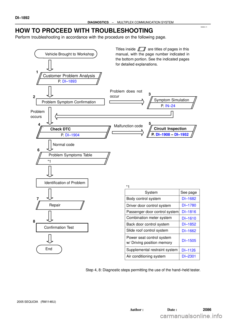
DI3IO±11
Customer Problem Analysis
Vehicle Brought to Workshop
Problem Symptom ConfirmationSymptom Simulation Problem does not
occur
Check DTC
Normal code
Problem Symptoms Table
Identification of Problem
Repair
Confirmation Test
EndTitles inside
are titles of pages in this
manual, with the page number indicated in
the bottom portion. See the indicated pages
for detailed explanations.
1
23
4
6
8P. IN±24
*1P. DI±1893
P. DI±1904Malfunction code
Problem
occurs
Circuit Inspection
P. DI±1908 ± DI±1952
See page
Body control system
Driver door control system
Passenger door control systemSystem
DI±1682
DI±1780
DI±1816
DI±1610
Step 4, 8: Diagnostic steps permitting the use of the hand±held tester.*15
7
Combination meter system
Slide roof control system
DI±1662 DI±1852 Back door control system
Power seat control system
w/ Driving position memoryDI±1505
Supplemental restraint system
Air conditioning systemDI±1126
DI±2301 DI±1892
± DIAGNOSTICSMULTIPLEX COMMUNICATION SYSTEM
2086 Author�: Date�:
2005 SEQUOIA (RM1146U)
HOW TO PROCEED WITH TROUBLESHOOTING
Perform troubleshooting in accordance with the procedure on the following page.
Page 2095 of 4323
DI3IP±10
MULTIPLEX COMMUNICATION SYSTEM Check Sheet
Inspector 's name:
Customer 's Name
Date VehicleVIN
Production Date
Licence Plate No.
Odometer Reading / /km
mile
Weather Conditions
When Problem
Occurred
Date Problem First Occurred
Frequency Problem Occurs
Weather
/ /
Once only Brought in
Malfunction
System
Outdoor Temperature
Fine Cloudy Rainy Snowy
Various/Others
Hot Warm Cool
Cold (Approx. °F ( °C))
Constant Sometimes ( times per day, month)
Driver Door Control System
Passenger Door Control System
Combination Meter System
Body Control System
Back Door Control System
Slide Roof Control System
Power Seat Control System (w/ Driving Position Memory)
Supplemental Restraint System
Air Condition System
± DIAGNOSTICSMULTIPLEX COMMUNICATION SYSTEM
DI±1893
2087 Author�: Date�:
2005 SEQUOIA (RM1146U)
CUSTOMER PROBLEM ANALYSIS CHECK
Page 2100 of 4323
I18632
S19
DI±1898
± DIAGNOSTICSMULTIPLEX COMMUNICATION SYSTEM
2092 Author�: Date�:
2005 SEQUOIA (RM1146U)
4. CHECK SLIDING ROOF ECU
(a) Disconnect the S19 ECU connector.
(b) Measure the resistance or voltage of each terminal of the wire harness side connector.
Standard:
Symbols (Terminals No.)Wiring ColorTerminal DescriptionConditionSpecified Condition
IG (S19±8) ± Body groundB±R ±
Body groundIgnition power supplyIgnition switch ON10 to 14 V
B (S19±5) ± Body groundL±W ±
Body ground+B (BATT) power supplyAlways10 to 14 V
MPX1 (S19±2) ± Body groundG±O ±
Body groundMPX lineAlways10 kW or higher
E (S19±7) ± Body groundW±B ±
Body groundGroundAlwaysBelow 1 W
If the result is not as specified, there may be a malfunction on the wire harness side.