Page 850 of 4323
ECM command gearshift
Shift solenoid valve S21st 2nd 3rd 4th 5th
OFF OFFON OFFON
1
152 3 4 5 6 7 8
9 10 11 12
13 14
D11994
Transmission Wire Side:
(Connector Front View):
E1
S2
DI±648
± DIAGNOSTICSAUTOMATIC TRANSMISSION
842 Author�: Date�:
2005 SEQUOIA (RM1146U)
INSPECTION PROCEDURE
HINT:
�The shift solenoid valve S2 is turned on/off normally when the shift lever is in the D position:
1 Check transmission wire.
PREPARATION:
Disconnect the transmission wire connector.
CHECK:
Measure the resistance according to the value(s) in the table
below.
OK:
Tester ConnectionSpecified Condition
20�C (68�F)
15 ± Body ground11 to 15 W
NG Go to step 3.
OK
Page 855 of 4323
ECM command gearshift
Shift solenoid valve SR1st 2nd 3rd 4th 5th
OFF OFF ONOFF OFF
1
152 3 4 5 6 7 8
9 10 11 12
13 14
D11994
Transmission Wire Side:
(Connector Front View):
E1
SR
± DIAGNOSTICSAUTOMATIC TRANSMISSION
DI±653
847 Author�: Date�:
2005 SEQUOIA (RM1146U)
INSPECTION PROCEDURE
HINT:
�The shift solenoid valve SR is turned on/off normally when the shift lever is in the D position:
1 Check transmission wire.
PREPARATION:
Disconnect the transmission wire connector.
CHECK:
Measure the resistance according to the value(s) in the table
below.
OK:
Tester ConnectionSpecified Condition
20�C (68�F)
7 ± Body ground11 to 15 W
NG Go to step 3.
OK
Page 865 of 4323
D14174
ECM
SLT+
SLT± E713
12 B±R
G±Y E1 Electronically Controlled
Transmission Solenoid
E7 G
GR14
6 SLT+
SLT±+B
1
152 3 4 5 6 7 8
9 10 11 12
13 14
D11994
Transmission Wire Side:
(Connector Front View):
E1
SLT±
SLT+
± DIAGNOSTICSAUTOMATIC TRANSMISSION
DI±663
857 Author�: Date�:
2005 SEQUOIA (RM1146U)
WIRING DIAGRAM
INSPECTION PROCEDURE
1 Check transmission wire.
PREPARATION:
Disconnect the transmission wire connector.
CHECK:
Measure the resistance according to the value(s) in the table
below.
OK:
Tester ConnectionSpecified Condition
20�C (68�F)
14 (SLT+) ± 6 (SLT±)5.0 to 5.6 W
CHECK:
Measure the resistance according to the value(s) in the table
below.
OK:
Tester ConnectionSpecified Condition
14 (SLT+) ± Body ground10 kW or higher
6 (SLT±) ± Body ground=
NG Go to step 3.
OK
Page 884 of 4323
1
152 3 4 5 6 7 8
9 10 11 12
13 14
D11994
Transmission Wire Side:
(Connector Front View):
E1
SLU±
SLU+
DI±682
± DIAGNOSTICSAUTOMATIC TRANSMISSION
876 Author�: Date�:
2005 SEQUOIA (RM1146U)
INSPECTION PROCEDURE
1 Inspect transmission wire.
PREPARATION:
Disconnect the transmission wire connector.
CHECK:
Measure the resistance according to the value(s) in the table
below.
OK:
Tester ConnectionSpecified Condition
20�C (68�F)
13 (SLU+) ± 5 (SLU±)5.0 to 5.6 W
CHECK:
Measure the resistance according to the value(s) in the table
below.
OK:
Tester ConnectionSpecified Condition
13 (SLU+) ± Body ground10 kW or higher
5 (SLU±) ± Body ground=
NG Go to step 3.
OK
Page 935 of 4323

F19456
Wire Harness Connector
Front View:
H15
SHB
SHG
F16805
S25
Suspension Control ECU
Wire Harness View:
SGL
SBL
F19456
Height Control Sensor Sub±assy
Connector Front View:
SHG H15
SHB
± DIAGNOSTICSAIR SUSPENSION SYSTEM
DI±733
927 Author�: Date�:
2005 SEQUOIA (RM1146U)
2 Check harness and connector (Height control sensor sub±assy power source).
PREPARATION:
(a) Disconnect the height control sensor sub±assy connec-
tor.
(b) Turn the ignition switch ON.
CHECK:
Measure the voltage between terminals 1 (SHB) and 3 (SHG)
of the height control sensor sub±assy wire harness side con-
nector.
OK:
Voltage: 4.5 to 5.5 V
OK Go to step 4.
NG
3 Check harness and connector (Height control sensor sub±assy ± Suspension
control ECU).
PREPARATION:
Disconnect the ECU connector.
CHECK:
(a) Check for an open or short circuit in the harness and the
connector between terminal 1 (SHB) of the height control
sensor sub±assy and S25±15 (SBL) of the suspension
control ECU.
(b) Check for an open or short circuit in the harness and the
connector between terminal 3 (SHG) of the height control
sensor sub±assy and S25±19 (SGL) of the suspension
control ECU.
OK:
There is no open or short circuit in the wire harness.
Page 1097 of 4323
DI939±04
Vehicle Brought to Workshop
Customer Problem Analysis
P. DI±896
Check and Clear DTC
P. DI±911Items inside
are titles of pages in this manual,
with the page number in the bottom portion. See
the pages for detailed explanations.
Problem Symptom ConfirmationSymptom Simulation
P. IN±24
Symptom
does not occur
Symptom
occurs
DTC Check
P. DI±911
Sensor CheckCircuit Inspection
DTC Chart
P. DI±921Trouble codeProblem Symptoms Table
P. DI±905
Check for Fluid Leakage
P. DI±1059
Identification of Problem
Normal system code
Repair
Confirmation Test
End
1
2
3
4
5
67
89
10
11Step 2, 5, 8, 9, 11:
P. DI±925 ± DI±1057
Diagnostic steps permitting use of the
hand±held tester.
± DIAGNOSTICSABS WITH EBD & BA & TRAC & VSC SYSTEM
DI±895
1089 Author�: Date�:
2005 SEQUOIA (RM1146U)
HOW TO PROCEED WITH TROUBLESHOOTING
Troubleshoot in accordance with the following procedures:
Page 1190 of 4323
F19146
Master Cylinder
Pressure Sensor
No. 1Master Cylinder
Pressure Sensor
No. 2
VCM E1VCM2
E2
M3 M2
DI±988
± DIAGNOSTICSABS WITH EBD & BA & TRAC & VSC SYSTEM
1182 Author�: Date�:
2005 SEQUOIA (RM1146U)
INSPECTION PROCEDURE
1 Check battery positive voltage.
OK:
Voltage: 10 to 14 V
NG Check and repair the charging system
(See page CH±1).
OK
2 Check master cylinder pressure sensor No. 1 and No. 2.
PREPARATION:
Disconnect the master cylinder pressure sensor connectors
No. 1 and No. 2.
CHECK:
(1) Turn the ignition switch to the ON position.
(2) Measure the voltage between terminal VCM and
E1, VCM2 and E2 of the harness side connector.
OK:
Voltage: 4.5 to 5.5 V
NG Go to step 4.
OK
Page 1191 of 4323
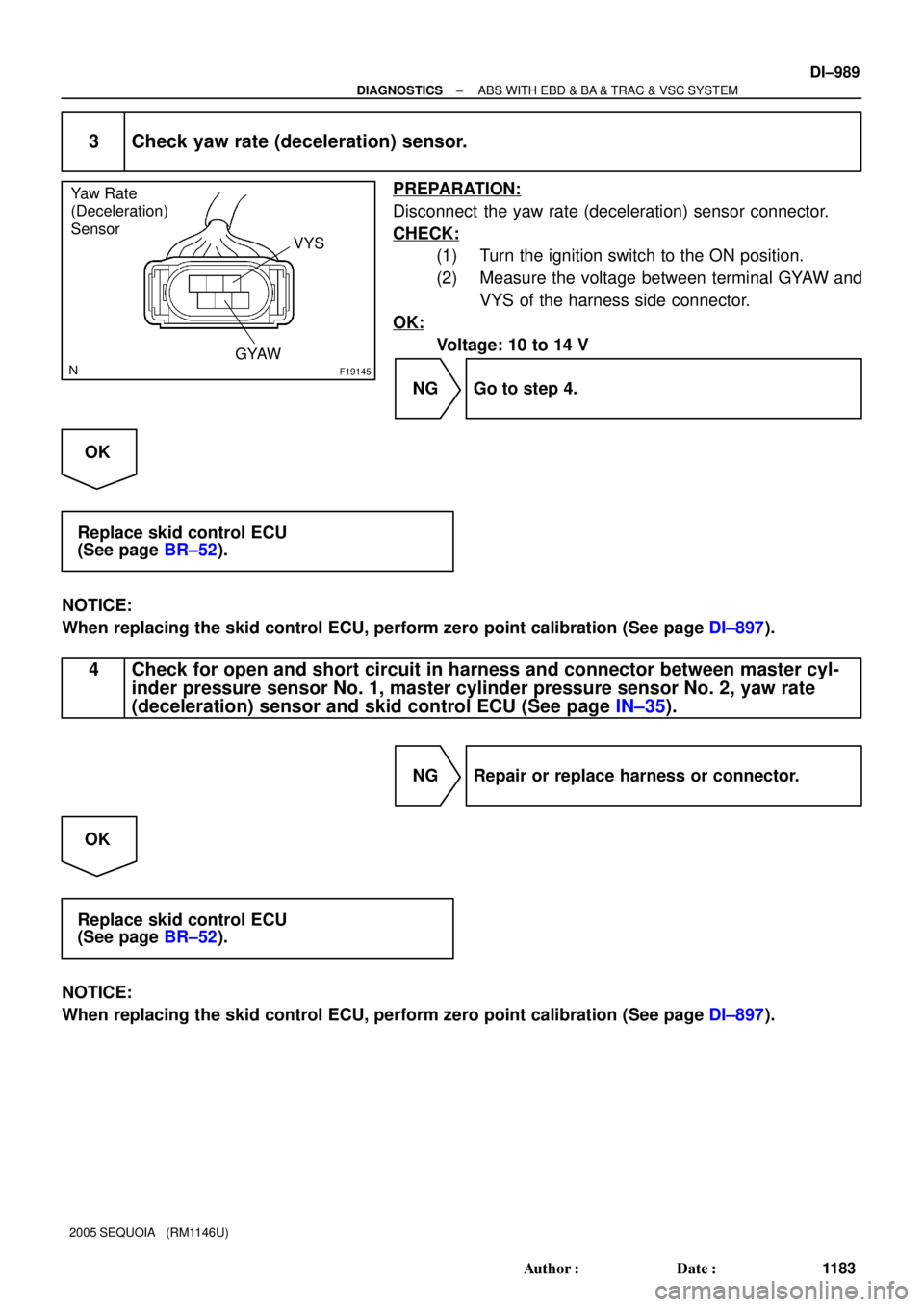
F19145
Yaw Rate
(Deceleration)
Sensor
VYS
GYAW
± DIAGNOSTICSABS WITH EBD & BA & TRAC & VSC SYSTEM
DI±989
1183 Author�: Date�:
2005 SEQUOIA (RM1146U)
3 Check yaw rate (deceleration) sensor.
PREPARATION:
Disconnect the yaw rate (deceleration) sensor connector.
CHECK:
(1) Turn the ignition switch to the ON position.
(2) Measure the voltage between terminal GYAW and
VYS of the harness side connector.
OK:
Voltage: 10 to 14 V
NG Go to step 4.
OK
Replace skid control ECU
(See page BR±52).
NOTICE:
When replacing the skid control ECU, perform zero point calibration (See page DI±897).
4 Check for open and short circuit in harness and connector between master cyl-
inder pressure sensor No. 1, master cylinder pressure sensor No. 2, yaw rate
(deceleration) sensor and skid control ECU (See page IN±35).
NG Repair or replace harness or connector.
OK
Replace skid control ECU
(See page BR±52).
NOTICE:
When replacing the skid control ECU, perform zero point calibration (See page DI±897).
:
E1
S2
DI±648
± DIAGNOSTICSA")
:
E1
SR
± DIAGNOSTICSAUTOMAT")