Page 685 of 4323
A23446
L5
A23508
Wire Harness Side:
Canister Connector
Front View
L5
± DIAGNOSTICSENGINE
DI±483
677 Author�: Date�:
2005 SEQUOIA (RM1146U)
21 Inspect pump module power source circuit.
PREPARATION:
(a) Turn the ignition switch to OFF.
(b) Disconnect the L5 canister connector.
(c) Turn the ignition switch to ON.
CHECK:
Measure the voltage between terminal 9 of the canister connec-
tor and the body ground.
RESULT:
Test ResultsSuspected Trouble AreasProceed To
Between 9 V and 14 VNormalA
Between 0 V and 3 VPower source wire harness of vent valveB
B Go to step 32.
A
Page 687 of 4323
A23446
L5
A23508
Wire Harness Side:
Canister Connector
Front View
L5
± DIAGNOSTICSENGINE
DI±485
679 Author�: Date�:
2005 SEQUOIA (RM1146U)
24 Check for open and short circuit in harness and connecter between pump mod-
ule and ECM.
PREPARATION:
(a) Turn the ignition switch to OFF.
(b) Disconnect the L5 canister connector.
(c) Turn the ignition switch to ON.
(d) On the hand±held tester, select the following menu
items:DIAGNOSIS / ENHANCED OBD II / ACTIVE TEST
/ VACUUM PUMP (ALONE).
(e) Turn the vacuum pump ON.
CHECK:
Measure the voltage between terminal 1 of the canister connec-
tor and the body ground.
RESULT:
Test ResultsSuspected Trouble AreasProceed To
Between 9 V and 14 VNormalA
Between 0 V and 3 VWire harness between ECM and vacuum pumpB
B Go to step 32.
A
Page 688 of 4323
A23508
Wire Harness Side:
Canister Connector
Front View
L5
DI±486
± DIAGNOSTICSENGINE
680 Author�: Date�:
2005 SEQUOIA (RM1146U)
25 Check for open and short in harness and connector between pump module and
ECM.
PREPARATION:
(a) Disconnect the L5 canister connector.
(b) Turn the ignition switch to OFF.
CHECK:
Check the resistance between terminal 6 of the canister con-
nector and the body ground.
RESULT:
Test ResultsSuspected Trouble AreasProceed To
Below 1 WVacuum pumpA
10 kW or moreWire harness between vacuum pump and body
groundB
A Go to step 30.
B Go to step 32.
26 Inspect throttle body.
PREPARATION:
(a) Stop the engine.
(b) Disconnect the EVAP hose from the throttle body.
(c) Start the engine.
CHECK:
(a) Use your finger to confirm that the port of the throttle body has suction.
RESULT:
Test ResultsSuspected Trouble AreasProceed To
Suction appliedEVAP hose between throttle body and purge VSVA
No suctionThrottle bodyB
A Go to step 33.
B Go to step 34.
Page 689 of 4323

A23477SST
Pressure Gauge
Pressure
B06546
± DIAGNOSTICSENGINE
DI±487
681 Author�: Date�:
2005 SEQUOIA (RM1146U)
27 Correctly reinstall or replace fuel tank cap.
HINT:
�When reinstalling the fuel tank cap, tighten it until a few click sounds are heard.
�When replacing the fuel tank cap, use a fuel tank cap that meets OEM specifications, and install it until
a few click sounds are heard.
NEXT Go to step 37.
28 Replace fuel tank cap.
HINT:
When installing the fuel tank cap, tighten it until a few click sounds are heard.
NEXT Go to step 37.
29 Repair EVAP leak part.
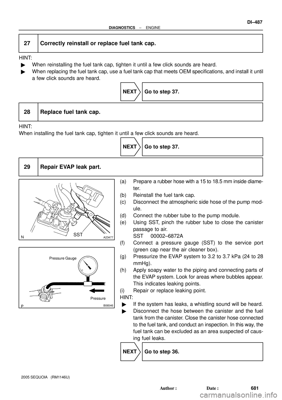
(a) Prepare a rubber hose with a 15 to 18.5 mm inside diame-
ter.
(b) Reinstall the fuel tank cap.
(c) Disconnect the atmospheric side hose of the pump mod-
ule.
(d) Connect the rubber tube to the pump module.
(e) Using SST, pinch the rubber tube to close the canister
passage to air.
SST 00002±6872A
(f) Connect a pressure gauge (SST) to the service port
(green cap near the air cleaner box).
(g) Pressurize the EVAP system to 3.2 to 3.7 kPa (24 to 28
mmHg).
(h) Apply soapy water to the piping and connecting parts of
the EVAP system. Look for areas where bubbles appear.
This indicates leaking points.
(i) Repair or replace leaking point.
HINT:
�If the system has leaks, a whistling sound will be heard.
�Disconnect the hose between the canister and the fuel
tank from the canister. Close the canister hose connected
to the fuel tank, and conduct an inspection. In this way, the
fuel tank can be excluded as an area suspected of caus-
ing fuel leaks.
NEXT Go to step 36.
Page 727 of 4323

D14137
Refill Plug
Overflow Plug
D14142Control Shaft Lever
± DIAGNOSTICSAUTOMATIC TRANSMISSION
DI±525
719 Author�: Date�:
2005 SEQUOIA (RM1146U)
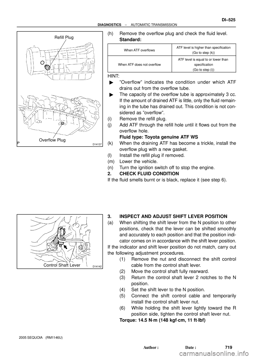
(h) Remove the overflow plug and check the fluid level.
Standard:
When ATF overflowsATF level is higher than specification
(Go to step (k))
When ATF does not overflow
ATF level is equal to or lower than
specification
(Go to step (i))
HINT:
�ºOverflowº indicates the condition under which ATF
drains out from the overflow tube.
�The capacity of the overflow tube is approximately 3 cc.
If the amount of drained ATF is little, only the fluid remain-
ing in the tube has drained out. This condition is not con-
sidered as ºoverflowº.
(i) Remove the refill plug.
(j) Add ATF through the refill hole until it flows out from the
overflow hole.
Fluid type: Toyota genuine ATF WS
(k) When the draining ATF has become a trickle, install the
overflow plug with a new gasket.
(l) Install the refill plug if removed.
(m) Lower the vehicle.
(n) Turn the ignition switch off to stop the engine.
2. CHECK FLUID CONDITION
If the fluid smells burnt or is black, replace it (see step 6).
3. INSPECT AND ADJUST SHIFT LEVER POSITION
(a) When shifting the shift lever from the N position to other
positions, check that the lever can be shifted smoothly
and accurately to each position and that the position indi-
cator comes on in accordance with the shift lever position.
If the indicator and shift lever position do not match, carry out
the following adjustment procedures.
(1) Remove the nut and disconnect the shift control
cable from the control shaft lever.
(2) Move the control shaft fully rearward.
(3) Return the control shaft lever 2 notches to the N
position.
(4) Set the shift lever to the N position.
(5) Connect the shift control cable and temporarily
install the control shaft lever nut.
(6) While holding the shift lever lightly toward the R
position side, tighten the control shaft lever nut.
Torque: 14.5 N´m (148 kgf´cm, 11 ft´lbf)
Page 807 of 4323
ECM command gearshift
Shift solenoid valve SL11st 2nd 3rd 4th 5th
OFF OFF OFF ONOFF
1
152 3 4 5 6 7 8
9 10 11 12
13 14
D11994
SL1±
SL1+
E1
Transmission Wire Side:
(Connector Front View):
± DIAGNOSTICSAUTOMATIC TRANSMISSION
DI±605
799 Author�: Date�:
2005 SEQUOIA (RM1146U)
INSPECTION PROCEDURE
HINT:
�The shift solenoid valve SL1 is turned on/off normally when the shift lever is in the D position:
1 Inspect transmission wire.
PREPARATION:
Disconnect the transmission wire connector.
CHECK:
Measure the resistance according to the value(s) in the table
below.
OK:
Tester ConnectionSpecified Condition
20�C (68�F)
12 (SL1+) ± 4 (SL1±)5.0 to 5.6 W
CHECK:
Measure the resistance according to the value(s) in the table
below.
OK:
Tester ConnectionSpecified Condition
12 (SL1+) ± Body ground10 kW or higher
4 (SL1±) ± Body ground=
NG Go to step 3.
OK
Page 835 of 4323
ECM command gearshift
Shift solenoid valve SL21st 2nd 3rd 4th 5th
ON
OFF ON ON ON
1
152 3 4 5 6 7 8
9 10 11 12
13 14
D11994SL2+
SL2±
Transmission Wire Side:
(Connector Front View):
E1
± DIAGNOSTICSAUTOMATIC TRANSMISSION
DI±633
827 Author�: Date�:
2005 SEQUOIA (RM1146U)
INSPECTION PROCEDURE
HINT:
�The shift solenoid valve SL2 is turned on/off normally when the shift lever is in the D position:
1 Inspect transmission wire.
PREPARATION:
Disconnect the transmission wire connector.
CHECK:
Measure the resistance according to the value(s) in the table
below.
OK:
Tester ConnectionSpecified Condition
20�C (68�F)
11 (SL2+) ± 3 (SL2±)5.0 to 5.6 W
CHECK:
Measure the resistance according to the value(s) in the table
below.
OK:
Tester ConnectionSpecified Condition
11 (SL2+) ± Body ground10 kW or higher
3 (SL2±) ± Body ground=
NG Go to step 3.
OK
Page 845 of 4323
ECM command gearshift
Shift solenoid valve S11st 2nd 3rd 4th 5th
OFF OFF ON OFF ON
1
152 3 4 5 6 7 8
9 10 11 12
13 14
D11994
Transmission Wire Side:
(Connector Front View):
E1
S1
± DIAGNOSTICSAUTOMATIC TRANSMISSION
DI±643
837 Author�: Date�:
2005 SEQUOIA (RM1146U)
INSPECTION PROCEDURE
HINT:
�The shift solenoid valve S1 is turned on/off normally when the shift lever is in the D position:
1 Check transmission wire.
PREPARATION:
Disconnect the transmission wire connector.
CHECK:
Measure the resistance according to the value(s) in the table
below.
OK:
Tester ConnectionSpecified Condition
20�C (68�F)
8 ± Body ground11 to 15 W
NG Go to step 3.
OK