Page 1900 of 4323

� H±LP LH Fuse (*2)
� DRL Fuse (*1)
Rear Washer Motor
Horn
Headlight
Rear washer switch
Igni")
DI94R±07
I28393
Hood Courtesy Switch Engine Room J/B
� ECU±B Fuse
� Door No. 2 Fuse
� H±LP RH Fuse (*2)
� H±LP LH Fuse (*2)
� DRL Fuse (*1)
Rear Washer Motor
Horn
Headlight
Rear washer switch
Ignition Switch
� Key Unlock Switch
DLC3 Body ECU
Instrument Panel J/B
� ECU±IG Fuse
� RAD No. 2 Fuse
� FOG Fuse
� FOG LIGHT Relay
� POWER MAIN Relay
� WSH Fuse
� STOP Fuse
� TAILLIGHT Relay Back Door Power
Window SwitchTheft Horn
Engine Room R/B
No.2
� DIMMER Relay
� DRL No. 4 Relay
� H±LP RH Fuse (*1)
� H±LP LH Fuse (*1)
� H±LP RL Fuse (*1)
� H±LP LL Fuse (*1)
Fog Light
Wireless Door
Control Receiver Wireless Door Lock Buzzer
Combination Meter Memory Seat Switch
(*1): w/ Daytime Running Light
(*2): w/o Daytime Running Light (Located behind
the instrument panel)
(Located behind
the heater control panel)
� DOME Fuse
� HEAD Relay
� HORN Relay
� DOME Fuse
Automatic Light Control Sensor
Stop Light Switch
Remote Control Mirror SwitchGlass Breakage
Sensor Microphone Glass Breakage
Sensor ECU
Combination Switch
� Light Control Switch
� Headlight Dimmer Switch
� Fog Light Switch DI±1698
± DIAGNOSTICSBODY CONTROL SYSTEM
1892 Author�: Date�:
2005 SEQUOIA (RM1146U)
PARTS LOCATION
Page 1901 of 4323
I28394
Parking Brake Switch
Door Lock Motor
Rear Power
Window Motor Courtesy Light
Switch
Courtesy LightRear Courtesy Light Switch Horn Switch
Stop Light Rear Room Light Front Map Light
Courtesy Light Rear Courtesy
Light Switch Door Lock Motor
Rear Power
Window MotorRear Window Control
Switch RH Door Lock Motor
Power Window Switch
� Passenger Door ECU
� Door Lock Control Switch
� Power Window Switch
Stop Light
Power Window
Master Switch
� Driver
Door ECU
� Door Lock
Control Switch
� Power
Window Switch
� Window Lock
Switch
Door Lock Motor
Rear Window
Control Switch LH
± DIAGNOSTICSBODY CONTROL SYSTEM
DI±1699
1893 Author�: Date�:
2005 SEQUOIA (RM1146U)
Page 1902 of 4323
DI94S±08
DI±1700
± DIAGNOSTICSBODY CONTROL SYSTEM
1894 Author�: Date�:
2005 SEQUOIA (RM1146U)
CIRCUIT INSPECTION
Power source circuit
CIRCUIT DESCRIPTION
This circuit provides power to operate the body ECU.
BDR terminal: Power source for door lock motor
S+B terminal: Power source for security horn
ACC terminal: Power source for accessory
BECU terminal: Power source for backing up body ECU
IG terminal: Power source for starting body ECU
WIG terminal: Power source for washer motor
Page 1903 of 4323
I28515
Engine Room J/B
Body ECU
Instrument Panel J/B SECURITY
I18
Ignition SWBDR
ACC
BECU S+B B6 L±W
IA5 2D
2C2H
1C 1E
1G
1L
1G
1G1C 1C 1J12
3
45
6 7
10
11
5
6 2
58 1101332
1
6L±W
IA510
B6
B7
B6 1
2 1
8
12DOOR No. 2
ECU±BShort
Pin
2W±L
W±L
W±R
B B
WGR
W±R
P RAD No. 2
AM1
WSH
ECU±IG12AM1
ACC
B7 IG1 W±L
ALT R/B
F10
FL Block
BatteryL±YB±RB±Y
B
W±BB7
B6
IE 12
IG
WIG
GND1 1W±R 12
3A 3ESub J/B No. 3
4Engine Room R/B No. 2
± DIAGNOSTICSBODY CONTROL SYSTEM
DI±1701
1895 Author�: Date�:
2005 SEQUOIA (RM1146U)
WIRING DIAGRAM
Page 1908 of 4323

I24351
Body ECU
11 3
21 5
B 5W
1G TAILLIGHT Relay
To Taillight
F10
Fusible Link BlockLG
B7
ALTTRLY 2 1L
81
BatteryInstrument Panel J/B
LG
DDJ/9
J/C DI±1706
± DIAGNOSTICSBODY CONTROL SYSTEM
1900 Author�: Date�:
2005 SEQUOIA (RM1146U)
Taillight Relay Circuit
CIRCUIT DESCRIPTION
TAILLIGHT relay will be ºONº by operating the light control switch. The transistor which activates the tail light
relay has two sorts: one is activated by the light control switch for fail safe and the other is activated by CPU.
When the theft deterrent system is activated, it causes the transistor in the ECU to switch ON and OFF at
approximately 0.4 sec. intervals. This switches the TAILLIGHT relay ON and OFF, and thus flashing the tail-
lights (See the wiring diagram below).
In this condition, if any of the following operations is done, the transistor in the ECU goes OFF and the TAIL-
LIGHT relay switches OFF, and thus stopping the taillights flashing:
(1) Unlock the front LH or RH door with a key.
(2) Turn the ignition switch to ACC or ON position.
(3) Unlock the doors with the wireless door lock control system.
(4) Wait for approximately 60 seconds.
WIRING DIAGRAM
DI6QY±15
Page 1910 of 4323
: w/ Daytime Running Light
(*2): w/o Daytime Runn")
I24144
Body ECU
MAINEngine Room J/B
HEAD Relay
Instrument Panel J/B
Battery
LG±R 2D
B12FL
R±W
12 532F
2G
2C
B7 1G 1JL
R±L
R±L
HRLY 8
6
1
6
1
2
(*1): w/ Daytime Running Light
(*2): w/o Daytime Running LightLG±R69 8 To Headlight RH To Headlight LH To DRL No.4 Relay To DIMMER Relay To DIMMER Relay
B 4
5 F10
FL Block(*2) (*2) (*1)
(*1)
(*1)
H±LP RH (*2)
DRL (*1)
H±LP LH (*2)
(*1) DI±1708
± DIAGNOSTICSBODY CONTROL SYSTEM
1902 Author�: Date�:
2005 SEQUOIA (RM1146U)
Headlight Relay Circuit
CIRCUIT DESCRIPTION
HEAD relay will be ºONº by operating the light control switch. The transistor which activates the HEAD relay
has two sorts: one is activated by the light control switch for fail safe and the other is activated by CPU. The
one that is activated by CPU prevents the headlight from turning off at the time of trouble with the other sys-
tem in the automatic operation circuit.
When the theft deterrent system is activated, it causes the transistor in the ECU to switch ON and OFF at
approximately 0.25 sec. intervals. This switches the HEAD relay ON and OFF, and thus flashing the head-
lights (See the wiring diagram below).
In this condition, if any of the following operations is done, the transistor in the ECU goes OFF and the HEAD
control relay switches OFF, and thus stopping the headlights flashing:
(1) Unlock the front LH or RH door with a key.
(2) Turn the ignition switch to ACC or ON position.
(3) Unlock the doors with the wireless door lock control system.
(4) Wait for approximately 60 seconds.
WIRING DIAGRAM
DI5VQ±14
Page 1922 of 4323
I24353
Body ECU
BC1ACT± J11 J10 D18
Door Lock Motor
Rear LH
J10
J10
J10 J11
J11
J11
J11B5
B5
B7ACT+
IB1 BC1 BA1
2
ACTD L±B
10 9
L±B L±B
L±B
L±B
L±R
L±R L±R
L±RL±R L±R
D21
Door Lock
Motor
Front RH
D20
Door Lock
Motor Front
LHD19
Door Lock
Motor Rear RHL±B
L±R
L±R
R±B L±BL±B
L±B
L±R L±R
R±B2 6
5
1 2
4 3 2
1
13C
A
12 10C
D
D
A E EE10
1
II2 IB1 BA1II2
10
9J/C
L±R
J/C
KD
NG J45
J44 DJJ/C
J34J33
CJ/C
I
J34
J33
J45
J44 DI±1720
± DIAGNOSTICSBODY CONTROL SYSTEM
1914 Author�: Date�:
2005 SEQUOIA (RM1146U)
Door lock motor circuit
CIRCUIT DESCRIPTION
The body ECU actuates the door lock motor when it receives a motor drive signal from the wireless transmit-
ter or an ECU via BEAN.
WIRING DIAGRAM
DI573±11
Page 1923 of 4323
± DIAGNOSTICSBODY CONTROL SYSTEM
DI±1721
1915 Author�: Date�:
2005 SEQUOIA (RM1146U)
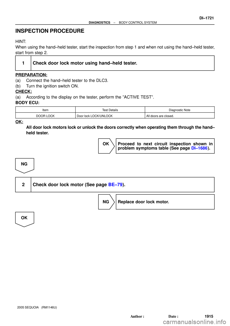
INSPECTION PROCEDURE
HINT:
When using the hand±held tester, start the inspection from step 1 and when not using the hand±held tester,
start from step 2.
1 Check door lock motor using hand±held tester.
PREPARATION:
(a) Connect the hand±held tester to the DLC3.
(b) Turn the ignition switch ON.
CHECK:
(a) According to the display on the tester, perform the ºACTIVE TESTº.
BODY ECU:
ItemTest DetailsDiagnostic Note
DOOR LOCKDoor lock LOCK/UNLOCKAll doors are closed.
OK:
All door lock motors lock or unlock the doors correctly when operating them through the hand±
held tester.
OK Proceed to next circuit inspection shown in
problem symptoms table (See page DI±1686).
NG
2 Check door lock motor (See page BE±79).
NG Replace door lock motor.
OK