Page 1989 of 4323
DI1PA±08
I28392
Power Window Master Switch
� Driver Door ECU
� Power Window Switch
� Door Lock Control Switch
� Window Lock Switch
Door Courtesy LightDoor Lock Assembly
� Door Lock Motor
� Door Unlock Detection
Switch Power Window Motor
� Pulse Sensor
� Limit Switch
Door Courtesy Light Switch � Driver door ECU is the same with power window master switch.
Door Key Lock and
Unlock Switch Remote Control Mirror
(w/ Driving Position Memory)
± DIAGNOSTICSDRIVER DOOR CONTROL SYSTEM
DI±1787
1981 Author�: Date�:
2005 SEQUOIA (RM1146U)
PARTS LOCATION
Page 1990 of 4323
DI1PD±10
I28457
F10
Fusible Link Block
Engine Room J/B
Sub J/B No. 3
SHORT PIN
D22
Driver Door ECU
SIG 21 A
W±LB±R 9
IB1 J/C
W±R ECU±B
Battery
IEB±R A
B±RInstrument Panel J/B
ECU±IG 4
1FI18
Ignition SW
IG1 AM1 4
1C
B±Y21
6
1C AM1
ALT
L±WPWR No. 12 1 1
1L
1
1F 58
W
4
B
13
IB1L±W
BDR
CPUB
GND Instrument Panel J/B
2
1E 3
1J 8
2C 1
2D
W±R 1
3A 1
3C
W±R1
IB1W±R
23 B
A J8
J/C
W±BJ/C
D
J6F
J7W±B
13 25 B±RJ37 J38
Sub J/B No. 3
3A 3C88 DI±1788
± DIAGNOSTICSDRIVER DOOR CONTROL SYSTEM
1982 Author�: Date�:
2005 SEQUOIA (RM1146U)
CIRCUIT INSPECTION
Power source circuit
CIRCUIT DESCRIPTION
This circuit provides power to operate the driver door ECU.
WIRING DIAGRAM
Page 1993 of 4323
I18711
D20
Door Unlock Detection
SW Front LHD22
Driver Door ECU
LSWD
LSWE 24
9 R±Y
W±B
34
± DIAGNOSTICSDRIVER DOOR CONTROL SYSTEM
DI±1791
1985 Author�: Date�:
2005 SEQUOIA (RM1146U)
Door unlock detection switch circuit
CIRCUIT DESCRIPTION
The door unlock detection switch is built in the door lock motor. This switch is ON when the door lock knob
is in the unlock position and OFF when the lock knob is in the lock position. The ECU detects the door lock
knob conditions in this circuit. It is used as one of the operating conditions for the key confinement prevention
function.
WIRING DIAGRAM
DI1PG±16
Page 1994 of 4323
DI±1792
± DIAGNOSTICSDRIVER DOOR CONTROL SYSTEM
1986 Author�: Date�:
2005 SEQUOIA (RM1146U)
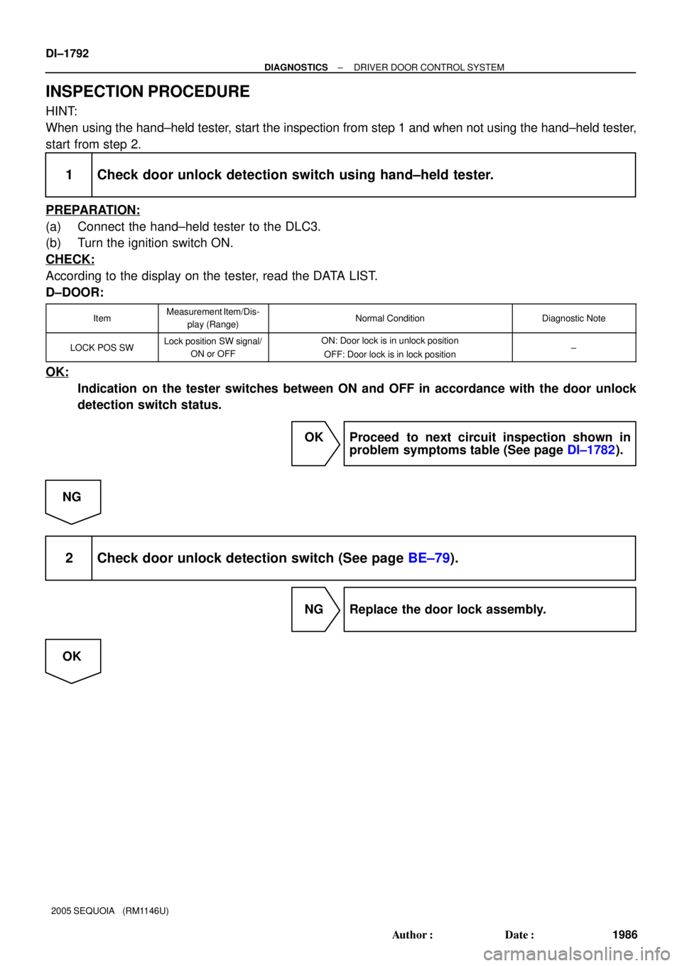
INSPECTION PROCEDURE
HINT:
When using the hand±held tester, start the inspection from step 1 and when not using the hand±held tester,
start from step 2.
1 Check door unlock detection switch using hand±held tester.
PREPARATION:
(a) Connect the hand±held tester to the DLC3.
(b) Turn the ignition switch ON.
CHECK:
According to the display on the tester, read the DATA LIST.
D±DOOR:
ItemMeasurement Item/Dis-
play (Range)Normal ConditionDiagnostic Note
LOCK POS SWLock position SW signal/
ON or OFFON: Door lock is in unlock position
OFF: Door lock is in lock position±
OK:
Indication on the tester switches between ON and OFF in accordance with the door unlock
detection switch status.
OK Proceed to next circuit inspection shown in
problem symptoms table (See page DI±1782).
NG
2 Check door unlock detection switch (See page BE±79).
NG Replace the door lock assembly.
OK
Page 1995 of 4323
± DIAGNOSTICSDRIVER DOOR CONTROL SYSTEM
DI±1793
1987 Author�: Date�:
2005 SEQUOIA (RM1146U)
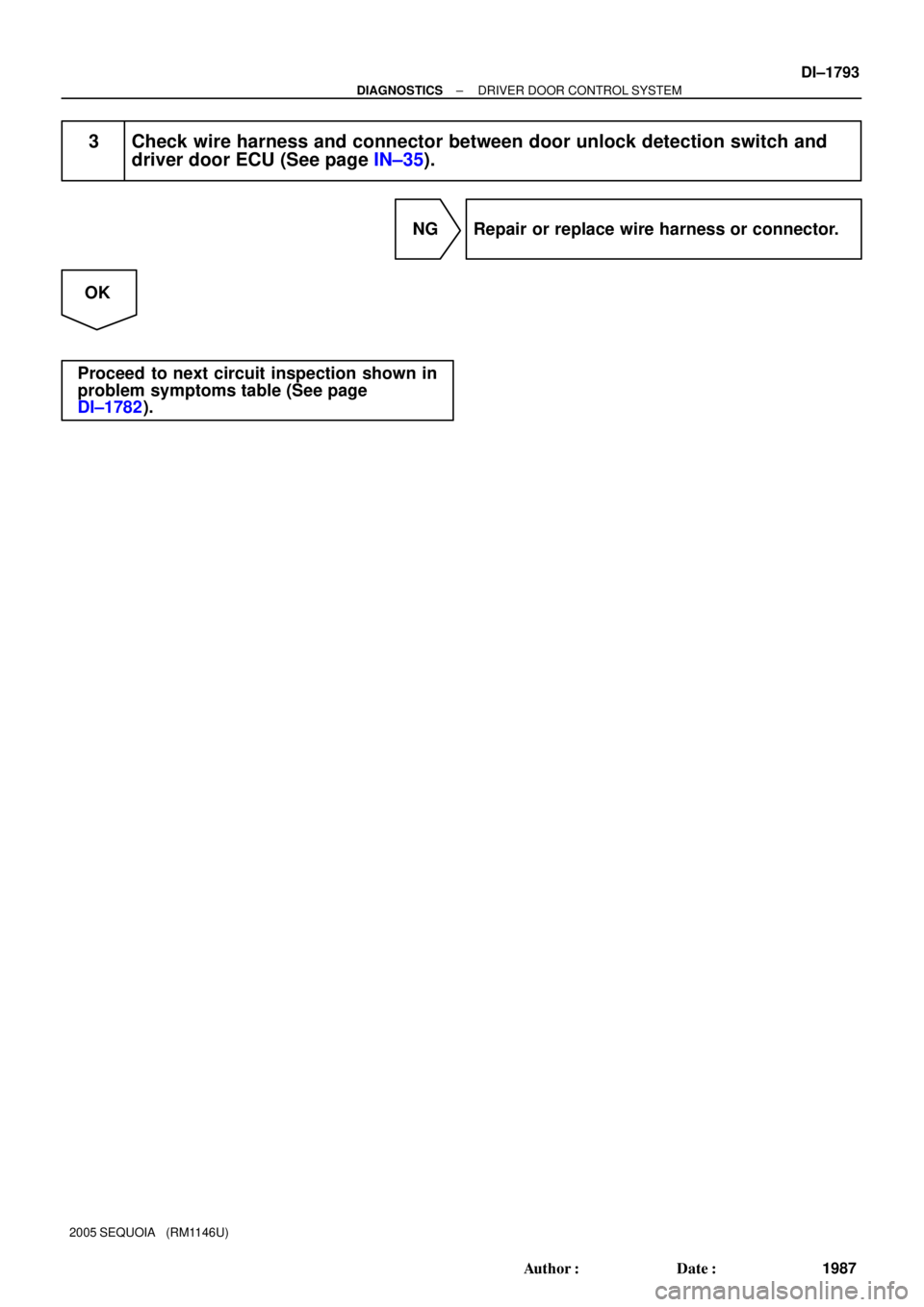
3 Check wire harness and connector between door unlock detection switch and
driver door ECU (See page IN±35).
NG Repair or replace wire harness or connector.
OK
Proceed to next circuit inspection shown in
problem symptoms table (See page
DI±1782).
Page 1996 of 4323
I18710
D22
Driver Door ECU
D20
Door Key Lock and
Unlock SW Front LH
LSWE
KUL
KL 9
10
22 W±B
LG±R
LG±B 3
6
5 DI±1794
± DIAGNOSTICSDRIVER DOOR CONTROL SYSTEM
1988 Author�: Date�:
2005 SEQUOIA (RM1146U)
Door key lock and unlock switch circuit
CIRCUIT DESCRIPTION
The door key lock and unlock switch is built in the door lock motor. When the key is turned to the lock side,
terminal 5 of the switch is grounded and when the key is turned to the unlock side, terminal 6 of the switch
is grounded.
The door key lock and unlock switch can be checked using the DTC check (refer to DI±1904).
WIRING DIAGRAM
DI1PH±17
Page 1997 of 4323
± DIAGNOSTICSDRIVER DOOR CONTROL SYSTEM
DI±1795
1989 Author�: Date�:
2005 SEQUOIA (RM1146U)
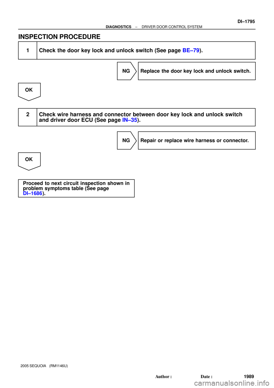
INSPECTION PROCEDURE
1 Check the door key lock and unlock switch (See page BE±79).
NG Replace the door key lock and unlock switch.
OK
2 Check wire harness and connector between door key lock and unlock switch
and driver door ECU (See page IN±35).
NG Repair or replace wire harness or connector.
OK
Proceed to next circuit inspection shown in
problem symptoms table (See page
DI±1686).
Page 2007 of 4323

I24364
D22
Driver Door ECU P4 Power Window
Control SW Rear RH
F18
Front Passenger Door ECU F10
Fusible Link Block
P3 Power Window Control
SW Rear LHE
B
L±O
5 W±B
PWR No. 4
R±L
WLSW U
D 3
5
24
BC1
A
J46L±O L±O 13
BC1 W±B
U
D5
2GR
2 1
BL±Y5
BA1L±YG
J30
L±Y
7
1G
8
1F
16
1F PWR No. 3 3
5
21 1
1L
9
1F
E
J6E
J7
E
J67
R±L
R±L
R±L
II1
LSW W±B
Battery
J8
J/CIE A W±B
BKW
85
B
BA1 13
W±B
BH ALTGR
2
1
3E
Power Main Relay
Instrument Panel J/B
J/C P9
Power
Window
Motor
Rear
RH P8
Power
Window
Motor
Rear
LH
7 4
5 N J/C
J/C
E J29
J47
± DIAGNOSTICSDRIVER DOOR CONTROL SYSTEM
DI±1805
1999 Author�: Date�:
2005 SEQUOIA (RM1146U)
Window lock switch circuit
CIRCUIT DESCRIPTION
The window lock switch circuit can be checked using the DTC check (refer to DI±1904).
The window lock switch is built in the driver door ECU. Voltage applied to the WLSW terminal of the driver
door ECU is shut off when the window lock switch is turned to the LOCK position. Thus the power main relay
stops power supply to the other power window control switches.
WIRING DIAGRAM
DI1PE±15