Page 176 of 4323

1.69 ± 1.71 mm (0.0665 ± 0.0673 in.)
1.72 ± 1.74 mm (0.0677 ± 0.0685 in.)
1.75 ± 1.77 mm (0.0689 �")
SS±34
± SERVICE SPECIFICATIONSSUSPENSION AND AXLE
176 Author�: Date�:
2005 SEQUOIA (RM1146U)
1.69 ± 1.71 mm (0.0665 ± 0.0673 in.)
1.72 ± 1.74 mm (0.0677 ± 0.0685 in.)
1.75 ± 1.77 mm (0.0689 ± 0.0697 in.)
1.78 ± 1.80 mm (0.0701 ± 0.0709 in.)
1.81 ± 1.83 mm (0.0713 ± 0.0720 in.)
1.84 ± 1.86 mm (0.0724 ± 0.0732 in.)
1.87 ± 1.89 mm (0.0736 ± 0.0744 in.)
1.90 ± 1.92 mm (0.0748 ± 0.0756 in.)
1.93 ± 1.95 mm (0.0760 ± 0.0768 in.)
1.96 ± 1.98 mm (0.0772 ± 0.0780 in.)
D i i i b i dj ti h thi k1.99 ± 2.01 mm (0.0783 ± 0.0791 in.)
F t diff ti l
Drive pinion bearing adjusting washer thickness2.02 ± 2.04 mm (0.0795 ± 0.0803 in.)Front differential2.05 ± 2.07 mm (0.0807 ± 0.0815 in.)
2.08 ± 2.10 mm (0.0819 ± 0.0827 in.)
2.11 ± 2.13 mm (0.0831 ± 0.0839 in.)
2.14 ± 2.16 mm (0.0843 ± 0.0850 in.)
2.17 ± 2.19 mm (0.0854 ± 0.0862 in.)
2.20 ± 2.22 mm (0.0866 ± 0.0874 in.)
2.23 ± 2.25 mm (0.0878 ± 0.0886 in.)
2.26 ± 2.28 mm (0.0890 ± 0.0898 in.)
2.29 ± 2.31 mm (0.0902 ± 0.0909 in.)
2.32 ± 2.34 mm (0.0913 ± 0.0921 in.)
A.D.D. sleeve fork to clutch sleeve clearance0.35 mm (0.0138 in.) or less
Differential case needle bearing press in depth0.3 ± 0.3 mm (0.012 ± 0.012 in.)
Axle shaft bearing backlash Maximum0.6 mm (0.024 in.)
RlhftAxle shaft deviation Maximum0.05 mm (0.0020 in.)Rear axle shaftShaft runoutMaximum2.0 mm (0.079 in.)
Flange runoutMaximum0.05 mm (0.0020 in.)
Page 181 of 4323

TORQUE SPECIFICATION
Part tightenedN´mkgf´cmft´lbf
TIRE PRESSURE MONITOR RECEIVER
Tire pre")
SS1KF±04
± SERVICE SPECIFICATIONSSUSPENSION AND AXLE
SS±39
181 Author�: Date�:
2005 SEQUOIA (RM1146U)
TORQUE SPECIFICATION
Part tightenedN´mkgf´cmft´lbf
TIRE PRESSURE MONITOR RECEIVER
Tire pressure monitor receiver set bolt7.57666 in.´lbf
TIRE PRESSURE MONITOR VALVE
Tire pressure monitor valve set nut4.04135 in.´lbf
FRONT AXLE
Hub nut11 01,15083
Tie rod end lock nut5556041
Steering knuckle x Brake caliper8082059
Steering knuckle x Dust cover1231,25090
Drive shaft lock nut1818513
Upper suspension arm x Upper ball joint2352,400173
Brake line clamp x Steering knuckle1051,10077
ABS speed sensor x Steering knuckle2828521
ABS speed sensor wire harness clamp x Steering knuckle8.08271 in.´lbf
ABS speed sensor wire harness clamp x Upper suspension arm8.08271 in.´lbf
FRONT DIFFERENTIAL
Drive pinion x companion flangeSee page SA±43
Differential front mounting cushion x Chassis frame1371,400101
Differential rear mounting cushion x Chassis frame8789064
Differential front mounting cushion x Differential1571,60011 6
Differential rear mounting cushion x Differential1081,10080
Ring gear x Differential case9798571
Differential carrier x Differential tube7880058
Differential carrier x Side bearing retainer6970051
Differential x Front propeller shaft7475054
A.D.D. clutch case x Differential7880058
A.D.D. clutch case x Differential tube7880058
A.D.D. actuator x A.D.D. clutch case2121015
Tube with wire harness assembly clamp x Differential carrier131309
Drain plug6566048
Filler plug3940029
FRONT SUSPENSION
Suspension support x Chassis frame6465047
Piston rod x Suspension support2525018
Lower suspension arm x Shock absorber1351,400100
Upper suspension arm x Chassis frame981,00072
Lower suspension arm x Chassis frame1301,32596
Lower suspension arm x Lower ball joint1591,62111 7
Power steering gear Left side nut
Center bolt
Right side bolt and nut130
165
1651,350
1,700
1,70096
122
122
Tie rod end x Lower ball joint9193067
No. 1, No. 2 spring bumper31 (23)315 (235)23 (17)
Lower suspension arm x Stabilizer bar link6970051
Page 2972 of 4323
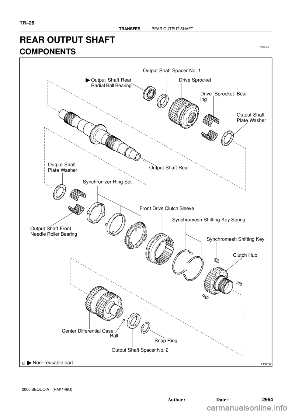
TR083±03
F19236
Output Shaft Rear
Radial Ball Bearing �Output Shaft Spacer No. 1
Output Shaft Front
Needle Roller Bearing
Synchronizer Ring Set
Front Drive Clutch Sleeve
� Non±reusable partCenter Differential Case
Ball
Snap Ring
Output Shaft Spacer No. 2Drive Sprocket
Drive Sprocket Bear-
ing
Output Shaft
Plate Washer
Output Shaft Rear Output Shaft
Plate Washer
Synchromesh Shifting Key Spring
Synchromesh Shifting Key
Clutch Hub
TR±26
± TRANSFERREAR OUTPUT SHAFT
2964 Author�: Date�:
2005 SEQUOIA (RM1146U)
REAR OUTPUT SHAFT
COMPONENTS
Page 2973 of 4323

DISASSEMBLY
1. INSPECT DRIVE SPROCKET THRUST CLEARANCE
Using a feeler gauge, mea")
TR0DH±01
F19276
F19277
F19278
F19279
± TRANSFERREAR OUTPUT SHAFT
TR±27
2965 Author�: Date�:
2005 SEQUOIA (RM1146U)
DISASSEMBLY
1. INSPECT DRIVE SPROCKET THRUST CLEARANCE
Using a feeler gauge, measure the thrust clearance of the drive
sprocket.
Standard clearance:
0.15 to 0.24 mm (0.0059 to 0.0094 in.)
Maximum clearance:
0.24 mm (0.0094 in.)
If the clearance exceeds the maximum, replace the drive
sprocket.
2. INSPECT DRIVE SPROCKET RADIAL CLEARANCE
Using a dial indicator, measure the radial clearance of the drive
sprocket.
Standard clearance:
0.01 to 0.06 mm (0.0004 to 0.0024 in.)
Maximum clearance:
0.06 mm (0.0024 in.)
If the clearance exceeds the maximum, replace the drive
sprocket, output shaft rear or needle roller bearing.
3. REMOVE CENTER DIFFERENTIAL CASE
(a) Using a snap ring expander, remove the snap ring.
(b) Remove the output shaft spacer No. 2 and ball.
(c) Remove the center differential case.
4. REMOVE CLUTCH HUB
Remove the clutch hub, output shaft front needle roller bearing
and output shaft plate washer.
Page 2976 of 4323

3. INSPECT HIGH AND LOW CLUTCH SLEEVE AND
GEAR SHIFT FORK NO. 2 CLEARANCE
(a) Using vernier calip")
F19285
F19288
F19287
TR±30
± TRANSFERREAR OUTPUT SHAFT
2968 Author�: Date�:
2005 SEQUOIA (RM1146U)
3. INSPECT HIGH AND LOW CLUTCH SLEEVE AND
GEAR SHIFT FORK NO. 2 CLEARANCE
(a) Using vernier calipers, measure the thickness of the gear
shift fork No. 2 claw.
Thickness: 10 mm (0.3937 in.)
(b) Using vernier calipers, measure the width of the groove
of the high and low clutch sleeve.
Width: 10.5 mm (0.4134 in.)
(c) Calculate the clearance between the high and low clutch
sleeve and gear shift fork No. 1.
Standard clearance:
0.26 to 0.84 mm (0.0102 to 0.0331 in.)
Maximum clearance:
0.84 mm (0.0331 in.)
If the clearance exceeds the maximum, replace the high and
low clutch sleeve or gear shift fork No. 2.
4. INSPECT CENTER DIFFERENTIAL CASE AND FRONT
DRIVE CLUTCH SLEEVE
(a) Check that the tip of the spline gear of the front drive
clutch sleeve is not worn.
(b) Install the front drive clutch sleeve to the center differen-
tial case and check that the front drive clutch sleeve
moves smoothly.
5. INSPECT CENTER DIFFERENTIAL CASE AND HIGH
AND LOW CLUTCH SLEEVE
(a) Check that the tip of the spline gear of the front drive
clutch sleeve is not worn.
(b) Install the front drive clutch sleeve to the center differen-
tial case and check that the front drive clutch sleeve
moves smoothly.
Page 2978 of 4323

(c) Install the output shaft plate washer and output shaft front
needle roller bearing to")
F19279
F19278
F19276
F19277
TR±32
± TRANSFERREAR OUTPUT SHAFT
2970 Author�: Date�:
2005 SEQUOIA (RM1146U)
(c) Install the output shaft plate washer and output shaft front
needle roller bearing to the output shaft rear.
(d) Install the clutch hub to the output shaft rear.
5. INSTALL CENTER DIFFERENTIAL CASE
(a) Install the center differential case to the output shaft rear.
(b) Install the ball and output shaft spacer No. 2 to the center
differential case.
(c) Using a snap ring expander, install the snap ring.
6. INSPECT DRIVE SPROCKET THRUST CLEARANCE
Using a feeler gauge, measure the thrust clearance of the drive
sprocket.
Standard clearance:
0.15 to 0.24 mm (0.0059 to 0.0094 in.)
Maximum clearance:
0.24 mm (0.0094 in.)
If the clearance exceeds the maximum, replace the drive
sprocket.
7. INSPECT DRIVE SPROCKET RADIAL CLEARANCE
Using a dial indicator, measure the radial clearance of the drive
sprocket.
Standard clearance:
0.01 to 0.06 mm (0.0004 to 0.0024 in.)
Maximum clearance:
0.06 mm (0.0024 in.)
If the clearance exceeds the maximum, replace the drive
sprocket, output shaft rear or needle roller bearing.
Page 2998 of 4323
PR05N±04
Z15303Matchmarks
Q07228
Matchmarks
F13575
Matchmarks
± PROPELLER SHAFTPROPELLER SHAFT ASSEMBLY (4WD)
PR±7
2990 Author�: Date�:
2005 SEQUOIA (RM1146U)
REMOVAL
1. REMOVE FRONT PROPELLER SHAFT
(a) Place matchmarks on the differential and propeller shaft
flange.
(b) Remove the 4 nuts, washers and bolts, and disconnect
the propeller shaft from the differential.
(c) Suspend the front side of the propeller shaft.
(d) Place matchmarks on the transfer and propeller shaft
flanges.
(e) Remove the 4 nuts and washers.
(f) Remove the propeller shaft from the transfer.
2. REMOVE REAR PROPELLER SHAFT
(a) Place matchmarks on the transfer and propeller shaft
flanges.
(b) Remove the 4 nuts and washers, and disconnect the pro-
peller shaft from the transfer.
(c) Suspend the front side of the propeller shaft.
(d) Place matchmarks on the differential and propeller shaft
flanges.
(e) Remove the 4 nuts, washers and bolts.
(f) Remove the propeller shaft from the differential.
Page 3000 of 4323

PR±9
2992 Author�: Date�:
2005 SEQUOIA (RM1146U)
INSTALLATION
1. INSTALL FRONT PROPE")
PR07N±02
Z15303
Matchmarks
F13575
Matchmarks
Q07228
Matchmarks
± PROPELLER SHAFTPROPELLER SHAFT ASSEMBLY (4WD)
PR±9
2992 Author�: Date�:
2005 SEQUOIA (RM1146U)
INSTALLATION
1. INSTALL FRONT PROPELLER SHAFT
(a) Align the matchmarks on the propeller shaft flanges and
differential, and connect the flanges with the 4 bolts,
washers and nuts.
(b) Torque the 4 bolts.
Torque: 74 N´m (750 kgf´cm, 54 ft´lbf)
(c) Align the matchmarks on the propeller shaft flanges and
transfer, and connect the flanges with the 4 washers and
nuts.
(d) Torque the 4 nuts.
Torque: 88 N´m (897 kgf´cm, 65 ft´lbf)
2. INSTALL REAR PROPELLER SHAFT
(a) Align the matchmarks on the propeller shaft flanges and
differential, and connect the flanges with the 4 bolts,
washers and nuts.
(b) Torque the 4 bolts.
Torque: 88 N´m (897 kgf´cm, 65 ft´lbf)
(c) Align the matchmarks on the propeller shaft flanges and
transfer, and connect the flanges with the 4 washers and
nuts.
(d) Torque the 4 nuts.
Torque: 88 N´m (897 kgf´cm, 65 ft´lbf)