Page 3046 of 4323
SA24Q±02
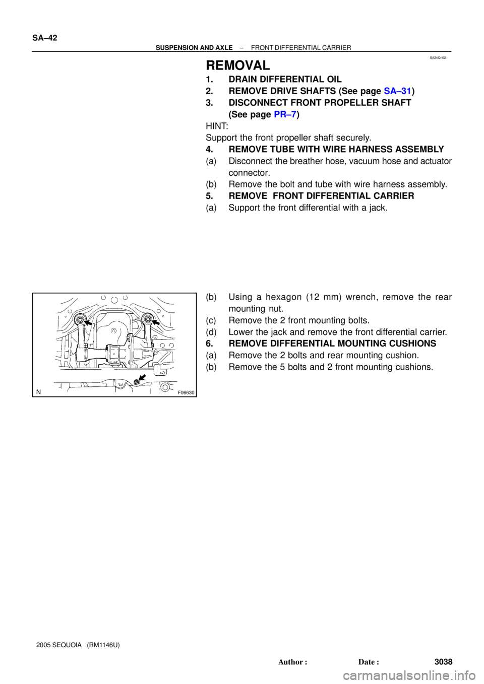
F06630
SA±42
± SUSPENSION AND AXLEFRONT DIFFERENTIAL CARRIER
3038 Author�: Date�:
2005 SEQUOIA (RM1146U)
REMOVAL
1. DRAIN DIFFERENTIAL OIL
2. REMOVE DRIVE SHAFTS (See page SA±31)
3. DISCONNECT FRONT PROPELLER SHAFT
(See page PR±7)
HINT:
Support the front propeller shaft securely.
4. REMOVE TUBE WITH WIRE HARNESS ASSEMBLY
(a) Disconnect the breather hose, vacuum hose and actuator
connector.
(b) Remove the bolt and tube with wire harness assembly.
5. REMOVE FRONT DIFFERENTIAL CARRIER
(a) Support the front differential with a jack.
(b) Using a hexagon (12 mm) wrench, remove the rear
mounting nut.
(c) Remove the 2 front mounting bolts.
(d) Lower the jack and remove the front differential carrier.
6. REMOVE DIFFERENTIAL MOUNTING CUSHIONS
(a) Remove the 2 bolts and rear mounting cushion.
(b) Remove the 5 bolts and 2 front mounting cushions.
Page 3047 of 4323

SA23N±04
R12683
SST
FA1158
F06631
± SUSPENSION AND AXLEFRONT DIFFERENTIAL CARRIER
SA±43
3039 Author�: Date�:
2005 SEQUOIA (RM1146U)
DISASSEMBLY
1. CHECK COMPANION FLANGE R")
W00493
30 mm (1.18 in.)
SA23N±04
R12683
SST
FA1158
F06631
± SUSPENSION AND AXLEFRONT DIFFERENTIAL CARRIER
SA±43
3039 Author�: Date�:
2005 SEQUOIA (RM1146U)
DISASSEMBLY
1. CHECK COMPANION FLANGE RUNOUT
Using a dial indicator, measure the vertical and lateral runout of
the companion flange.
Maximum runout: 0.10 mm (0.0039 in.)
If the runout exceeds the maximum, replace the companion
flange.
2. CHECK RING GEAR BACKLASH
Using SST and a dial indicator, measure the ring gear backlash.
SST 09564±32011
Backlash: 0.1 ± 0.18 mm (0.0039 ± 0.0071 in.)
HINT:
Measure at 3 or more points on the circumference of the ring
gear.
If the backlash is not within the specified value, adjust the side
bearing preload or repair as necessary.
3. MEASURE DRIVE PINION PRELOAD
Using a torque wrench, measure the preload using the back-
lash between the drive pinion and ring gear.
Preload (at starting):
0.6 ± 1.0 N´m (6 ± 10 kgf´cm, 5.2 ± 8.7 in.´lbf)
4. CHECK TOTAL PRELOAD
Using a torque wrench, measure the total preload with the teeth
of the drive pinion and ring gear in contact.
Total preload (at starting):
Drive pinion preload plus 0.4 ± 0.6 N´m (4 ± 6 kgf´cm,
3.5 ± 5.2 in.´lbf)
If necessary, disassemble and inspect the differential.
5. REMOVE A.D.D. ACTUATOR
(a) Remove the 4 bolts.
(b) Using a hammer handle, remove the actuator.
Page 3048 of 4323

6. REMOVE DIFFERENTIAL TUBE
(a) Using a torx so")
R13208
R13209
SST
R13197
SST
SA2349
SST
R11391
SST SA±44
± SUSPENSION AND AXLEFRONT DIFFERENTIAL CARRIER
3040 Author�: Date�:
2005 SEQUOIA (RM1146U)
6. REMOVE DIFFERENTIAL TUBE
(a) Using a torx socket (E14), remove the 4 torx bolts.
(b) Using a plastic hammer, tap on the differential tube to re-
move it.
(c) Remove the sleeve.
(d) Remove the O±ring from the differential tube.
7. REMOVE CLUTCH CASE
(a) Using a torx socket (E14), remove the 2 torx bolts.
(b) Using a plastic hammer, tap on the clutch case to remove
it.
8. REMOVE SIDE OIL SEAL
Using SST, remove the side oil seal.
SST 09308±00010
9. REMOVE INTERMEDIATE SHAFT NO. 1
(a) Using SST, remove the intermediate shaft No. 1.
SST 09350±20015 (09369±20040), 09950±40011
(09951±04010, 09952±04010, 09953±04020,
09954±04010, 09955±04011, 09957±04010,
09958±04011)
(b) Remove the snap ring.
10. REMOVE COMPANION FLANGE
(a) Using a chisel and hammer, unstake the nut.
(b) Using SST to hold the flange, remove the nut.
SST 09330±00021
(c) Using SST, remove the companion flange.
SST 09950±30012 (09951±03010, 09953±03010,
09954±03010, 09955±03030, 09956±03020)
Page 3049 of 4323
SA2348
SST
Z00641
SST
W04006
R02482
SST
R13226
± SUSPENSION AND AXLEFRONT DIFFERENTIAL CARRIER
SA±45
3041 Author�: Date�:
2005 SEQUOIA (RM1146U)
11. REMOVE OIL SEAL AND OIL SLINGER
(a) Using SST, remove the oil seal.
SST 09308±10010
(b) Remove the oil slinger.
12. REMOVE REAR BEARING AND BEARING SPACER
(a) Using SST, remove the rear bearing from the drive pinion.
SST 09556±22010
(b) Remove the bearing spacer.
13. REMOVE SIDE BEARING RETAINER
Remove the 10 bolts and tap out the retainer with a plastic ham-
mer.
14. REMOVE DIFFERENTIAL CASE ASSEMBLY
15. REMOVE DRIVE PINION FROM DIFFERENTIAL CAR-
RIER
16. REMOVE DRIVE PINION FRONT BEARING
Using SST and a press, remove the bearing and washer from
the drive pinion.
SST 09950±00020
HINT:
If the drive pinion or ring gear is damaged, replace them as a
set.
17. REMOVE DRIVE PINION BEARING OUTER RACES
(a) Using a brass bar and hammer, remove the front bearing
outer race.
Page 3050 of 4323

(b) Using SST, remov")
R13210
SST
R13211F14774
SSTSST
R13213
SSTSST
FA1998
Matchmarks
R11392
SST
SST SA±46
± SUSPENSION AND AXLEFRONT DIFFERENTIAL CARRIER
3042 Author�: Date�:
2005 SEQUOIA (RM1146U)
(b) Using SST, remove the rear bearing outer race.
SST 09502±12010, 09612±65014 (09612±01020,
09612±01050)
18. REMOVE SIDE BEARING OUTER RACES
HINT:
�Measure the plate washer thickness and note it down.
�Tag the bearing outer races to show the location for reas-
sembling.
(a) Using SST and a press, remove the plate washer and out-
er race from the bearing retainer.
SST 09950±60010 (09951±00650),
09950±70010 (09951±07150)
(b) Using SST and a press, remove the plate washer and out-
er race from the differential carrier.
SST 09950±60010 (09951±00650),
09950±70010 (09951±07150)
19. REMOVE RING GEAR
(a) Place matchmarks on the ring gear and differential case.
(b) Using a screwdriver and hammer, unstake the 5 lock
plates.
(c) Remove the 10 bolts and 5 lock plates.
(d) Using a plastic hammer, tap on the ring gear to separate
it from the differential case.
20. REMOVE SIDE BEARINGS
Using SST, remove the 2 side bearings from the differential
case.
SST 09950±40011 (09951±04010, 09952±04010,
09953±04020, 09954±04010, 09955±04061,
09957±04010, 09958±04011),
09950±60010 (09951±00480)
HINT:
Fix the claws of SST to the notch in the differential case.
Page 3051 of 4323
RA0997
SA0353
± SUSPENSION AND AXLEFRONT DIFFERENTIAL CARRIER
SA±47
3043 Author�: Date�:
2005 SEQUOIA (RM1146U)
21. DISASSEMBLE DIFFERENTIAL CASE ASSEMBLY
(a) Using a pin punch and hammer, remove the straight pin.
(b) Remove the pinion shaft, 2 pinion gears, pinion gear
thrust washers, side gears and side gear thrust washers
from the differential case.
22. REMOVE BEARINGS
Using a brass bar and hammer, remove the 2 bearings.
Page 3052 of 4323
SA24R±02
R04465
SST Socket Wrench
R04348
SST
Z03857
R13199
SST
R13422
SA±48
± SUSPENSION AND AXLEFRONT DIFFERENTIAL CARRIER
3044 Author�: Date�:
2005 SEQUOIA (RM1146U)
REPLACEMENT
1. REPLACE COMPANION FLANGE DUST DEFLECTOR,
IF NECESSARY
(a) Using SST, a socket wrench and a press, remove the dust
deflector.
SST 09950±00020
(b) Using SST and a press, install a new dust deflector.
SST 09636±20010
2. REPLACE INTERMEDIATE SHAFT NO. 2, IF NEC-
ESSARY
(a) Remove the clutch hub.
(1) Using a snap ring expander, remove the snap ring.
(2) Remove the clutch hub from the intermediate shaft
No. 2.
(b) Remove the oil seal.
Using SST, remove the oil seal from the tube.
SST 09308±00010
(c) Remove the intermediate shaft No. 2 from the tube.
(1) Using needle nose pliers, remove the snap ring.
(2) Remove the shaft from the tube.
(d) Remove the intermediate shaft No. 2 bearing.
(1) Using a snap ring expander, remove the snap ring.
Page 3053 of 4323
R13420
SST
R13421
SST
R13419
SST
5.5 ± 0.3 mm
(0.217 ± 0.012 in.)
SA0335
± SUSPENSION AND AXLEFRONT DIFFERENTIAL CARRIER
SA±49
3045 Author�: Date�:
2005 SEQUOIA (RM1146U)
(2) Using SST, a brass bar and press, remove the bear-
ing.
SST 09950±00020
(e) Install a new intermediate shaft No. 2 bearing.
(1) Using SST and a press, install a new bearing.
SST 09309±37010
(2) Using a snap ring expander, install a new snap ring.
(f) Install the intermediate shaft No. 2 to the tube.
(1) Install the shaft into the tube.
(2) Using needle nose pliers, install a new snap ring.
(g) Install a new oil seal.
(1) Using SST and a plastic hammer, install a new oil
seal.
SST 09223±15020
Oil seal drive in depth: 5.5 ± 0.3 mm (0.217 ± 0.012 in.)
(2) Coat the oil seal lip with MP grease.
(h) Install the clutch hub.
(1) Install the clutch hub to the shaft.
(2) Using a snap ring expander, install a new snap ring.