Page 2789 of 4323
SF0PB±02
B01689
12
When battery positive voltage is applied.
When battery positive voltage is cut off.Valve moves in direction.
Valve moves in direction.
± SFICAMSHAFT TIMING OIL CONTROL VALVE
SF±47
2781 Author�: Date�:
2005 SEQUOIA (RM1146U)
INSPECTION
INSPECT OIL CONTROL VALVE OPERATION
Connect the positive � lead to terminal 1 of the connector and
the negative � lead to terminal 2, then check the movement of
the valve.
If operation is not as specified, replace the oil control valve.
Page 2790 of 4323
SF1XL±01
SF±48
± SFICAMSHAFT TIMING OIL CONTROL VALVE
2782 Author�: Date�:
2005 SEQUOIA (RM1146U)
INSTALLATION
Installation is in the reverse order of removal. (See page SF±46)
Page 2825 of 4323

COOLANT
INSPECTION
HINT:
Check the coolant level when the engine is cold.
1. CHECK ENGINE COOLANT LEVEL AT RADIATOR RESE")
CO0IO±07
± COOLINGCOOLANT
CO±1
2817 Author�: Date�:
2005 SEQUOIA (RM1146U)
COOLANT
INSPECTION
HINT:
Check the coolant level when the engine is cold.
1. CHECK ENGINE COOLANT LEVEL AT RADIATOR RESERVOIR
The engine coolant level should be between the ºLOWº and ºFULLº lines at normal temperature
(20°C(68°F)).
If low, check for leaks and add ºToyota Super Long Life Coolantº or similar high quality ethylene glycol based
non±silicate, non±amine, non±nitrite, and non±borate coolant with long±life hybrid organic acid technology
up to the ºFULLº line.
2. CHECK ENGINE COOLANT QUALITY
(a) Remove the radiator cap.
CAUTION:
To avoid the danger of being burned, do not remove the radiator cap while the engine and radiator
are still hot, as fluid and steam can be blown out under pressure.
(b) There should not be any excessive deposits of rust or scale around the radiator cap or radiator filler
hole, and the coolant should be free from oil.
If excessively dirty, clean the coolant passages and replace the coolant.
(c) Reinstall the radiator cap.
Page 2827 of 4323
CO0IQ±10
D12721
Intake Air
Connector PS Air
Hose
No.2 Fan ShroudThrottle Body Cover
Fan Pulley
Drive Belt Fan with Fluid Coupling
A/C Compressor
A/C Compressor
Connector
Engine Under Cover (4WD) x 5Radiator Assembly
N´m (kgf´cm, ft´lbf): Specified torque
12 (120, 9)
49 (500, 36)
A/T Oil Cooler Hose
Clip
Clip
Engine Under Cover (2WD) Vacuum Hose
PCV Hose
Suction Hose
MAF Meter Wire
± COOLINGWATER PUMP
CO±3
2819 Author�: Date�:
2005 SEQUOIA (RM1146U)
WATER PUMP
COMPONENTS
Page 2828 of 4323
B17476
RH No.3 Timing Belt Cover
LH No.3 Timing Belt CoverNo.2 Timing Belt Cover
Camshaft Position
Sensor Connector
Engine Wire
Oil Cooler Pipe
Timing Belt
Fan Bracket Drive Belt Timing Pulley
Timing Belt Tensioner Dust Boot
N´m (kgf´cm, ft´lbf) : Specified torque Cover Plate
39 (400,29)
32 (330, 24)
16 (160, 12)
Water Bypass
Hose
Grommet
16 (160, 12)
245 (2,500, 181)
CO±4
± COOLINGWATER PUMP
2820 Author�: Date�:
2005 SEQUOIA (RM1146U)
Page 2831 of 4323
CO0UZ±05
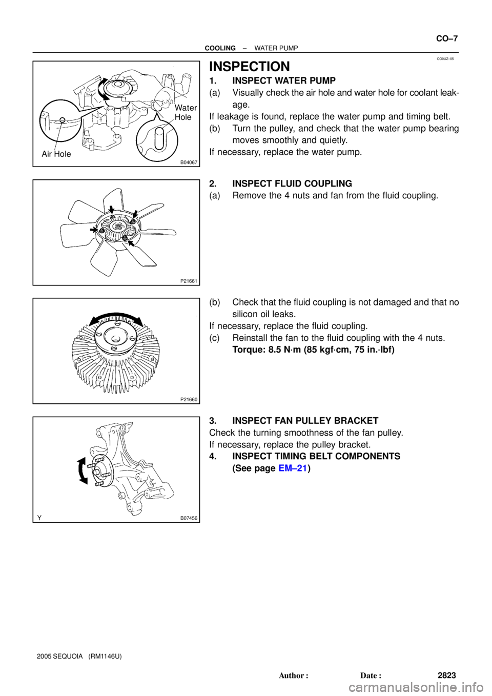
B04067Air HoleWa t e r
Hole
P21661
P21660
B07456
± COOLINGWATER PUMP
CO±7
2823 Author�: Date�:
2005 SEQUOIA (RM1146U)
INSPECTION
1. INSPECT WATER PUMP
(a) Visually check the air hole and water hole for coolant leak-
age.
If leakage is found, replace the water pump and timing belt.
(b) Turn the pulley, and check that the water pump bearing
moves smoothly and quietly.
If necessary, replace the water pump.
2. INSPECT FLUID COUPLING
(a) Remove the 4 nuts and fan from the fluid coupling.
(b) Check that the fluid coupling is not damaged and that no
silicon oil leaks.
If necessary, replace the fluid coupling.
(c) Reinstall the fan to the fluid coupling with the 4 nuts.
Torque: 8.5 N´m (85 kgf´cm, 75 in.´lbf)
3. INSPECT FAN PULLEY BRACKET
Check the turning smoothness of the fan pulley.
If necessary, replace the pulley bracket.
4. INSPECT TIMING BELT COMPONENTS
(See page EM±21)
Page 2832 of 4323

INSTALLATION
1. INSTALL WATER PUMP
(a) Install a n")
CO0IT±06
B04463
Connect
New O±Ring
B03030
Seal Width
2 ± 3 mm
New O±Ring
CO±8
± COOLINGWATER PUMP
2824 Author�: Date�:
2005 SEQUOIA (RM1146U)
INSTALLATION
1. INSTALL WATER PUMP
(a) Install a new O±ring to the water bypass pipe end.
(b) Apply soapy water to the O±ring.
(c) Connect the water pump to the water bypass pipe end.
(d) Install the water pump and a new gasket with the 5 bolts,
2 stud bolts and nut. Uniformly tighten the bolts, stud bolts
and nut in several passes.
Torque:
Bolt: 21 N´m (215 kgf´cm, 15 ft´lbf)
Stud bolt and nut: 18 N´m (185 kgf´cm, 13 ft´lbf)
2. INSTALL WATER INLET AND INLET HOUSING AS-
SEMBLY
(a) Remove any old packing (FIPG) material and be careful
not to drop any oil on the contact surfaces of the water in-
let housing and water pump.
�Using a razor blade and gasket scraper, remove all
the old packing (FIPG) material from the gasket sur-
faces and sealing groove.
�Thoroughly clean all components to remove all the
loose material.
�Using a non±residue solvent, clean both sealing
surfaces.
(b) Apply seal packing to the sealing groove of water inlet
housing as shown in the illustration.
Seal packing: Part No. 08826±00100 or equivalent
�Install a nozzle that has been cut to a 2 ± 3 mm (0.08
± 0.12 in.) opening.
�Parts must be assembled within 3 minutes of ap-
plication. Otherwise the material must be removed
and reapplied.
�Immediately remove nozzle from the tube and rein-
stall cap.
(c) Install a new O±ring to the water inlet housing.
(d) Apply soapy water on the O±ring.
(e) Attach the water inlet housing end to the front water by-
pass joint hole.
Page 2840 of 4323
CO1D2±01
B07246
Radiator Assembly
A/T Oil Cooler Hose
Engine Under Cover (4WD)Upper Radiator Hose
Lower Radiator Hose
x 5
N´m (kgf´cm, ft´lbf) : Specified torque
12 (120, 9)
No.1 Fan Shroud
No.2 Fan Shroud
Engine Under Cover (2WD)
Clip
Clip
CO±16
± COOLINGRADIATOR
2832 Author�: Date�:
2005 SEQUOIA (RM1146U)
COMPONENTS


 x 5")

Upper Radiator Hose
Lower Radiator Hose
x 5
N´m (kgf´cm, ft´lbf) : Specified torque
12 (120, 9)
No.1 Fan Shroud
No.2 F")