Page 2745 of 4323

B16499
Fulcrum
Length
30 cm
SST
B02714
CORRECT
WRONG
Delivery Pipe O±Ring
B04939
Delivery
Pipe
Intake
Manifold O±Ring
Grommet
Injector
Insulator
B17532
Quick Type
Disconnect
B11684
Quick Type
Push
Pull
± SFISFI SYSTEM
SF±3
2737 Author�: Date�:
2005 SEQUOIA (RM1146U)
(3) Using SST, tighten the union bolt to the specified
torque.
SST 09612±24014 (09617±24011)
Torque:
33 N´m (340 kgf´cm, 24 ft´lbf) for use with SST
39 N´m (400 kgf´cm, 29 ft´lbf)
HINT:
Use a torque wrench with a fulcrum length of 30 cm (11.81 in.).
(c) Observe the following precautions when removing or
installing the injectors.
(1) Never reuse the O±ring.
(2) When placing a new O±ring on the injector, take
care not to damage it in any way.
(3) Coat a new O±ring with spindle oil or gasoline be-
fore installing. Never use engine, gear or brake oil.
(d) Install the injector to the delivery pipe and intake manifold
as shown in the illustration.
Before installing the injector, apply spindle oil or gasoline
on the place where the delivery pipe or the intake man-
ifold touches the O±ring of the injector.
(e) Observe the following when disconnecting the fuel tube
connector (quick type):
(1) Check if there is any dirt in the pipe and around the
connector before disconnecting the fuel tube con-
nector. If necessary, clean the dirt away.
(2) Disconnect the fuel pipe clamp from the connector.
(3) Be sure to disconnect them by hand.
(4) When the connector and the pipe are stuck, push
and pull the connector. Then disconnect and pull it
out. Do not use any tools at this time.
(5) Check if there is any dirt or other foreign matter on
the seal surface of the disconnected pipe. If neces-
sary, clean the dirt away.
(6) Do not damage the disconnected pipe and connec-
tor and prevent intrusion of foreign objects by cover-
ing them with a plastic bag.
Page 2746 of 4323

B11683
Quick Type
Push
B12520
Quick Type
Pull
B17533
Quick Type
Install
B06584
Metallic Type
O±Ring Retainer Pipe
Nylon Tube
Housing
B09688
Metallic Type
SST
SF±4
± SFISFI SYSTEM
2738 Author�: Date�:
2005 SEQUOIA (RM1146U)
(f) Observe the following when connecting the fuel tube con-
nector (quick type):
(1) Check if there is any damage or foreign objects in
the connected part of the pipe.
(2) Match the axis of the connector with the axis of the
pipe, and push into the connector until a ºclickº
sound is heard. If the connection is tight, apply a
small amount of fresh engine oil on the tip of the
pipe.
(3) After finishing the connection, pull the pipe and the
connector to ensure it is secure.
(4) Check to make sure no fuel leak is present.
If the result is not specified, repair or replace.
(5) Install the fuel pipe clamp to the connector.
(6) Check to make sure no fuel leak is present.
If the result is not specified, repair or replace.
(g) Observe the following when disconnecting the fuel tube
connector (metallic type):
HINT:
The structure of the metallic connector is shown on the left.
(1) Check if there is any dirt in the pipe and around the
connector before disconnecting the fuel tube con-
nector. If necessary, clean the dirt away.
(2) Assemble SST to the connecting part, as shown in
the illustration.
SST 09268±21010
Page 2747 of 4323

B10036
Metallic Type
Pull Connector
B10485
Metallic Type
Push
B10485
Metallic Type
Pull
± SFISFI SYSTEM
SF±5
2739 Author�: Date�:
2005 SEQUOIA")
B10035
Metallic Type
SST
Insert Retainer
(at 4 places)
B10036
Metallic Type
Pull Connector
B10485
Metallic Type
Push
B10485
Metallic Type
Pull
± SFISFI SYSTEM
SF±5
2739 Author�: Date�:
2005 SEQUOIA (RM1146U)
(3) Turn the SST, align the retainers inside the connec-
tor with the SST chamfered parts and insert the SST
into the connector.
(4) While holding the SST, pull the connector towards
the SST to put the retainers on the SST chamfered
parts.
(5) Slide the SST and connector together towards the
fuel tube assembly.
(h) Observe the following when connecting the fuel tube con-
nector (metallic type):
(1) Check if there is any damage or foreign objects in
the connected part of the pipe.
(2) Match the axis of the connector with the axis of the
pipe, and push into the connector until a ºclickº
sound is heard. If the connection is tight, apply a
small amount of fresh engine oil on the tip of the
pipe.
(3) After finishing the connection, pull the pipe and the
connector to ensure it is secure.
(4) Check to make sure no fuel leak is present.
If the result is not specified, repair or replace.
(i) Observer the following when handling the nylon tube:
(1) Pay attention not to turn the connected part of the
nylon tube and the quick connector with tube when
connecting them.
(2) Pay attention not to kink the nylon tube.
(3) Do not remove the nylon tube.
(4) Do not close the piping with the nylon tube by bend-
ing it.
Page 2757 of 4323
B17610
Ohmmeter
SF131±03
B17611Battery 1 2
± SFIFUEL PUMP
SF±15
2749 Author�: Date�:
2005 SEQUOIA (RM1146U)
INSPECTION
1. INSPECT FUEL PUMP RESISTANCE
Using an ohmmeter, measure the resistance between the ter-
minals.
Resistance: 0.2 to 3.0 W at 20°C (68°F)
If the resistance is not as specified, replace the fuel pump.
2. INSPECT FUEL PUMP OPERATION
(a) Connect the lead wire to the fuel pump.
(b) Connect the positive (+) lead from the battery to terminal
1 of the connector, and the negative (±) lead to terminal
2. Check that the fuel pump operates.
NOTICE:
�These tests must be done quickly (within 10 seconds)
to prevent the coil from burning out.
�Keep the fuel pump as far away from the battery as
possible.
�Always do switching on the battery side.
If operation is not as specified, replace the fuel pump and/or
read wire.
(c) Disconnect the lead wire to the fuel pump.
Page 2758 of 4323
SF1XF±01
B17549
B17548
B17609
B17546
B17542
SF±16
± SFIFUEL PUMP
2750 Author�: Date�:
2005 SEQUOIA (RM1146U)
REASSEMBLY
1. REMOVE FUEL SUCTION PLATE NO.2
(a) Install the 2 springs and suction plate No.2 to the suction
plate No.1.
(b) Using a needle±nose pliers, install the 2 new E±rings to
the suction plate No.2.
2. INSTALL FUEL PUMP
(a) Apply a light coat of gasoline or spindle oil to a new O±
ring, and install it to the fuel pump.
(b) Connect the fuel pump harness connector to the fuel
pump.
(c) Install the fuel pump with the suction filter to the fuel filter.
3. INSTALL FUEL FILTER
Install the fuel filter to the fuel sub±tank.
Page 2786 of 4323
SF0P8±03
B12806
Ohmmeter SF±44
± SFICAMSHAFT TIMING OIL CONTROL VALVE
2778 Author�: Date�:
2005 SEQUOIA (RM1146U)
CAMSHAFT TIMING OIL CONTROL
VA LV E
ON±VEHICLE INSPECTION
(a) Remove the throttle body cover.
(b) Remove the intake air connector.
(c) Disconnect the oil control valve connector.
(d) Using an ohmmeter, measure the resistance between the
terminals.
Resistance: 6.9 to 7.9 W at 20°C (68°F)
If the resistance is not as specified, replace the valve.
(e) Reconnect the oil control valve connector.
(f) Reinstall the intake air connector.
(g) Reinstall the throttle body cover.
Page 2787 of 4323
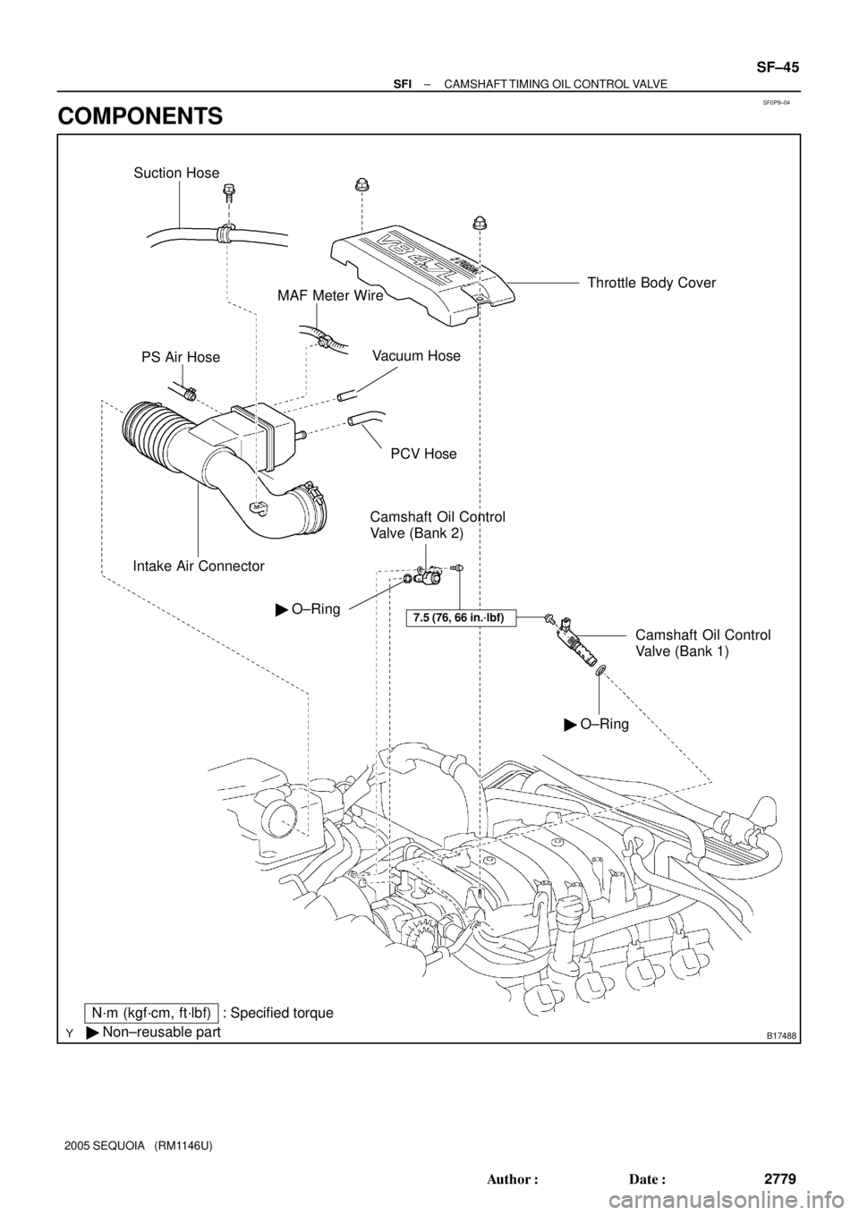
SF0P9±04
B17488
Throttle Body Cover
PS Air Hose
Intake Air Connector
Suction Hose
MAF Meter Wire
PCV Hose
Vacuum Hose
Camshaft Oil Control
Valve (Bank 2)
N´m (kgf´cm, ft´lbf)
� Non±reusable part� O±Ring
: Specified torque� O±Ring
Camshaft Oil Control
Valve (Bank 1)
7.5 (76, 66 in.´lbf)
± SFICAMSHAFT TIMING OIL CONTROL VALVE
SF±45
2779 Author�: Date�:
2005 SEQUOIA (RM1146U)
COMPONENTS
Page 2788 of 4323
SF1XK±01
B01688
SF±46
± SFICAMSHAFT TIMING OIL CONTROL VALVE
2780 Author�: Date�:
2005 SEQUOIA (RM1146U)
REMOVAL
1. REMOVE THROTTLE BODY COVER
2. REMOVE INTAKE AIR CONNECTOR
3. REMOVE CAMSHAFT TIMING OIL CONTROL VALVE
(a) Disconnect the 2 camshaft oil control valve connectors.
(b) Remove the bolt, camshaft oil control valve and O±ring.
Torque: 7.5 N´m (76 kgf´cm, 66 in.´lbf)
(c) Remove the O±ring from the each camshaft oil control
valve.
HINT:
At the time of installation, please refer to the following items.
Use a new O±rings.