Page 3239 of 4323
SR01V±10
R07281
Normal Abnormal SR±4
± STEERINGPOWER STEERING FLUID
3231 Author�: Date�:
2005 SEQUOIA (RM1146U)
POWER STEERING FLUID
BLEEDING
1. CHECK FLUID LEVEL (See page SR±5)
2. JACK UP FRONT OF VEHICLE AND SUPPORT IT
WITH STANDS
3. TURN STEERING WHEEL
With the engine stopped, turn the wheel slowly from lock to lock
several times.
4. LOWER VEHICLE
5. START ENGINE
Run the engine at idle for a few minutes.
6. TURN STEERING WHEEL
(a) With the engine idling, turn the wheel left or right to the full
lock position and keep it there for 2 to 3 seconds, then turn
the wheel to the opposite full lock position and keep it
there for 2 to 3 seconds.
(b) Repeat (a) several times.
7. STOP ENGINE
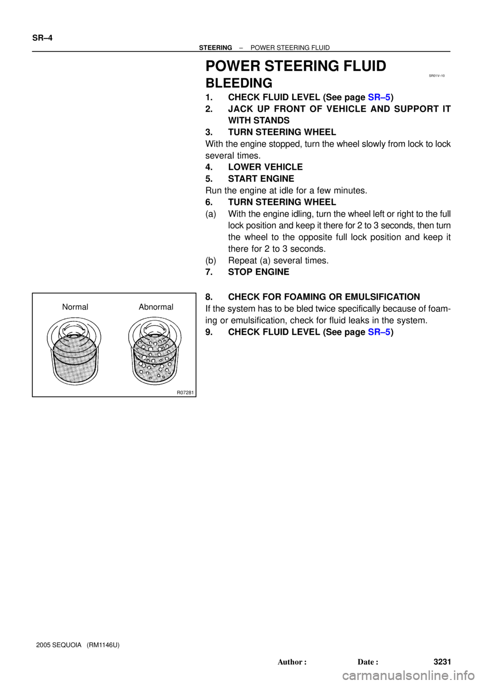
8. CHECK FOR FOAMING OR EMULSIFICATION
If the system has to be bled twice specifically because of foam-
ing or emulsification, check for fluid leaks in the system.
9. CHECK FLUID LEVEL (See page SR±5)
Page 3240 of 4323
R00427
HOT
COLD
SR01W±10
R07281
Normal Abnormal
R10552
5 mm (0.20 in.)
or less
Engine Idling Engine Stopped
± STEERINGPOWER STEERING FLUID
SR±5
3232 Author�: Date�:
2005 SEQUOIA (RM1146U)
INSPECTION
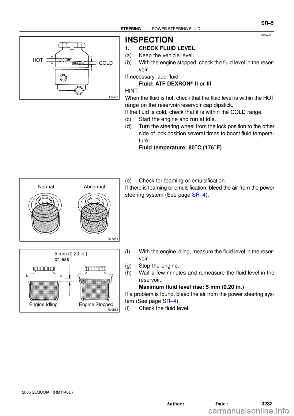
1. CHECK FLUID LEVEL
(a) Keep the vehicle level.
(b) With the engine stopped, check the fluid level in the reser-
voir.
If necessary, add fluid.
Fluid: ATF DEXRON® II or III
HINT:
When the fluid is hot, check that the fluid level is within the HOT
range on the reservoir/reservoir cap dipstick.
If the fluid is cold, check that it is within the COLD range.
(c) Start the engine and run at idle.
(d) Turn the steering wheel from the lock position to the other
side of lock position several times to boost fluid tempera-
ture.
Fluid temperature: 80°C (176°F)
(e) Check for foaming or emulsification.
If there is foaming or emulsification, bleed the air from the power
steering system (See page SR±4).
(f) With the engine idling, measure the fluid level in the reser-
voir.
(g) Stop the engine.
(h) Wait a few minutes and remeasure the fluid level in the
reservoir.
Maximum fluid level rise: 5 mm (0.20 in.)
If a problem is found, bleed the air from the power steering sys-
tem (See page SR±4).
(i) Check the fluid level.
Page 3241 of 4323
F13254
INOUTAttachment
Pressure Feed Tube
SST
Z15498
Oil
Reservoir
PS Vane
Pump PS Gear
SST Closed
Z15499
Oil
Reservoir
PS Vane
Pump PS Gear
SST Open SR±6
± STEERINGPOWER STEERING FLUID
3233 Author�: Date�:
2005 SEQUOIA (RM1146U)
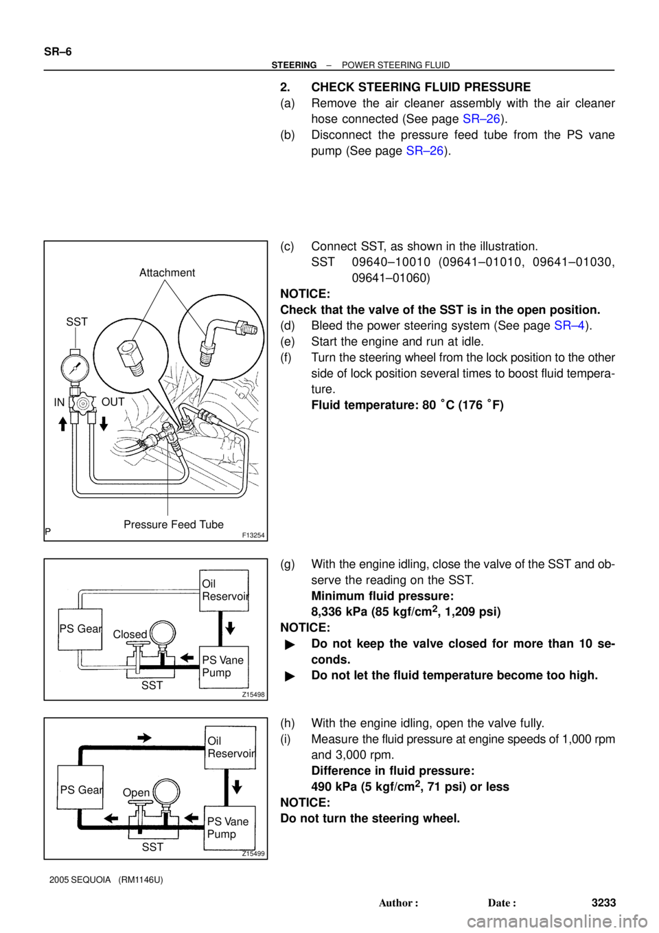
2. CHECK STEERING FLUID PRESSURE
(a) Remove the air cleaner assembly with the air cleaner
hose connected (See page SR±26).
(b) Disconnect the pressure feed tube from the PS vane
pump (See page SR±26).
(c) Connect SST, as shown in the illustration.
SST 09640±10010 (09641±01010, 09641±01030,
09641±01060)
NOTICE:
Check that the valve of the SST is in the open position.
(d) Bleed the power steering system (See page SR±4).
(e) Start the engine and run at idle.
(f) Turn the steering wheel from the lock position to the other
side of lock position several times to boost fluid tempera-
ture.
Fluid temperature: 80 °C (176 °F)
(g) With the engine idling, close the valve of the SST and ob-
serve the reading on the SST.
Minimum fluid pressure:
8,336 kPa (85 kgf/cm
2, 1,209 psi)
NOTICE:
�Do not keep the valve closed for more than 10 se-
conds.
�Do not let the fluid temperature become too high.
(h) With the engine idling, open the valve fully.
(i) Measure the fluid pressure at engine speeds of 1,000 rpm
and 3,000 rpm.
Difference in fluid pressure:
490 kPa (5 kgf/cm
2, 71 psi) or less
NOTICE:
Do not turn the steering wheel.
Page 3242 of 4323
Z15500
Oil
Reservoir
PS Vane
Pump PS Gear
SST Open Lock Position
± STEERINGPOWER STEERING FLUID
SR±7
3234 Author�: Date�:
2005 SEQUOIA (RM1146U)
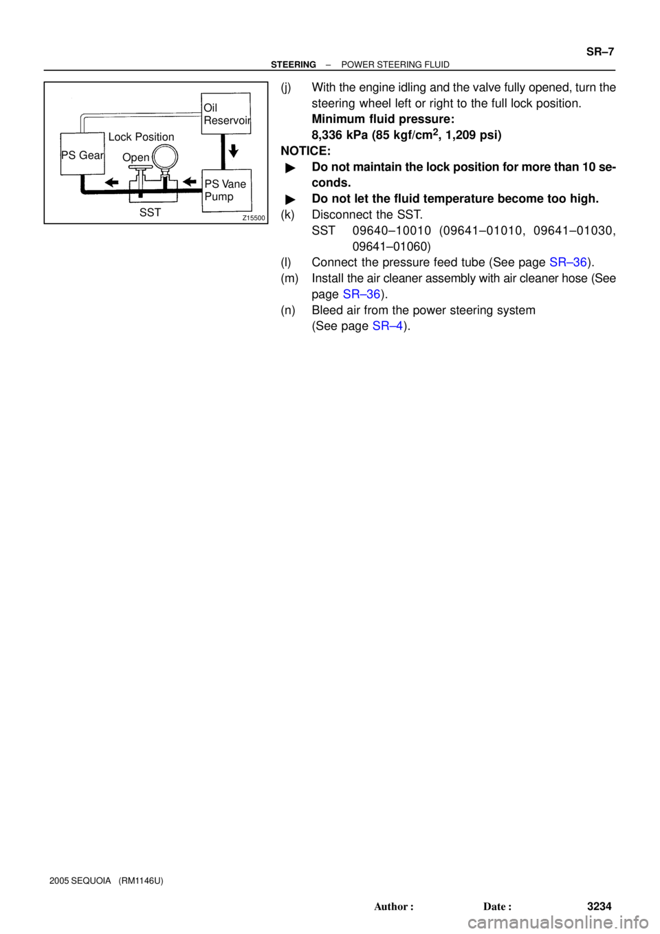
(j) With the engine idling and the valve fully opened, turn the
steering wheel left or right to the full lock position.
Minimum fluid pressure:
8,336 kPa (85 kgf/cm
2, 1,209 psi)
NOTICE:
�Do not maintain the lock position for more than 10 se-
conds.
�Do not let the fluid temperature become too high.
(k) Disconnect the SST.
SST 09640±10010 (09641±01010, 09641±01030,
09641±01060)
(l) Connect the pressure feed tube (See page SR±36).
(m) Install the air cleaner assembly with air cleaner hose (See
page SR±36).
(n) Bleed air from the power steering system
(See page SR±4).
Page 3262 of 4323
F06720
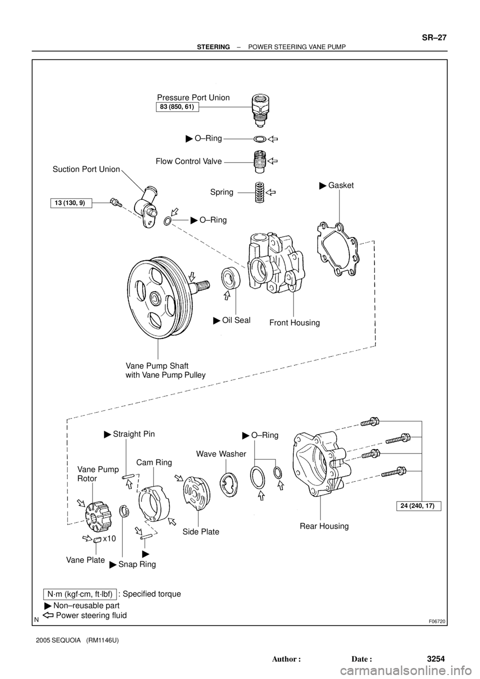
Pressure Port Union
83 (850, 61)
� O±Ring
Flow Control Valve
Spring
� O±Ring
Suction Port Union
13 (130, 9)
Vane Pump Shaft
with Vane Pump Pulley
� Oil Seal
Front Housing
� Gasket
24 (240, 17)
Rear Housing
� O±Ring
Wave Washer
Side Plate
Cam Ring
� Straight Pin
Vane Pump
Rotor
�
� Snap Ring x10Vane Plate
N´m (kgf´cm, ft´lbf): Specified torque
� Non±reusable part
Power steering fluid
± STEERINGPOWER STEERING VANE PUMP
SR±27
3254 Author�: Date�:
2005 SEQUOIA (RM1146U)
Page 3266 of 4323

R13897Inscribed Mark
W04759
F04865
Compressed Air
F04866Inscribed Mark
± STEERINGPOWER STEERING VANE PUMP
SR±31
3258 Author�: Date�:
2005 SEQUOIA (RM1146U)
If it is more than the maximum, replace the plate and/or rotor
with the one having the same mark stamped on the cam ring.
Inscribed mark: 1, 2, 3, 4 or None
HINT:
There are 5 vane plate lengths with the following rotor and cam
ring marks:
Rotor and cam
ring markVane plate part
numberVane plate length
mm (in.)
None44345±0401014.999±15.001
(0.59051±0.59059)
144345±0402014.997±14.999
(0.59043±0.59051)
244345±0403014.995±14.997
(0.59035±0.59043)
344345±0404014.993±14.995
(0.59027±0.59035)
444345±0405014.991±14.993
(0.59020±0.59027)
3. INSPECT FLOW CONTROL VALVE
(a) Coat the valve with power steering fluid and check that it
falls smoothly into the valve hole under its own weight.
(b) Check the flow control valve for leakage.
Close one of the holes and apply compressed air 392 to
490 kPa (4 to 5 kgf/cm
2, 57 to 71 psi) into the opposite
side, and confirm that air does not come out from the end
holes.
If necessary, replace the valve with the one having the same let-
ter inscribed on the front housing.
Inscribed mark: A, B, C, D, E or F
Page 3268 of 4323
SR0RG±09
F01511
Vinyl Tape
F06727
Press
SST
Oil Seal
SST
± STEERINGPOWER STEERING VANE PUMP
SR±33
3260 Author�: Date�:
2005 SEQUOIA (RM1146U)
REPLACEMENT
NOTICE:
When using a vise, do not overtighten it.
IF NECESSARY, REPLACE OIL SEAL
(a) Using a screwdriver with vinyl tape wound around its tip,
remove the oil seal.
NOTICE:
Be careful not to damage the front housing.
(b) Coat a new oil seal lip with power steering fluid.
(c) Using SST, press in the oil seal.
SST 09950±60010 (09951±00330),
09950±70010 (09951±07100)
NOTICE:
Make sure to install the oil seal in the correct direction.
Page 3269 of 4323
SR0V8±04
F04809
Inscribed Mark
F04810
Round End
F01507
SR±34
± STEERINGPOWER STEERING VANE PUMP
3261 Author�: Date�:
2005 SEQUOIA (RM1146U)
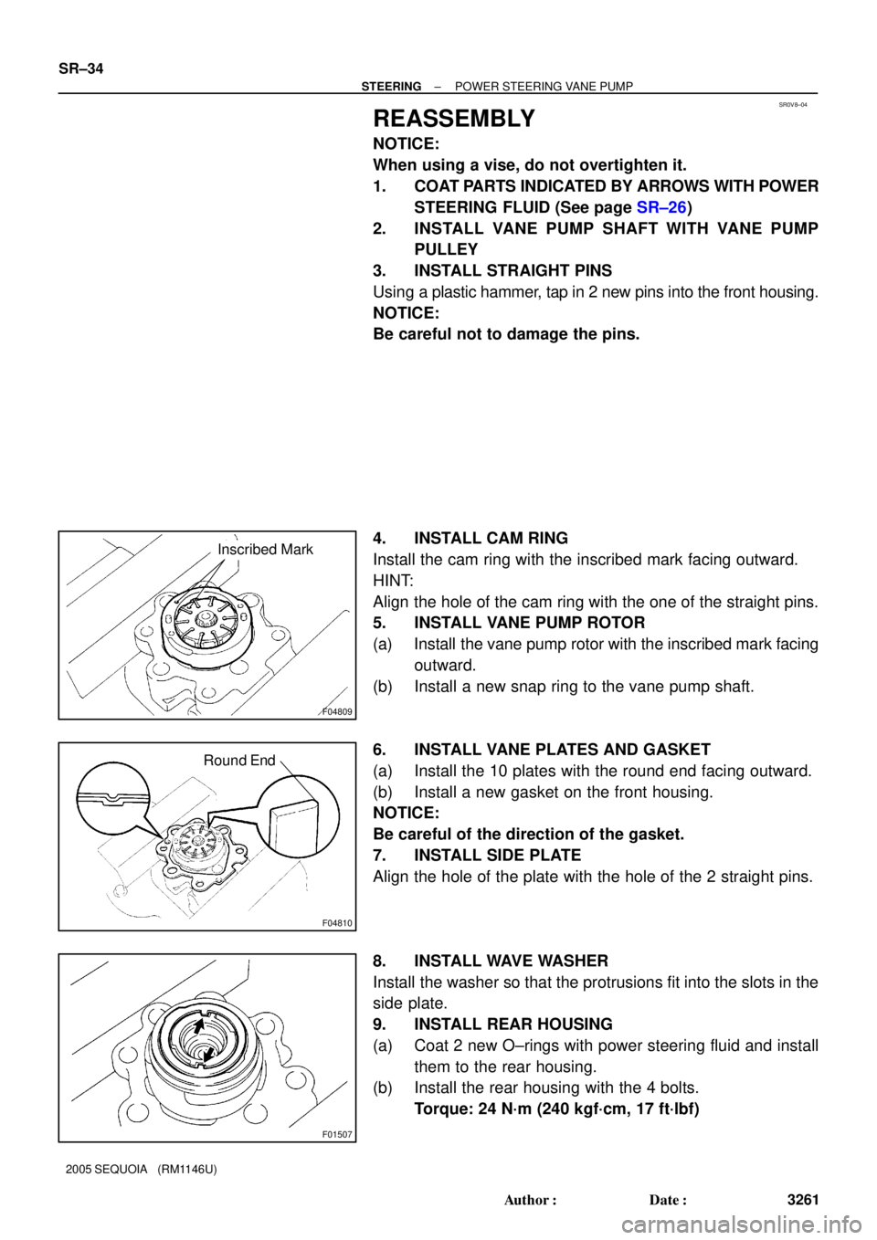
REASSEMBLY
NOTICE:
When using a vise, do not overtighten it.
1. COAT PARTS INDICATED BY ARROWS WITH POWER
STEERING FLUID (See page SR±26)
2. INSTALL VANE PUMP SHAFT WITH VANE PUMP
PULLEY
3. INSTALL STRAIGHT PINS
Using a plastic hammer, tap in 2 new pins into the front housing.
NOTICE:
Be careful not to damage the pins.
4. INSTALL CAM RING
Install the cam ring with the inscribed mark facing outward.
HINT:
Align the hole of the cam ring with the one of the straight pins.
5. INSTALL VANE PUMP ROTOR
(a) Install the vane pump rotor with the inscribed mark facing
outward.
(b) Install a new snap ring to the vane pump shaft.
6. INSTALL VANE PLATES AND GASKET
(a) Install the 10 plates with the round end facing outward.
(b) Install a new gasket on the front housing.
NOTICE:
Be careful of the direction of the gasket.
7. INSTALL SIDE PLATE
Align the hole of the plate with the hole of the 2 straight pins.
8. INSTALL WAVE WASHER
Install the washer so that the protrusions fit into the slots in the
side plate.
9. INSTALL REAR HOUSING
(a) Coat 2 new O±rings with power steering fluid and install
them to the rear housing.
(b) Install the rear housing with the 4 bolts.
Torque: 24 N´m (240 kgf´cm, 17 ft´lbf)