Page 1814 of 4323

DID8S±01
/ /
/ /
COMBINATION METER SYSTEM Check Sheet
Inspector 's name:
Customer 's NameVIN
Production Date
Licence Plate No.
Date Vehicle
Brought InOdometer Readingkm
miles
Weather Conditions
When Problem
OccurredFrequency Problem Occurs
Weather
Outside temperature� Constantly � Sometimes ( times per day, month)
� Once only Date Problem First Occurred
� Fine � Cloudy � Rainy � Snowy
� Various/Others
� Hot � Warm � Cool
� Cold (Approx. 5F ( 5C))
Problem Symptom
Gauge
� Malfunction in speedometer
� Malfunction in tachometer
� Malfunction in engine coolant temperature receiver gauge
� Malfunction in fuel receiver gauge
� Entire combination meter does not operate
� Buzzer does not sound (Key reminder warning, Seat belt warning)
� Seat belt warning for driver's seat does not operate
Others
� Operating light control rheostat does not change light brightness
�
�
�
�
�
�
�
�
� Malfunction in oil pressure receiver gauge
� Malfunction in volt meter DI±1612
± DIAGNOSTICSCOMBINATION METER SYSTEM
1806 Author�: Date�:
2005 SEQUOIA (RM1146U)
CUSTOMER PROBLEM ANALYSIS CHECK
Page 1816 of 4323

PROBLEM SYMPTOMS TABLE
HINT:
Inspect the related ºFuseº and ºRelayº before confirming the su")
DID8U±01
DI±1614
± DIAGNOSTICSCOMBINATION METER SYSTEM
1808 Author�: Date�:
2005 SEQUOIA (RM1146U)
PROBLEM SYMPTOMS TABLE
HINT:
Inspect the related ºFuseº and ºRelayº before confirming the suspected area as shown in the table below.
MALFUNCTION SYSTEM:
SymptomSuspected AreaSee page
Entire combination meter does not operate.Refer to troubleshooting proceduresDI±1628
Operating light control rheostat does not change light brightness.Refer to troubleshooting proceduresDI±1645
Seat belt warning does not operate.Refer to troubleshooting proceduresDI±1650
Key reminder warning buzzer does not sound.
1. Multiplex communication system
2. Key unlock warning switch circuit
3. Door courtesy lamp switch circuit
4. Combination meter assyDI±1892
DI±1715
DI±1728
IN±35
METER GAUGES:
SymptomSuspected AreaSee page
Malfunction in speedometerRefer to troubleshooting proceduresDI±1632
Malfunction in tachometerRefer to troubleshooting proceduresDI±1636
Malfunction in fuel receiver gaugeRefer to troubleshooting proceduresDI±1640
Malfunction in engine coolant temperature receiver gaugeRefer to troubleshooting proceduresDI±1644
Malfunction in oil pressure receiver gaugeRefer to troubleshooting proceduresDI±1654
Malfunction in volt meterRefer to troubleshooting proceduresDI±1658
WARNING LIGHTS:
SymptomSuspected AreaSee page
Check engine warning light (MIL) does not come on.
1. ECM
2. Wire harness or connector
3. Combination meter assyDI±9
±
IN±35
Discharge warning light does not come on.
1. ECM
2. Wire harness or connector
3. Combination meter assyDI±9
±
IN±35
Brake warning light does not come on.
1. Skid control ECU
2. Wire harness or connector
3. Combination meter assyDI±895
±
IN±35
ABS warning light does not come on.
1. Skid control ECU
2. Wire harness or connector
3. Combination meter assyDI±895
±
IN±35
SRS warning light does not come on.
1. Airbag sensor assy
2. Wire harness or connector
3. Combination meter assyDI±1126
±
IN±35
Open door warning light does not come on.
1. Door courtesy light switch circuit
2. Wire harness or connector
3. Combination meter assy
4. Body ECUDI±1728
±
IN±35
IN±35
Fuel level warning light does not come on.
1. Refer to troubleshooting
2. Wire harness or connector
3. Combination meter assyDI±1640
±
IN±35
Low oil pressure warning light does not come on.
1. Low oil pressure warning switch
2. Wire harness or connector
3. Combination meter assyBE±55
±
IN±35
Page 1828 of 4323

DATA LIST / ACTIVE TEST
DATA LIST
According to the DATA LIST displayed by the hand±held tester,")
DID8X±01
DI±1626
± DIAGNOSTICSCOMBINATION METER SYSTEM
1820 Author�: Date�:
2005 SEQUOIA (RM1146U)
DATA LIST / ACTIVE TEST
DATA LIST
According to the DATA LIST displayed by the hand±held tester, you can read the values of the switches,
sensors, actuators and so on without part removal. Reading the DATA LIST as the first step of troubleshoot-
ing is one method to shorten labor time.
(a) Warm up the engine.
(b) Turn the ignition switch off.
(c) Connect the hand±held tester to the DLC3.
(d) Turn the ignition switch to the ON position.
(e) Operate the hand±held tester according to the steps on the display and select ºDATA LISTº.
METER:
ItemMeasurement Item /
Range (Display)Normal ConditionDiagnostic Note
SPEED METER
Vehicle Speed Meter /
Min.: 0 km/h (0 mph)
Max.: 255 km/h (158 mph)Almost the same as actual vehicle
speed (When driving)
TACHO METEREngine RPM /
Min.: 0 rpm Max.: 12,750 rpmAlmost the same as actual engine
speed (When engine is running)
FUEL GAUGEFuel Input /
Min.: 0 Max.: 255Tester indication changes accord-
ing to the fuel receiver gauge
angle.
LIGHT RHEOSTATLight Control Rheostat /
Min.: 0 Max.: 255Light control rheostat switch is
Dark (0) " Bright (255)
OIL GAUGEOil Gauge /
Min.: 0 Max.: 255Tester indication changes accord-
ing to the oil pressure receiver
gauge angle.
ODO/TRIP SWODO / TRIP
ODO/TRIP switch / ON/OFFON: Switch is pushed
OFF: Switch is released
Page 1857 of 4323
± DIAGNOSTICSCOMBINATION METER SYSTEM
DI±1655
1849 Author�: Date�:
2005 SEQUOIA (RM1146U)
INSPECTION PROCEDURE
HINT:
Start the inspection from step 1 when using the hand±held tester and start from step 3 when not using the
hand±held tester.
1 Perform active test by hand±held tester.
PREPARATION:
(a) Connect the hand±held tester to the DLC3.
(b) Turn the ignition switch ON, and push the hand±held tester main switch ON.
CHECK:
From the display on the tester, perform the ºACTIVE TESTº.
METER:
ItemTest DetailsDiagnostic Note
OIL PRESS METERHIGH, 3/4, 1/2, 1/4, LOW (OFF)Confirm that the vehicle is stopped and engine is
idling.
OK:
Oil pressure receiver gauge readings change according to hand±held tester operation.
NG Replace combination meter
(See page IN±35).
OK
Page 1858 of 4323

2 Read value of hand±held tester.
PREPARATION:
(a) Connect the hand±held tester to the DLC3.
(b)")
I01278
DI±1656
± DIAGNOSTICSCOMBINATION METER SYSTEM
1850 Author�: Date�:
2005 SEQUOIA (RM1146U)
2 Read value of hand±held tester.
PREPARATION:
(a) Connect the hand±held tester to the DLC3.
(b) Turn the ignition switch ON, and push the hand±held tester main switch ON.
CHECK:
Operate the hand±held tester according to the steps on the display and select ºDATA LISTº.
METER:
ItemMeasurement Item /
Range (Display)Normal ConditionDiagnostic Note
OIL GAUGEOil Gauge /
Min.: 0 Max.: 255Tester indication changes accord-
ing to the oil pressure receiver
gauge angle.
OK:
Oil pressure displayed on the tester is almost the same as the actual oil pressure.
OK Replace combination meter.
(See page IN±35)
NG
3 Inspect oil pressure sender gauge.
PREPARATION:
Disconnect the connector from the oil pressure sender.
CHECK:
(a) Check that no continuity exists between the terminal and
ground with the engine stopped.
(b) Check that continuity exists between the terminal and
ground with the engine running.
HINT:
Oil pressure should be over 24.5 kPa (0.25 kgf/cm
2, 3.55 psi).
OK:
When engine is stopped:
No continuity
When engine is running:
Continuity
NG Replace oil pressure sender gauge.
OK
Page 2843 of 4323
:
TEMPERATURE RANGE ANTICIPATED BEFORE NEXT OIL CHANGE5W±30°C °F
±20
±290
±1820
±740
460
1680
27100
38
LU0GV±05
B07230
Oil Pressure Gauge
Oil Pressure Switch")
B16233
Recommended Viscosity (SAE):
TEMPERATURE RANGE ANTICIPATED BEFORE NEXT OIL CHANGE5W±30°C °F
±20
±290
±1820
±740
460
1680
27100
38
LU0GV±05
B07230
Oil Pressure Gauge
Oil Pressure Switch
P08343
Adhesive
± LUBRICATIONOIL AND FILTER
LU±1
2835 Author�: Date�:
2005 SEQUOIA (RM1146U)
OIL AND FILTER
INSPECTION
1. CHECK ENGINE OIL QUALITY
Check the oil for deterioration, entry of water, discoloring or thin-
ning.
If the quality is visibly poor, replace the oil.
Oil grade:
API grade SL Energy±Conserving or ILSAC multi-
grade engine oil.
2. CHECK ENGINE OIL LEVEL
The oil level should be between the ºLº and ºFº marks on the dip-
stick.
If low, check for leakage and add oil up to the ºFº mark.
NOTICE:
Do not fill with engine oil above the ºFº mark.
3. REMOVE ENGINE UNDER COVER
4. REMOVE OIL PRESSURE SWITCH
5. INSTALL OIL PRESSURE GAUGE
6. WARM UP ENGINE
Allow the engine to warm up to normal operating temperature.
7. CHECK OIL PRESSURE
Oil pressure:
At idle29 kPa (0.3 kgf/cm2, 4.2 psi) or more
At 3,000 rpm294 ± 588 kPa (3.0 ± 6.0 kgf/cm2, 43 ± 85 psi)
8. REMOVE OIL PRESSURE GAUGE
9. REINSTALL OIL PRESSURE SWITCH
(a) Apply adhesive to 2 or 3 threads of the oil pressure switch.
Adhesive:
Part No. 08833±00080, THREE BOND 1344, LOCTITE
242 or equivalent
(b) Reinstall the oil pressure switch.
10. START ENGINE, AND CHECK FOR ENGINE OIL
LEAKS
11. REINSTALL ENGINE UNDER COVER
Page 2844 of 4323

REPLACEMENT
CAUTION:
�Prolonged and repeated contact with mineral oil will
result in the r")
LU0GW±07
B07231
B07232
SST
LU±2
± LUBRICATIONOIL AND FILTER
2836 Author�: Date�:
2005 SEQUOIA (RM1146U)
REPLACEMENT
CAUTION:
�Prolonged and repeated contact with mineral oil will
result in the removal of natural fats from the skin,
leading to dryness, irritation and dermatitis. In addi-
tion, used engine oil contains potentially harmful
contaminants which may cause skin cancer.
�Care should be taken, therefore, when changing en-
gine oil to minimize the frequency and length of time
your skin is exposed to used engine oil. Protective
clothing and gloves that cannot be penetrated by oil
should be worn. The skin should be thoroughly
washed with soap and water, or use water±less hand
cleaner, to remove any used engine oil. Do not use
gasoline, thinners, or solvents.
�In order to preserve the environment, used oil and
used oil filters must be disposed of only at desig-
nated disposal sites.
1. w/ Oil filter change:
REMOVE ENGINE UNDER COVER
2. DRAIN ENGINE OIL
(a) Remove the oil filler cap.
(b) Remove the oil drain plug and gasket, and drain the oil
into a container.
3. REPLACE OIL FILTER
(a) Using SST, remove the oil filter.
SST 09228±07501
(b) Clean the oil filter contact surface on the oil filter mount-
ing.
(c) Lubricate the filter rubber gasket with clean engine oil.
Page 2845 of 4323
B07233
B07234
SST
3/4 Turn
B07235
Front
± LUBRICATIONOIL AND FILTER
LU±3
2837 Author�: Date�:
2005 SEQUOIA (RM1146U)
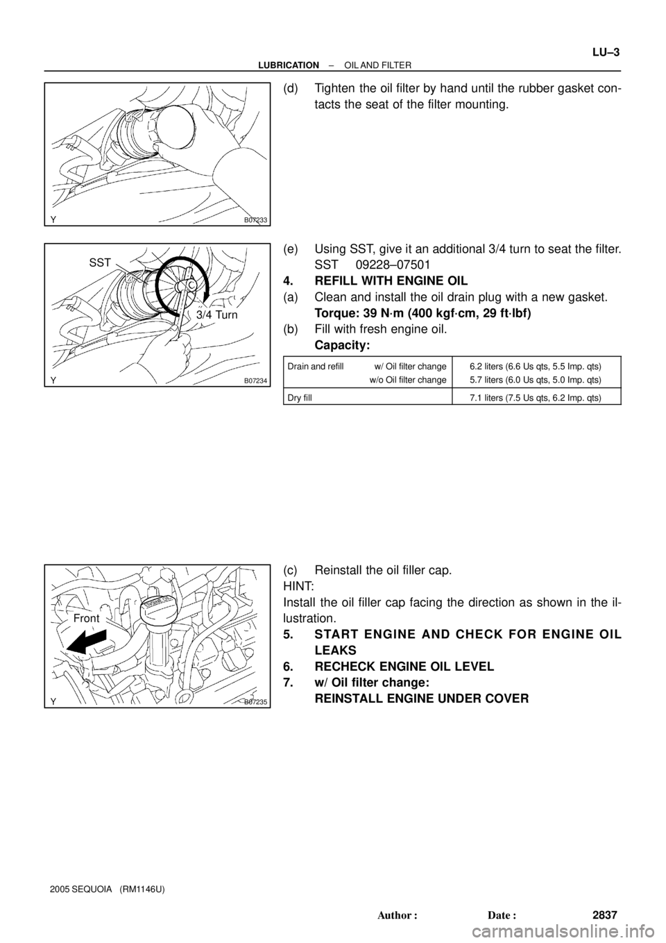
(d) Tighten the oil filter by hand until the rubber gasket con-
tacts the seat of the filter mounting.
(e) Using SST, give it an additional 3/4 turn to seat the filter.
SST 09228±07501
4. REFILL WITH ENGINE OIL
(a) Clean and install the oil drain plug with a new gasket.
Torque: 39 N´m (400 kgf´cm, 29 ft´lbf)
(b) Fill with fresh engine oil.
Capacity:
Drain and refill w/ Oil filter change
w/o Oil filter change6.2 liters (6.6 Us qts, 5.5 Imp. qts)
5.7 liters (6.0 Us qts, 5.0 Imp. qts)
Dry fill7.1 liters (7.5 Us qts, 6.2 Imp. qts)
(c) Reinstall the oil filler cap.
HINT:
Install the oil filler cap facing the direction as shown in the il-
lustration.
5. START ENGINE AND CHECK FOR ENGINE OIL
LEAKS
6. RECHECK ENGINE OIL LEVEL
7. w/ Oil filter change:
REINSTALL ENGINE UNDER COVER