Page 2610 of 4323

INSTALLATION
1. INSTALL CRANKSHAFT TIMING PULLEY
(a) Align the timing pul")
EM1WY±01
A04446
SST
Inward
A04447
A04342
± ENGINE MECHANICALTIMING BELT
EM±23
2602 Author�: Date�:
2005 SEQUOIA (RM1146U)
INSTALLATION
1. INSTALL CRANKSHAFT TIMING PULLEY
(a) Align the timing pulley set key with the key groove of the
pulley.
(b) Using SST and a hammer, tap in the timing pulley, facing
the flange side inward.
SST 09223±46011
2. INSTALL NO.1 IDLER PULLEY AND NO.2 IDLER
PULLEY
(a) Apply adhesive 2 or 3 threads of the pivot bolt.
Adhesive:
Part No. 08833±00080, THREE BOND 1344,
LOCTITE 242 or equivalent
(b) Using a 10 mm hexagon wrench, install the plate washer
and No.1 idler pulley with the pivot bolt.
Torque: 34.5 N´m (350 kgf´cm, 25 ft´lbf)
(c) Install the No.2 idler pulley with the bolt.
Torque: 34.5 N´m (350 kgf´cm, 25 ft´lbf)
(d) Check that the No.1 and No.2 idler pulleys moves
smoothly.
3. TEMPORARILY INSTALL TIMING BELT
NOTICE:
The engine should be cold.
(a) Remove any oil or water on the crankshaft pulley, oil
pump pulley, water pump pulley, No.1 idler pulley and
No.2 idler pulley, and keep them clean.
NOTICE:
Only wipe the pulleys; do not use any cleansing agent.
(b) Align the installation mark on the timing belt with the tim-
ing mark of the crankshaft timing pulley.
(c) Install the timing belt on the crankshaft timing pulley, No.1
idler pulley and No.2 idler pulley.
4. INSTALL TIMING BELT COVER SPACER
(a) Install the gasket to the cover spacer.
(b) Install the cover spacer.
Page 2611 of 4323

5. INSTALL TIMING BELT GUIDE
Install the belt guide with the cup side facing ou")
A04448
A23314
SST
A08660
A23315
SST
EM±24
± ENGINE MECHANICALTIMING BELT
2603 Author�: Date�:
2005 SEQUOIA (RM1146U)
5. INSTALL TIMING BELT GUIDE
Install the belt guide with the cup side facing outward.
6. INSTALL NO.1 TIMING BELT COVER
Install the timing belt cover with the 4 bolts.
7. INSTALL CRANKSHAFT PULLEY
(a) Align the pulley set key with the key groove of the crank-
shaft pulley.
(b) Using SST and a hammer, tap in the crankshaft pulley.
SST 09223±46011
8. INSTALL DRIVE BELT TENSIONER
Install the belt tensioner with the bolt and 2 nuts.
Torque: 26 N´m (265 kgf´cm, 19 ft´lbf)
HINT:
Use a bolt of 106 mm (4.18 in.) in length.
9. INSTALL GENERATOR (See page CH±16)
10. CHECK CRANKSHAFT PULLEY POSITION
Check that the timing mark of the crankshaft pulley is aligned
with timing mark º0º of the No.1 timing belt cover.
11. INSTALL, LH CAMSHAFT TIMING PULLEY
(a) Align the camshaft knock pin with the knock pin groove of
the timing pulley, and slide the timing pulley.
(b) Temporarily install the 4 bolts of the camshaft timing
pulley.
(c) Hold the camshaft timing pulley with SST, and tighten the
pulley bolt.
SST 09960±10010 (09962±01000, 09963±01000)
Torque: 8.1 N´m (83 kgf´cm, 72 in.´lbf)
Page 2761 of 4323

SF1XG±01
B17551
KeywayKey
B17552
ºSº Mark
Triangle Mark
B17553
SST
Rib
ºMAX.º Mark
ºAº Mark
Triangle Mark
B17489Tube Joint Clip
± SFIFUEL PUMP
SF±19
2753 Author�: Date�:
2005 SEQUOIA (RM1146U)
INSTALLATION
1. INSTALL FUEL PUMP ASSEMBLY
(a) Install a new gasket to the fuel tank.
(b) Install the fuel pump assembly to the fuel tank.
NOTICE:
Be careful not to bend the arm of the fuel sender gauge.
(c) Align the keyway of the fuel suction tube support with the
key of the fuel suction plate No.1.
(d) Apply MP grease to the entire interior surface of the fuel
pump gauge retainer.
(e) Align the triangle mark on the new fuel pump gauge re-
tainer with the ºSº mark on the fuel tank while pushing
down the fuel suction tube. Attach the fuel pump gauge
retainer.
(f) Rotate the fuel pump gauge retainer by hand. Use an SST
to tighten the fuel pump gauge retainer by turning it one
and a half times. The triangle mark on the fuel pump
gauge retainer must be positioned between the ºAº and
ºMAX.º marks on the fuel tank.
SST 09808±14020 (09808±01410, 09808±01420,
09808±01430)
NOTICE:
Do not use other tools in this operation. Damage to the fuel
pump gauge retainer and the fuel tank may result.
HINT:
A rib on the fuel pump gauge retainer fits into a tip of the SST.
2. CONNECT FUEL SUCTION TUBE
Connect the fuel pump tube and return tube to the fuel tank with
the tube joint clips.
Page 2938 of 4323
COLUMN SHIFT ASSEMBLY
2930 Author�: Date�:
2005 SEQUOIA (RM1146U)
(g) Install the parking lock cable No. 2 to column upper brack-
et with the cl")
D02002
AT±22
± AUTOMATIC TRANSMISSION (A750E, A750F)COLUMN SHIFT ASSEMBLY
2930 Author�: Date�:
2005 SEQUOIA (RM1146U)
(g) Install the parking lock cable No. 2 to column upper brack-
et with the clip.
(h) Install the cable end to the sliding block of the column up-
per bracket with the screw.
Torque: 2.2 N´m (23 kgf´cm, 19 in.´lbf)
(i) After installation, check the following items.
(1) When the pedal button is pushed, shift lever should
be locked.
(2) When the pedal button is released, shift lever
should be unlocked.
4. INSTALL STEERING COLUMN ASSEMBLY
(See page SR±23)
5. ADJUST CABLE HOUSING
(a) Shift the shift lever to the P position.
(b) Turn the ignition key to the LOCK position.
(c) Loosen the 2 bolts and adjust the cable housing.
HINT:
�Pedal button should touch the pedal plate cushion.
�Brake pedal should not be moved by the pedal button.
�Cable housing should not be toughed the brake pedal
and the brake pedal plate cushion.
(d) Torque the 2 bolts.
Torque: 10.5 N´m (110 kgf´cm, 8 ft´lbf)
6. CONFIRM SHIFT LOCK SYSTEM OPERATION
(a) Only when the brake pedal is engaged and the ignition
key is not in the LOCK position, the shift lever can be
shifted from the P position to other positions.
When the shift lever is in the P position and the brake ped-
al is released, the shift lever cannot be shifted from P posi-
tion to other positions.
(b) When the shift lever is not in the P position, the ignition
key cannot be turned to the LOCK position.
Only when the shift lever is in the P position, the ignition
key can be removed.
(c) Cable No. 1 and No. 2 should not be deformed by other
parts located around the steering column.
Page 2972 of 4323
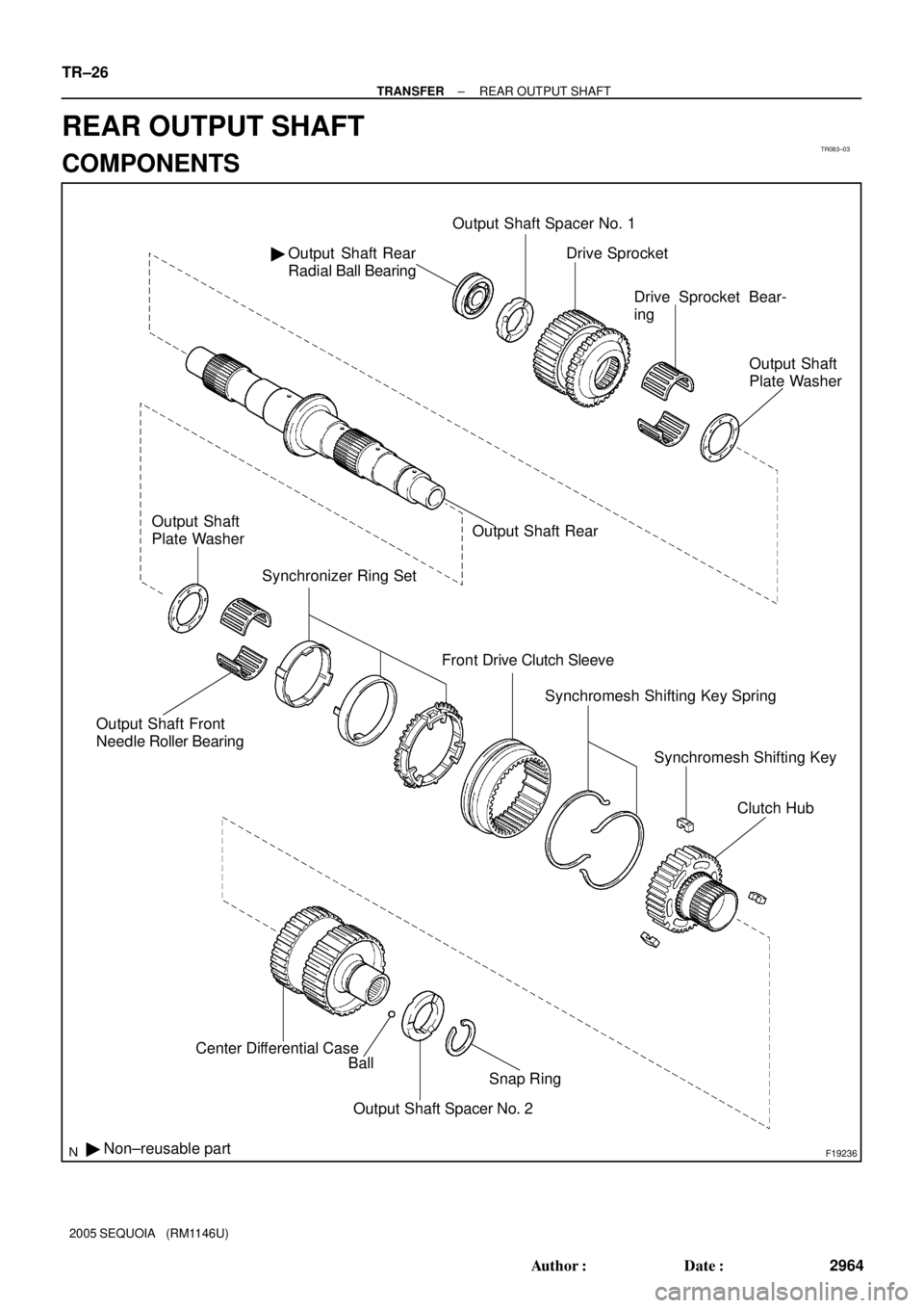
TR083±03
F19236
Output Shaft Rear
Radial Ball Bearing �Output Shaft Spacer No. 1
Output Shaft Front
Needle Roller Bearing
Synchronizer Ring Set
Front Drive Clutch Sleeve
� Non±reusable partCenter Differential Case
Ball
Snap Ring
Output Shaft Spacer No. 2Drive Sprocket
Drive Sprocket Bear-
ing
Output Shaft
Plate Washer
Output Shaft Rear Output Shaft
Plate Washer
Synchromesh Shifting Key Spring
Synchromesh Shifting Key
Clutch Hub
TR±26
± TRANSFERREAR OUTPUT SHAFT
2964 Author�: Date�:
2005 SEQUOIA (RM1146U)
REAR OUTPUT SHAFT
COMPONENTS
Page 2974 of 4323
F19280
F19281
F19282
SST
F19283
TR±28
± TRANSFERREAR OUTPUT SHAFT
2966 Author�: Date�:
2005 SEQUOIA (RM1146U)
5. REMOVE FRONT DRIVE CLUTCH SLEEVE
(a) Using a screwdriver, remove the 2 shifting key springs.
(b) Remove the 3 shifting keys.
(c) Remove the front drive clutch sleeve.
6. REMOVE SYNCHRONIZER RING SET
7. REMOVE DRIVE SPROCKET
(a) Using SST and a press, remove the output shaft rear ra-
dial ball bearing.
SST 09555±55010
(b) Remove the output shaft spacer No. 1 and drive sprocket.
(c) Remove the output shaft plate washer and drive sprocket
bearing.
Page 2977 of 4323
TR0DJ±01
F19283
F19751
SST
Groove
F19281
F19293
F19294
± TRANSFERREAR OUTPUT SHAFT
TR±31
2969 Author�: Date�:
2005 SEQUOIA (RM1146U)
REASSEMBLY
1. INSTALL DRIVE SPROCKET
(a) Install the output shaft plate washer and drive sprocket
bearing to the output shaft rear.
(b) Install the drive sprocket and output shaft spacer No. 1 to
the output shaft rear.
(c) Using SST and a press, install a new output shaft rear ra-
dial ball bearing.
SST 09316±60011 (09316±00011, 09316±00071)
NOTICE:
Install the output shaft rear radial ball bearing so that the
groove for the snap ring does not face the drive sprocket.
2. INSTALL SYNCHRONIZER RING SET
3. INSTALL FRONT DRIVE CLUTCH SLEEVE
4. INSTALL CLUTCH HUB
(a) Install the 3 shifting keys to the clutch hub.
(b) Install the 2 shifting key springs to the clutch hub.
NOTICE:
Position the shifting key springs so that their end gaps are
not aligned.
Page 3200 of 4323

REPLACEMENT
1. REMOVE FRONT WHEEL
2. INSPECT PAD LINING THICKNESS
Check the pad thickness an")
BR10K±04
F07748
F07749
R13537
± BRAKEFRONT BRAKE PAD
BR±25
3192 Author�: Date�:
2005 SEQUOIA (RM1146U)
REPLACEMENT
1. REMOVE FRONT WHEEL
2. INSPECT PAD LINING THICKNESS
Check the pad thickness and replace pads if not within specifi-
cation.
Minimum thickness: 1.0 mm (0.039 in.)
3. REMOVE CLIP, 2 PINS AND ANTI±RATTLE SPRING
4. REMOVE 2 PADS WITH 4 ANTI±SQUEAL SHIMS
NOTICE:
The anti±rattle spring and clip can be used again provided
that they have sufficient rebound, no deformation, cracks
or wear, and have had all rust, dirt and foreign particles
cleaned off.
5. CHECK DISC THICKNESS AND RUNOUT
(See page BR±30)
6. INSTALL NEW PADS
NOTICE:
When replacing worn pads, the anti±squeal shims must be
replaced together with the pads.
(a) Draw out a small amount of brake fluid from the reservoir.
(b) Press in the pistons with a monkey wrench handle or
equivalent.
HINT:
�Tape the monkey wrench handle before use.
�Always change the pad on one wheel at a time as there
is a possibility of the opposite piston flying out.
�If the piston is difficult to push in, loosen the bleeder plug
and push in the piston while letting some brake fluid es-
cape.
(c) Install the 4 anti±squeal shims to new pads.