Page 1797 of 4323
I24831
Transponder Key ECU
Sub J/B No. 3
+B
J43
J/C
51
O
BatteryF10
FL BlockW±R
B
4
IG BEngine Room J/B W±R32
1J
1E Instrument Panel J/B
A
AGND O14
T16 T16 1
2
W±R
3A 3B
81
2C
2D ECU±B
SHORT PIN
± DIAGNOSTICSENGINE IMMOBILISER SYSTEM
DI±1595
1789 Author�: Date�:
2005 SEQUOIA (RM1146U)
Power source circuit
CIRCUIT DESCRIPTION
This circuit provides power to operate the transponder key ECU.
WIRING DIAGRAM
DI7TO±07
Page 1799 of 4323
I24835
Instrument Panel J/B
6 9
BR
1F 1D W±B
A
IEJ8
J/C12
C6C516
LG±B7
T16IND Combination MeterTransponder Key ECU
Security
± DIAGNOSTICSENGINE IMMOBILISER SYSTEM
DI±1597
1791 Author�: Date�:
2005 SEQUOIA (RM1146U)
Security Indicator Light Circuit
CIRCUIT DESCRIPTION
When the transponder key is registered, the transponder key ECU outputs the key registration condition by
illuminating, blinking or turning off the security indicator.
WIRING DIAGRAM
DIABJ±03
Page 1805 of 4323
I28425
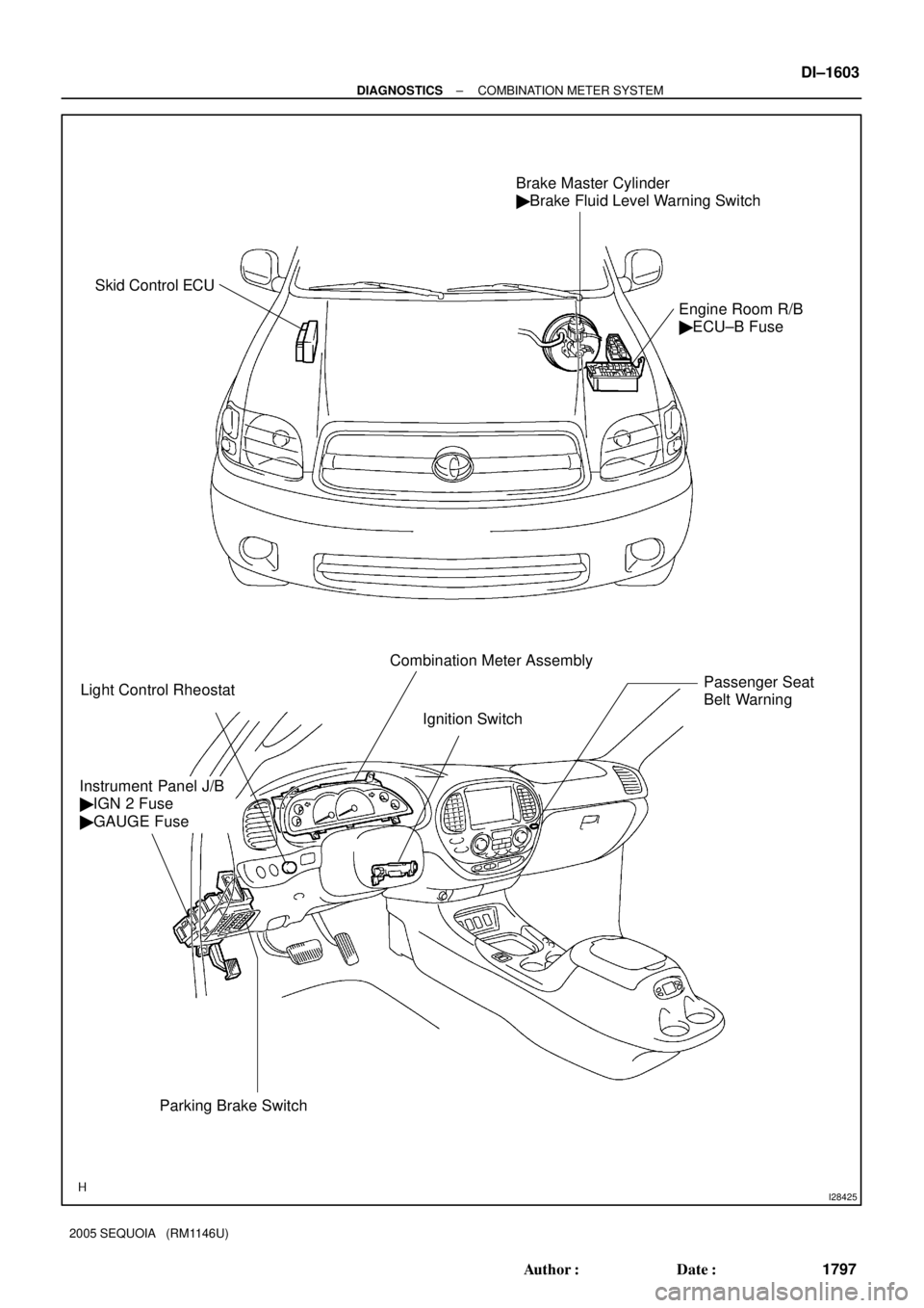
Brake Master Cylinder
� Brake Fluid Level Warning Switch
Engine Room R/B
� ECU±B Fuse
Light Control RheostatCombination Meter Assembly
Instrument Panel J/B
� IGN 2 Fuse
� GAUGE Fuse
Parking Brake SwitchIgnition Switch
Passenger Seat
Belt Warning
Skid Control ECU
± DIAGNOSTICSCOMBINATION METER SYSTEM
DI±1603
1797 Author�: Date�:
2005 SEQUOIA (RM1146U)
Page 1831 of 4323
I28557
I18
Ignition SWInstrument Panel J/BCombination Meter
Engine Room J/B
Sub J/B No. 4
IEBattery J8
J/CIA5 F10
Fusible
Link BlockC6
C5 C6
C6
C5 1F
1J
1C1D
1H
1C
1C1D
1D
1J
1J
2C 2D
222C
4B 4A AM2IG2
ST2
(*1) (*2)
W±B
W±R
B±R
B±WBR
B±O W±R
B±R
W±R W±RB±R
B±R B
AB
B
BB 893
98
2
1 1
1 4
5Short Pin
ECU±B
AM2
STA 4 5
8 211 9
37 6
53 396
IGN1
IGN212
23
24
28
Engine Room R/B
*1: Head (USA)
*2: Tail (CANADA)
± DIAGNOSTICSCOMBINATION METER SYSTEM
DI±1629
1823 Author�: Date�:
2005 SEQUOIA (RM1146U)
WIRING DIAGRAM
Page 1832 of 4323
DI±1630
± DIAGNOSTICSCOMBINATION METER SYSTEM
1824 Author�: Date�:
2005 SEQUOIA (RM1146U)
INSPECTION PROCEDURE
1 Check fuse.
CHECK:
Measure the resistance of the IGN2 fuse and IGN1 fuse in the instrument panel J/B.
OK:
Below 1 W
CHECK:
Measure the resistance of the STA fuse in the engine room R/B.
OK:
Below 1 W
CHECK:
Measure the resistance of the ECU±B fuse and AM2 fuse in the engine room R/B.
OK:
Below 1 W
NG Inspect for short circuit in harness and all com-
ponents connected to fuse.
OK
Page 1834 of 4323
I28558
C612
W±B
Battery AW
58BR
IECombination Meter
W±L I18
Ignition SW
2 1
AM1 IG1
B±Y
W Instrument Panel J/B
AM1
21 47
6 1 6
9 1C
1C
1D 1E
1L
1FR±L
R±LSub J/B No. 3
3B 3A515C524
C610 R±L
Y±RY
Y±RY
13
23 19
26
IG4
IG4
IG4
GAUGE
B V1
Vehicle Speed Sensor
(Combination Meter)
F10
Fusible Link Block
J8
J/C DI±1632
± DIAGNOSTICSCOMBINATION METER SYSTEM
1826 Author�: Date�:
2005 SEQUOIA (RM1146U)
Malfunction in speedometer
CIRCUIT DESCRIPTION
The speedometer detects vehicle speed based on a 4±pulse signal from the vehicle speed sensor.
WIRING DIAGRAM
DID8Z±01
Page 1848 of 4323
I28561
R6
Rheostat
To Each
Illumination Parts
To Each
Illumination Parts
Instrument Panel J/B
Combination Meter
I18
Ignition SW J8
J/C
Sub J/B No. 3
F10
Fusible Link Block
Engine Room J/B
Battery
IET
ILL±
E
TR
IG C5
C612 22
24
C6
Illumination 1F
1J 1C1D 1H
1C
1C8
2
11 9
34 13
6
IGN1
AM11H 1E
1C4
1 1F
1L 6
7 56
12
2DECU±IG
2188
3A 3E
8
4
51 3 4
5 6
ALT
AM2 IG2
AM2 11
2C A
A
AM1 IG1
G
W±G
W±B
BR W±G
W±G
W±BW±G
B±R
B±YB±O
B±R
W
W±L
W±RB±R
BW±RB DI±1646
± DIAGNOSTICSCOMBINATION METER SYSTEM
1840 Author�: Date�:
2005 SEQUOIA (RM1146U)
WIRING DIAGRAM
Page 1852 of 4323
I28562
Combination Meter
Instrument Panel J/B
Engine Room J/B I18
Ignition SW Front Seat
Inner Belt
(Buckle
SW LH)
*1: w/ Power Seat
*2: w/o Power Seat Battery
BH IEJ8
J/C
F10
FLB BI2J24
J/C
4
5
BB B
B
AC5
C6
12 24
C64
Seat
BeltBuzzer
2D2C 11
AM2 1F 1C
1D1H
1C
1J 211
9 3
7
6 IGN1
56
AM2 IG2
W±BB±O
BR
W±R W±B
(*1)(*2)
W±B
(*1) W±B
(*1)(*1) (*2) (*1)(*1) (*1) G±Y G±YG±Y
(*2)
1 33 213
B16 B16 B16 B16
W±RG±Y
B±R W±RBI2 IN1
313
W±B
(*2)
DI±1650
± DIAGNOSTICSCOMBINATION METER SYSTEM
1844 Author�: Date�:
2005 SEQUOIA (RM1146U)
Seat belt warning for driver's seat does not operate
CIRCUIT DESCRIPTION
A buzzer and indicator are included in the seat belt warning system. When the ignition switch is ON and the
seat belt on the driver side is not fastened, both the buzzer and indicator operate.
The buzzer and indicator are built into the combination meter.
WIRING DIAGRAM
DID94±01


*1: w/ Power Seat
*2: w/o Power Seat Battery
BH IEJ8
J/C
F10
FLB BI2J24
J/C
4
5
BB")