Page 1724 of 4323
I28700
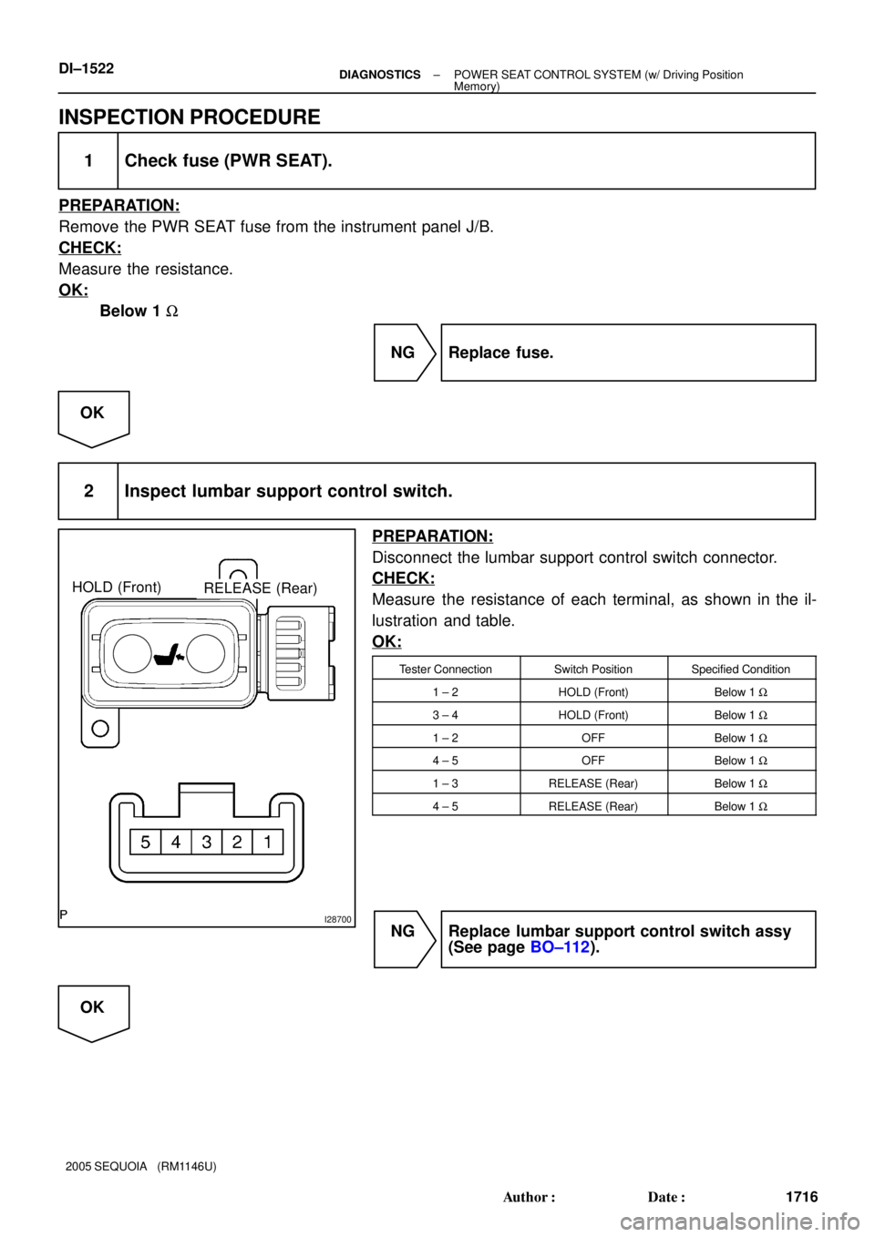
HOLD (Front)RELEASE (Rear)
DI±1522± DIAGNOSTICSPOWER SEAT CONTROL SYSTEM (w/ Driving Position
Memory)
1716 Author�: Date�:
2005 SEQUOIA (RM1146U)
INSPECTION PROCEDURE
1 Check fuse (PWR SEAT).
PREPARATION:
Remove the PWR SEAT fuse from the instrument panel J/B.
CHECK:
Measure the resistance.
OK:
Below 1 W
NG Replace fuse.
OK
2 Inspect lumbar support control switch.
PREPARATION:
Disconnect the lumbar support control switch connector.
CHECK:
Measure the resistance of each terminal, as shown in the il-
lustration and table.
OK:
Tester ConnectionSwitch PositionSpecified Condition
1 ± 2HOLD (Front)Below 1 W
3 ± 4HOLD (Front)Below 1 W
1 ± 2OFFBelow 1 W
4 ± 5OFFBelow 1 W
1 ± 3RELEASE (Rear)Below 1 W
4 ± 5RELEASE (Rear)Below 1 W
NG Replace lumbar support control switch assy
(See page BO±112).
OK
Page 1730 of 4323
I28451
BatteryJ/C
I18
Ignition SW
1
2
AM1IG1
5W BF10
FL Block
ALT
81L 1CInstrument Panel J/B
7 J52 J51
21AM1
6
1C4
1 78 L±Y1
MPX1 M6 WW
C5 C53430 Combination MeterPosition Control
ECU & Switch
P
L±Y
L±R
L±R CCPL RB 62 P1
Park/Neutral
Position Switch
B±Y
W±LGAUGEIPOIG49 BEAN
1D DI±1528
± DIAGNOSTICSPOWER SEAT CONTROL SYSTEM (w/ Driving Position
Memory)
1722 Author�: Date�:
2005 SEQUOIA (RM1146U)
Park/neutral position switch circuit
CIRCUIT DESCRIPTION
The power seat memory system operates only when the ignition switch is in the ON position and the park/
neutral position is in the P (park) position.
The position control ECU & switch assy detects the P position, via multiplex communication, through the
park/neutral position switch.
WIRING DIAGRAM
DIDEC±01
Page 1752 of 4323
DI3CG±10
I28396
DLC3
Instrument Panel J/B
Ignition SwitchECM Cruise Control Switch
Stop Light Switch
� STOP Fuse
� IGN1 Fuse
� AM1 Fuse
� GAUGE FuseCombination Meter
� CRUISE Main Indicator Light
Spiral Cable Sub±assy
DI±1550
± DIAGNOSTICSCRUISE CONTROL SYSTEM
1744 Author�: Date�:
2005 SEQUOIA (RM1146U)
PARTS LOCATION
Page 1754 of 4323

I24840
Battery 117
1E
AM2
1 2W±RI18
Ignition SW
B±R
IG2
85E4ECM
ST1± 1
STOP16
5 S14
Stop Light SW
7G±Y
3
6E4STP
1C B±O
3
F10 FL Block
ALT IGN1
B B
W
1F 1L1
2D 2C15
W±RAM2
ST2
1C2
1J 2
4A2 B±OW4
2G±Y
Instrument Panel J/B
Sub J/B No. 4
Engine Room J/B
Instrument Panel J/B4L±B Sub J/B No. 4
4D1
1
4A4E DI±1552
± DIAGNOSTICSCRUISE CONTROL SYSTEM
1746 Author�: Date�:
2005 SEQUOIA (RM1146U)
DTC P0571/52 Stop light switch circuit malfunction
CIRCUIT DESCRIPTION
When the brake pedal is depressed, the stop light switch assy sends a signal to the ECM. When the ECM
receives this signal, it cancels the cruise control.
Fail±safe function operates to enable normal driving even if there is a malfunction in the stop light signal
circuit.
The cancel condition occurs when positive battery voltage is applied to terminal STP.
When the brake is applied, battery positive voltage is normally applied to terminal STP of the ECM through
the STOP fuse and the stop light switch assy, and the ECM turns the cruise control off.
DTC No.DTC Detection ConditionTrouble Area
P0571/52Stop light switch does not turn off even once the vehicle is
driven�Stop light switch assy
�Stop light switch assy circuit
�ECM
WIRING DIAGRAM
DIAB6±05
Page 1759 of 4323
I28462
Combination Meter
Instrument Panel J/B
I18
Ignition SWEngine Room J/BPIECM
B±O LG±R
Cruise
W±R
Battery
IG2 B±R24
32
1H 1C
AM2
62
1 IGN1
1C6
7C5 E518
1C 1J
2C2D
W±R
5
AM2B 11
B54F10
FLB
± DIAGNOSTICSCRUISE CONTROL SYSTEM
DI±1557
1751 Author�: Date�:
2005 SEQUOIA (RM1146U)
CRUISE main indicator light circuit
CIRCUIT DESCRIPTION
The CRUISE main indicator light comes on while the cruise control system is in operation and blinks when
there are any problems with the system.
DTCs can be read by counting the number of times the CRUISE main indicator light blinks.
WIRING DIAGRAM
DIDF3±01
Page 1769 of 4323
I28464
ECM
Sub J/B No.4
23
E4
1328
T5
15
A205
4E
TC
TC5
4B
5
4C 5
4D
5
4A 15
1F 9
1A
J43
J/C12
T17 P±B P±B Translate ECU
TCP±B
P±B
O
O 4 TC
CG D6
DLC3 Airbag Sensor
Assembly
Instrument Panel J/BTire Pressure
ECU
P±B
G
A A
IGTC
± DIAGNOSTICSCRUISE CONTROL SYSTEM
DI±1567
1761 Author�: Date�:
2005 SEQUOIA (RM1146U)
Diagnosis circuit
CIRCUIT DESCRIPTION
Making a short circuit between terminals TC and CG of the DLC3 will output DTCs from the DLC3.
WIRING DIAGRAM
HINT:
When a particular warning light stays blinking, a ground short in the wiring of terminal TC of the DLC3 or an
internal ground short in the relevant ECU is suspected.
DIDF5±01
Page 1781 of 4323
DI3DP±10
I28395
ECM Transponder Key Coil
Transponder Key Amplifier Instrument
Panel J/B
� IGN Fuse
Engine Room J/B
� ECU±B Fuse
� EFI No. 1 Fuse
Transponder Key ECU
Combination Meter
� Security Indicator Light
� MIL
DLC3
(Located behind the combination meter)
± DIAGNOSTICSENGINE IMMOBILISER SYSTEM
DI±1579
1773 Author�: Date�:
2005 SEQUOIA (RM1146U)
PARTS LOCATION
Page 1789 of 4323
I24834
F10
FL Block1J 1CInstrument Panel J/B
IG2B±R I18
Ignition SW
Battery 56
B B W±R AM22
17
IGN1
1C1E
7
3
4 5Transponder Key ECU
IG 2
2CT16
2DB±O
1B±O
W±R
1 AM2 Engine Room J/BSub J/B No. 4
212
4D 4A
± DIAGNOSTICSENGINE IMMOBILISER SYSTEM
DI±1587
1781 Author�: Date�:
2005 SEQUOIA (RM1146U)
Code 13 is not output
CIRCUIT DESCRIPTION
The transponder key ECU outputs DTC 13 when the ignition switch is ON.
HINT:
DTC 13 is a normal code.
DTC No.DTC Detecting ConditionTrouble Area
13Ignition switch operates normally.
�Ignition switch
�Transponder key ECU
�Wire harness
WIRING DIAGRAM
DIABF±04