Page 1860 of 4323
I28564
I18
Ignition SWInstrument Panel J/BCombination Meter
Engine Room J/B F10
Fusible LB
BatteryIGN1
AM2
AM2 IG2
2D 2C11 1C 1H
1C1J 2
11
37 56B±R B±O
W±R
BB
4 5C624
W±R DI±1658
± DIAGNOSTICSCOMBINATION METER SYSTEM
1852 Author�: Date�:
2005 SEQUOIA (RM1146U)
Malfunction in volt meter
CIRCUIT DESCRIPTION
The voltmeter indicates the voltage applied to the IG terminal of the combination meter.
WIRING DIAGRAM
DID96±01
Page 1861 of 4323

± DIAGNOSTICSCOMBINATION METER SYSTEM
DI±1659
1853 Author�: Date�:
2005 SEQUOIA (RM1146U)
INSPECTION PROCEDURE
HINT:
Start the inspection from step 1 when using the hand±held tester and start from step 2 when not using the
hand±held tester.
1 Perform active test by hand±held tester.
PREPARATION:
(a) Connect the hand±held tester to the DLC3.
(b) Turn the ignition switch ON, and push the hand±held tester main switch ON.
CHECK:
From the display on the tester, perform the ºACTIVE TESTº.
METER:
ItemTest DetailsDiagnostic Note
VOLT METER9 V / 12 V / 15 V / 18VConfirm that the vehicle is stopped and engine is
idling.
OK:
Volt meter readings change according to hand±held tester operation.
NG Replace combination meter
(See page IN±35).
OK
2 Check fuse.
CHECK:
Measure the resistance of the IGN1 fuse in the instrument panel J/B.
OK:
Below 1 W
CHECK:
Measure the resistance of the AM2 fuse in the engine room J/B.
OK:
Below 1 W
NG Inspect for short circuit in harness and all com-
ponents connected to fuse.
OK
Page 1869 of 4323
DI274±08
I28411
Ignition Switch Instrument Panel J/B
� ECU±IG Fuse
� SUN ROOF Fuse
Sliding Roof Gear Assembly
� Sliding Roof ECU
� Sliding Roof Motor
Sliding Roof Control Switch
± DIAGNOSTICSSLIDING ROOF SYSTEM
DI±1667
1861 Author�: Date�:
2005 SEQUOIA (RM1146U)
PARTS LOCATION
Page 1870 of 4323
DI277±14
I18700
J8
J/CB±R
2
L±WIG Instrument Panel J/B I18
Ignition SW
1IG1
AM1 B±Y4
1C
6
1CAM1
1 2ECU±IG
SUN ROOF1
1M
5
1M
1
1L8
5
B
W±L
B58 ALT F10
Fusible Link Block
W
Instrument Panel J/B
W±BW±B 7
1M 10
1F
IE Battery7
AS19
Sliding Roof
Control ECU
E DI±1668
± DIAGNOSTICSSLIDING ROOF SYSTEM
1862 Author�: Date�:
2005 SEQUOIA (RM1146U)
CIRCUIT INSPECTION
Power Source Circuit
CIRCUIT DESCRIPTION
This circuit provides power to operate the sliding roof control ECU.
WIRING DIAGRAM
Page 1873 of 4323
I18701
4
3
10
9 W±BS19
Sliding Roof
Control ECU
UP
DWN
CLS
OPN J8
J/CO59
O5 10
O512
O511 UP
DWN
CLS
OPN E O51
W±B1M7
1F10
IEAInstrument Panel J/BOverhead Module
R±Y
R±W
G±Y
P±B
± DIAGNOSTICSSLIDING ROOF SYSTEM
DI±1671
1865 Author�: Date�:
2005 SEQUOIA (RM1146U)
Sliding Roof Control Switch Circuit
CIRCUIT DESCRIPTION
The sliding roof control switch is built into the overhead module.
WIRING DIAGRAM
DI94F±05
Page 1900 of 4323

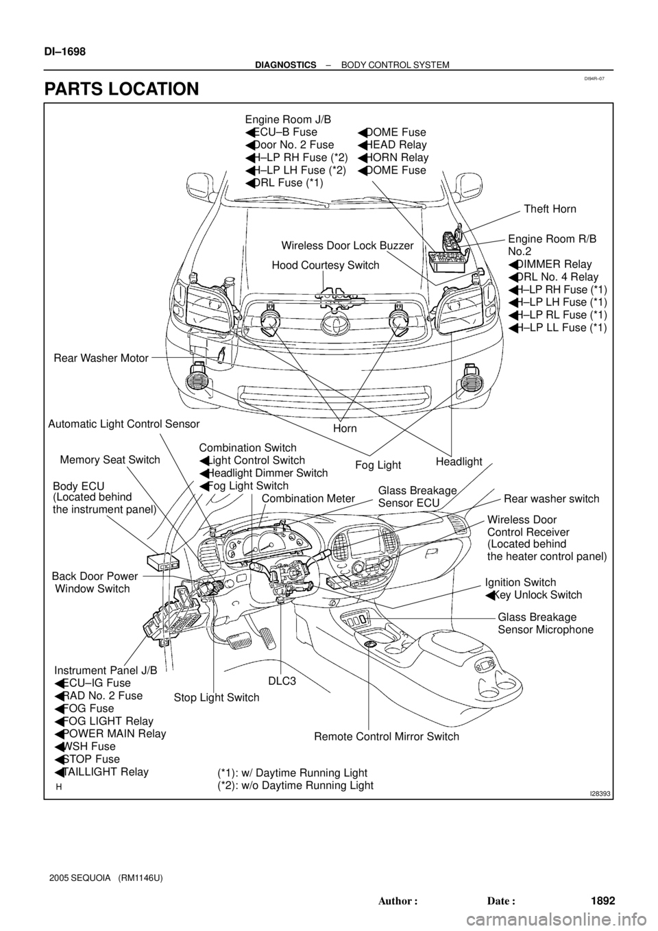
DI94R±07
I28393
Hood Courtesy Switch Engine Room J/B
� ECU±B Fuse
� Door No. 2 Fuse
� H±LP RH Fuse (*2)
� H±LP LH Fuse (*2)
� DRL Fuse (*1)
Rear Washer Motor
Horn
Headlight
Rear washer switch
Ignition Switch
� Key Unlock Switch
DLC3 Body ECU
Instrument Panel J/B
� ECU±IG Fuse
� RAD No. 2 Fuse
� FOG Fuse
� FOG LIGHT Relay
� POWER MAIN Relay
� WSH Fuse
� STOP Fuse
� TAILLIGHT Relay Back Door Power
Window SwitchTheft Horn
Engine Room R/B
No.2
� DIMMER Relay
� DRL No. 4 Relay
� H±LP RH Fuse (*1)
� H±LP LH Fuse (*1)
� H±LP RL Fuse (*1)
� H±LP LL Fuse (*1)
Fog Light
Wireless Door
Control Receiver Wireless Door Lock Buzzer
Combination Meter Memory Seat Switch
(*1): w/ Daytime Running Light
(*2): w/o Daytime Running Light (Located behind
the instrument panel)
(Located behind
the heater control panel)
� DOME Fuse
� HEAD Relay
� HORN Relay
� DOME Fuse
Automatic Light Control Sensor
Stop Light Switch
Remote Control Mirror SwitchGlass Breakage
Sensor Microphone Glass Breakage
Sensor ECU
Combination Switch
� Light Control Switch
� Headlight Dimmer Switch
� Fog Light Switch DI±1698
± DIAGNOSTICSBODY CONTROL SYSTEM
1892 Author�: Date�:
2005 SEQUOIA (RM1146U)
PARTS LOCATION
Page 1903 of 4323
I28515
Engine Room J/B
Body ECU
Instrument Panel J/B SECURITY
I18
Ignition SWBDR
ACC
BECU S+B B6 L±W
IA5 2D
2C2H
1C 1E
1G
1L
1G
1G1C 1C 1J12
3
45
6 7
10
11
5
6 2
58 1101332
1
6L±W
IA510
B6
B7
B6 1
2 1
8
12DOOR No. 2
ECU±BShort
Pin
2W±L
W±L
W±R
B B
WGR
W±R
P RAD No. 2
AM1
WSH
ECU±IG12AM1
ACC
B7 IG1 W±L
ALT R/B
F10
FL Block
BatteryL±YB±RB±Y
B
W±BB7
B6
IE 12
IG
WIG
GND1 1W±R 12
3A 3ESub J/B No. 3
4Engine Room R/B No. 2
± DIAGNOSTICSBODY CONTROL SYSTEM
DI±1701
1895 Author�: Date�:
2005 SEQUOIA (RM1146U)
WIRING DIAGRAM
Page 1908 of 4323

I24351
Body ECU
11 3
21 5
B 5W
1G TAILLIGHT Relay
To Taillight
F10
Fusible Link BlockLG
B7
ALTTRLY 2 1L
81
BatteryInstrument Panel J/B
LG
DDJ/9
J/C DI±1706
± DIAGNOSTICSBODY CONTROL SYSTEM
1900 Author�: Date�:
2005 SEQUOIA (RM1146U)
Taillight Relay Circuit
CIRCUIT DESCRIPTION
TAILLIGHT relay will be ºONº by operating the light control switch. The transistor which activates the tail light
relay has two sorts: one is activated by the light control switch for fail safe and the other is activated by CPU.
When the theft deterrent system is activated, it causes the transistor in the ECU to switch ON and OFF at
approximately 0.4 sec. intervals. This switches the TAILLIGHT relay ON and OFF, and thus flashing the tail-
lights (See the wiring diagram below).
In this condition, if any of the following operations is done, the transistor in the ECU goes OFF and the TAIL-
LIGHT relay switches OFF, and thus stopping the taillights flashing:
(1) Unlock the front LH or RH door with a key.
(2) Turn the ignition switch to ACC or ON position.
(3) Unlock the doors with the wireless door lock control system.
(4) Wait for approximately 60 seconds.
WIRING DIAGRAM
DI6QY±15