Page 1070 of 1943
H15711
Airbag
Sensor
Assembly2
37
10
121
45
6
8
16
9
14
15
Side Airbag
Assembly (RH) (Squib)
Seat Belt
Pretensioner (RH) Side Airbag Sensor
Assembly (RH)
Front Airbag Sensor (RH)
Front Passenger Airbag
Assembly (Squib)
Spiral Cable
Steering Wheel
Pad (Squib)
Front Airbag Sensor (LH)
Side Airbag Sensor
Assembly (LH) Seat Belt
Pretensioner (LH)
Side Airbag
Assembly (LH) (Squib) 13
11
DI±506
± DIAGNOSTICSSUPPLEMENTAL RESTRAINT SYSTEM
2001 PRIUS (RM778U)
Page 1072 of 1943

DI6OZ±06
DI±508
± DIAGNOSTICSSUPPLEMENTAL RESTRAINT SYSTEM
2001 PRIUS (RM778U)
DIAGNOSTIC TROUBLE CODE CHART
If a malfunction code is displayed during the DTC check, check the circuit listed for that code in the table
below (Proceed to the page given for that circuit.).
DTC No.
(See Page)Detection ItemTrouble AreaSRS
Warning Light
B0100/13
(DI±510)
�Short in D squib circuit�Steering wheel pad (squib)
�Spiral cable
�Airbag sensor assembly
�Wire harness
ON
B0101/14
(DI±515)
�Open in D squib circuit�Steering wheel pad (squib)
�Spiral cable
�Airbag sensor assembly
�Wire harness
ON
B0102/11
(DI±519)
�Short in D squib circuit (to ground)�Steering wheel pad (squib)
�Spiral cable
�Airbag sensor assembly
�Wire harness
ON
B0103/12
(DI±523)
�Short in D squib circuit (to B+)�Steering wheel pad (squib)
�Spiral cable
�Airbag sensor assembly
�Wire harness
ON
B0105/53
(DI±527)�Short in P squib circuit�Front passenger airbag assembly (squib)
�Airbag sensor assembly
�Wire harness
ON
B0106/54
(DI±531)�Open in P squib circuit�Front passenger airbag assembly (squib)
�Airbag sensor assembly
�Wire harness
ON
B0107/51
(DI±534)�Short in P squib circuit (to ground)�Front passenger airbag assembly (squib)
�Airbag sensor assembly
�Wire harness
ON
B0108/52
(DI±537)�Short in P squib circuit (to B+)�Front passenger airbag assembly (squib)
�Airbag sensor assembly
�Wire harness
ON
B0110/43
(DI±540)�Short in side squib (RH) circuit�Side airbag assembly RH (squib)
�Airbag sensor assembly
�Wire harness
Blink
B0111/44
(DI±544)�Open in side squib (RH) circuit�Side airbag assembly RH (squib)
�Airbag sensor assembly
�Wire harness
Blink
B0112/41
(DI±550)�Short in side squib (RH) circuit
(to ground)�Side airbag assembly RH (squib)
�Airbag sensor assembly
�Wire harness
Blink
B0113/42
(DI±550)�Short in side squib (RH) circuit
(to B+)�Side airbag assembly RH (squib)
�Airbag sensor assembly
�Wire harness
Blink
B0115/47
(DI±553)�Short in side squib (LH) circuit�Side airbag assembly LH (squib)
�Airbag sensor assembly
�Wire harness
Blink
B0116/48
(DI±557)�Open in side squib (LH) circuit�Side airbag assembly LH (squib)
�Airbag sensor assembly
�Wire harness
Blink
Page 1077 of 1943
DI6P3±06
H01451
Y±B
D+ A1814Airbag Sensor Assembly
13
A18
D± Y 1
2
Spiral
Cable D Squib
± DIAGNOSTICSSUPPLEMENTAL RESTRAINT SYSTEM
DI±515
2001 PRIUS (RM778U)
CIRCUIT INSPECTION
DTC B0100/13 Short in D Squib Circuit
CIRCUIT DESCRIPTION
The D squib circuit consists of the airbag sensor assembly, spiral cable and steering wheel pad.
It causes the airbag to deploy when the airbag deployment conditions are satisfied.
For details of the function of each component, see OPERATION on page RS±2.
DTC B0100/13 is recorded when a short is detected in the D squib circuit.
DTC No.DTC Detecting ConditionTrouble Area
B0100/13
�Short circuit between D+ wire harness and D± wire har-
ness of squib
�D squib malfunction
�Spiral cable malfunction
�Airbag sensor assembly malfunction�Steering wheel pad (D squib)
�Spiral cable
�Airbag sensor assembly
�Wire harness
WIRING DIAGRAM
Page 1078 of 1943
H01001H02142H02193
D SquibSpiral
Cable
Airbag
Sensor
Assembly
D+
(±)(+) D±
DI±516
± DIAGNOSTICSSUPPLEMENTAL RESTRAINT SYSTEM
2001 PRIUS (RM778U)
INSPECTION PROCEDURE
1 Prepare for inspection (See step 1 on page DI±629).
2 Check D squib circuit.
PREPARATION:
Release the airbag activation prevention mechanism of the
connector (on the airbag sensor assembly side) between the
airbag sensor assembly and the spiral cable (See page
DI±497).
CHECK:
For the connector (on the spiral cable side) between the spiral
cable and the steering wheel pad, measure the resistance be-
tween D+ and D±.
OK:
Resistance: 1 MW or Higher
NG Go to step 5.
OK
Page 1080 of 1943

AB0119FI1390
H01003
H10600H10599
D SquibSpiral
CableAirbag
Sensor
Assembly
ON
DTC B0100/13
DLC3
" u
Tc CG
DI±518
± DIAGNOSTICSSUPPLEMENTAL RESTRAINT SYSTEM
2001 PRIUS (RM778U)
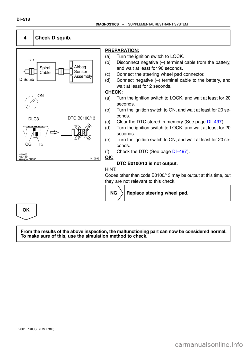
4 Check D squib.
PREPARATION:
(a) Turn the ignition switch to LOCK.
(b) Disconnect negative (±) terminal cable from the battery,
and wait at least for 90 seconds.
(c) Connect the steering wheel pad connector.
(d) Connect negative (±) terminal cable to the battery, and
wait at least for 2 seconds.
CHECK:
(a) Turn the ignition switch to LOCK, and wait at least for 20
seconds.
(b) Turn the ignition switch to ON, and wait at least for 20 se-
conds.
(c) Clear the DTC stored in memory (See page DI±497).
(d) Turn the ignition switch to LOCK, and wait at least for 20
seconds.
(e) Turn the ignition switch to ON, and wait at least for 20 se-
conds.
(f) Check the DTC (See page DI±497).
OK:
DTC B0100/13 is not output.
HINT:
Codes other than code B0100/13 may be output at this time, but
they are not relevant to this check.
NG Replace steering wheel pad.
OK
From the results of the above inspection, the malfunctioning part can now be considered normal.
To make sure of this, use the simulation method to check.
Page 1081 of 1943

H01000H02142H02195
D SquibSpiral
Cable
Airbag
Sensor
Assembly
D+ u"
(±) (+) D±
R14286H01004H01138
D SquibSpiral
Cable
Airbag
Sensor
Assembly
D+
(±)(+)D±
± DIAGNOSTICSSUPPLEMENTAL RESTRAINT SYSTEM
DI±519
2001 PRIUS (RM778U)
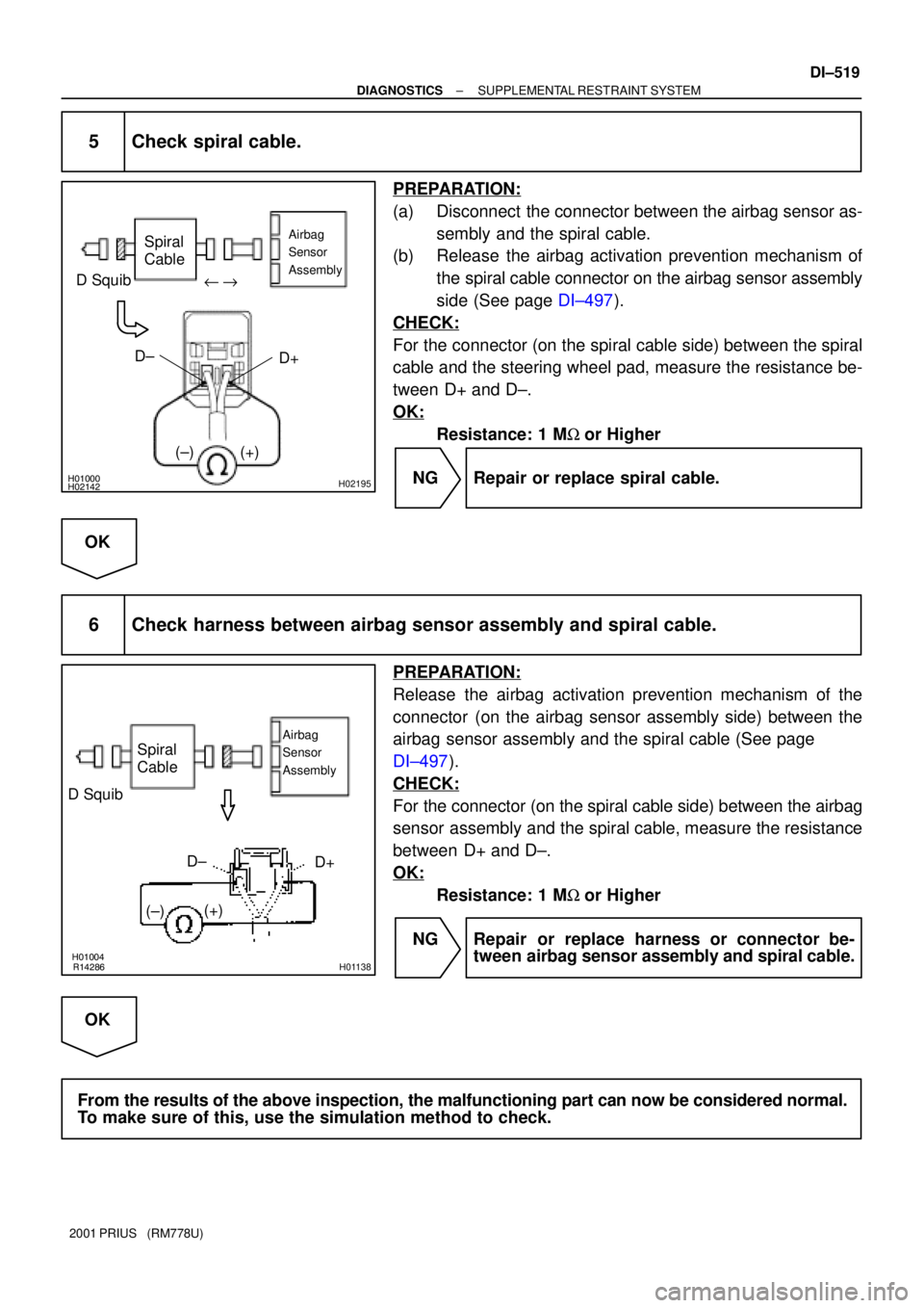
5 Check spiral cable.
PREPARATION:
(a) Disconnect the connector between the airbag sensor as-
sembly and the spiral cable.
(b) Release the airbag activation prevention mechanism of
the spiral cable connector on the airbag sensor assembly
side (See page DI±497).
CHECK:
For the connector (on the spiral cable side) between the spiral
cable and the steering wheel pad, measure the resistance be-
tween D+ and D±.
OK:
Resistance: 1 MW or Higher
NG Repair or replace spiral cable.
OK
6 Check harness between airbag sensor assembly and spiral cable.
PREPARATION:
Release the airbag activation prevention mechanism of the
connector (on the airbag sensor assembly side) between the
airbag sensor assembly and the spiral cable (See page
DI±497).
CHECK:
For the connector (on the spiral cable side) between the airbag
sensor assembly and the spiral cable, measure the resistance
between D+ and D±.
OK:
Resistance: 1 MW or Higher
NG Repair or replace harness or connector be-
tween airbag sensor assembly and spiral cable.
OK
From the results of the above inspection, the malfunctioning part can now be considered normal.
To make sure of this, use the simulation method to check.
Page 1082 of 1943

H01001H02142H02196
D SquibSpiral
Cable
Airbag
Sensor
Assembly
D+
(±) (+) D±
u"
DI±520
± DIAGNOSTICSSUPPLEMENTAL RESTRAINT SYSTEM
2001 PRIUS (RM778U)
DTC B0101/14 Open in D Squib Circuit
CIRCUIT DESCRIPTION
The D squib circuit consists of the airbag sensor assembly, spiral cable and steering wheel pad.
It causes the airbag to deploy when the airbag deployment conditions are satisfied.
For details of the function of each component, see OPERATION on page RS±2.
DTC B0101/14 is recorded when an open is detected in the D squib circuit.
DTC No.DTC Detecting ConditionTrouble Area
B0101/14
�Open circuit in D+ wire harness or D± wire harness of
squib
�D squib malfunction
�Spiral cable malfunction
�Airbag sensor assembly malfunction�Steering wheel pad (D squib)
�Spiral cable
�Airbag sensor assembly
�Wire harness
WIRING DIAGRAM
See page DI±510.
INSPECTION PROCEDURE
1 Prepare for inspection (See step 1 on page DI±629).
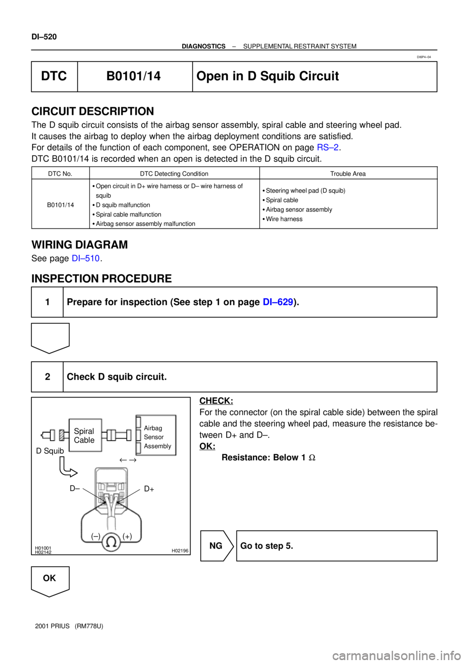
2 Check D squib circuit.
CHECK:
For the connector (on the spiral cable side) between the spiral
cable and the steering wheel pad, measure the resistance be-
tween D+ and D±.
OK:
Resistance: Below 1 W
NG Go to step 5.
OK
DI6P4±04
Page 1083 of 1943

H01002H02144AB0119W02044 H10600H10602
D SquibSpiral
CableAirbag
Sensor
Assembly
ON
DTC B0101/14
DLC3"u
D+D±
Tc CG
± DIAGNOSTICSSUPPLEMENTAL RESTRAINT SYSTEM
DI±521
2001 PRIUS (RM778U)
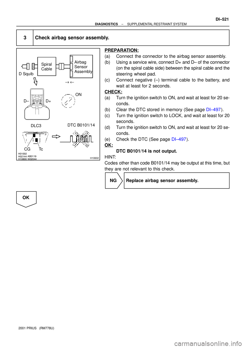
3 Check airbag sensor assembly.
PREPARATION:
(a) Connect the connector to the airbag sensor assembly.
(b) Using a service wire, connect D+ and D± of the connector
(on the spiral cable side) between the spiral cable and the
steering wheel pad.
(c) Connect negative (±) terminal cable to the battery, and
wait at least for 2 seconds.
CHECK:
(a) Turn the ignition switch to ON, and wait at least for 20 se-
conds.
(b) Clear the DTC stored in memory (See page DI±497).
(c) Turn the ignition switch to LOCK, and wait at least for 20
seconds.
(d) Turn the ignition switch to ON, and wait at least for 20 se-
conds.
(e) Check the DTC (See page DI±497).
OK:
DTC B0101/14 is not output.
HINT:
Codes other than code B0101/14 may be output at this time, but
they are not relevant to this check.
NG Replace airbag sensor assembly.
OK