Page 1093 of 1943
H01000AB0119H02146H02202
D SquibSpiral
Cable
Airbag
Sensor
Assembly
D+ u"
(±) (+)ON
H01004R14288
AB0119
H08261
D SquibSpiral
Cable
(±)(+)D+
Airbag
Sensor
Assembly
ON
± DIAGNOSTICSSUPPLEMENTAL RESTRAINT SYSTEM
DI±531
2001 PRIUS (RM778U)
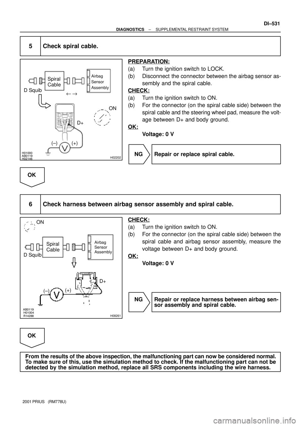
5 Check spiral cable.
PREPARATION:
(a) Turn the ignition switch to LOCK.
(b) Disconnect the connector between the airbag sensor as-
sembly and the spiral cable.
CHECK:
(a) Turn the ignition switch to ON.
(b) For the connector (on the spiral cable side) between the
spiral cable and the steering wheel pad, measure the volt-
age between D+ and body ground.
OK:
Voltage: 0 V
NG Repair or replace spiral cable.
OK
6 Check harness between airbag sensor assembly and spiral cable.
CHECK:
(a) Turn the ignition switch to ON.
(b) For the connector (on the spiral cable side) between the
spiral cable and airbag sensor assembly, measure the
voltage between D+ and body ground.
OK:
Voltage: 0 V
NG Repair or replace harness between airbag sen-
sor assembly and spiral cable.
OK
From the results of the above inspection, the malfunctioning part can now be considered normal.
To make sure of this, use the simulation method to check. If the malfunctioning part can not be
detected by the simulation method, replace all SRS components including the wire harness.
Page 1197 of 1943
H01026H06508H06509
LOCKAirbag
Sensor
Assembly
P/T Squib (LH)
Side Airbag
Sensor (LH)
Side Squib
(LH)P Squib
D Squib
Spiral
Cable
Front Airbag
Sensor (RH) Front Airbag
Sensor (LH)
P/T Squib (RH)
Side Airbag
Sensor (RH)
Side Squib
(RH)
± DIAGNOSTICSSUPPLEMENTAL RESTRAINT SYSTEM
DI±635
2001 PRIUS (RM778U)
INSPECTION PROCEDURE
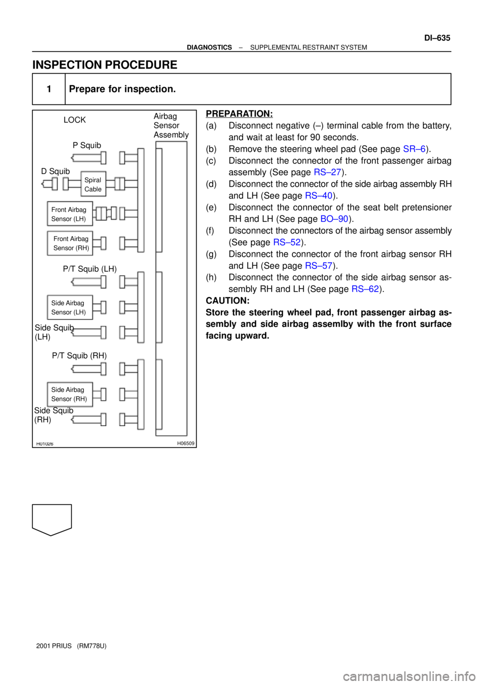
1 Prepare for inspection.
PREPARATION:
(a) Disconnect negative (±) terminal cable from the battery,
and wait at least for 90 seconds.
(b) Remove the steering wheel pad (See page SR±6).
(c) Disconnect the connector of the front passenger airbag
assembly (See page RS±27).
(d) Disconnect the connector of the side airbag assembly RH
and LH (See page RS±40).
(e) Disconnect the connector of the seat belt pretensioner
RH and LH (See page BO±90).
(f) Disconnect the connectors of the airbag sensor assembly
(See page RS±52).
(g) Disconnect the connector of the front airbag sensor RH
and LH (See page RS±57).
(h) Disconnect the connector of the side airbag sensor as-
sembly RH and LH (See page RS±62).
CAUTION:
Store the steering wheel pad, front passenger airbag as-
sembly and side airbag assemlby with the front surface
facing upward.
Page 1198 of 1943
AB0119H01298H01299
Airbag Sensor Assembly
ON
IG1
ACC
(+) (±)
H01249
ON
DI±636
± DIAGNOSTICSSUPPLEMENTAL RESTRAINT SYSTEM
2001 PRIUS (RM778U)
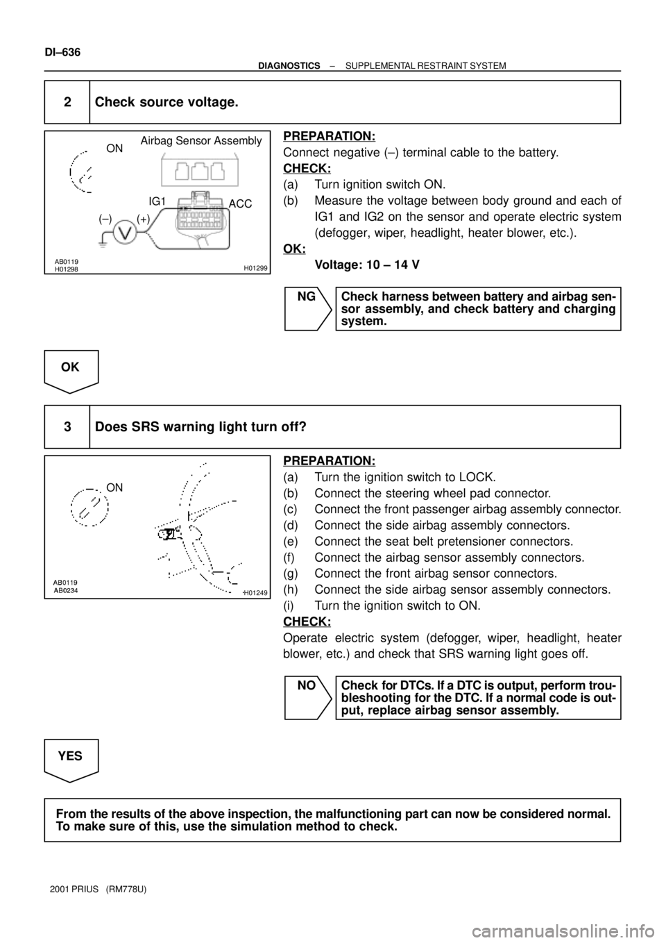
2 Check source voltage.
PREPARATION:
Connect negative (±) terminal cable to the battery.
CHECK:
(a) Turn ignition switch ON.
(b) Measure the voltage between body ground and each of
IG1 and IG2 on the sensor and operate electric system
(defogger, wiper, headlight, heater blower, etc.).
OK:
Voltage: 10 ± 14 V
NG Check harness between battery and airbag sen-
sor assembly, and check battery and charging
system.
OK
3 Does SRS warning light turn off?
PREPARATION:
(a) Turn the ignition switch to LOCK.
(b) Connect the steering wheel pad connector.
(c) Connect the front passenger airbag assembly connector.
(d) Connect the side airbag assembly connectors.
(e) Connect the seat belt pretensioner connectors.
(f) Connect the airbag sensor assembly connectors.
(g) Connect the front airbag sensor connectors.
(h) Connect the side airbag sensor assembly connectors.
(i) Turn the ignition switch to ON.
CHECK:
Operate electric system (defogger, wiper, headlight, heater
blower, etc.) and check that SRS warning light goes off.
NO Check for DTCs. If a DTC is output, perform trou-
bleshooting for the DTC. If a normal code is out-
put, replace airbag sensor assembly.
YES
From the results of the above inspection, the malfunctioning part can now be considered normal.
To make sure of this, use the simulation method to check.
Page 1655 of 1943
± SUSPENSION AND AXLETIRE AND WHEEL
SA±3
1453 Author�: Date�:
2001 PRIUS (RM778U)
5. CHECK FRONT SUSPENSION FOR LOOSENESS
6. CHECK STEERING LINKAGE FOR LOOSENESS
7. CHECK BALL JOINT FOR LOOSENESS
8. CHECK SHOCK ABSORBER WORKS PROPERLY
�Check if oil leaks
�Check mounting bushings for wear
�Bounce front and rear of the vehicle
Page 1656 of 1943
F11573
Front:
Rear:SA1CK±11
Z03382
Alignment
TesterGauge
F07339
SA±4
± SUSPENSION AND AXLEFRONT WHEEL ALIGNMENT
1454 Author�: Date�:
2001 PRIUS (RM778U)
FRONT WHEEL ALIGNMENT
INSPECTION
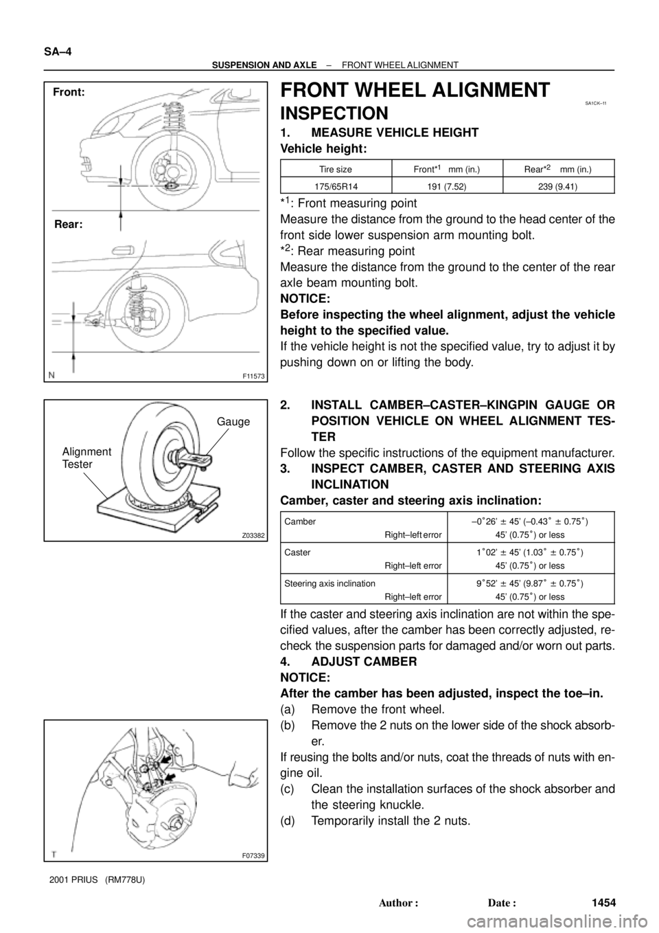
1. MEASURE VEHICLE HEIGHT
Vehicle height:
Tire sizeFront*1 mm (in.)Rear*2 mm (in.)
175/65R14191 (7.52)239 (9.41)
*1: Front measuring point
Measure the distance from the ground to the head center of the
front side lower suspension arm mounting bolt.
*
2: Rear measuring point
Measure the distance from the ground to the center of the rear
axle beam mounting bolt.
NOTICE:
Before inspecting the wheel alignment, adjust the vehicle
height to the specified value.
If the vehicle height is not the specified value, try to adjust it by
pushing down on or lifting the body.
2. INSTALL CAMBER±CASTER±KINGPIN GAUGE OR
POSITION VEHICLE ON WHEEL ALIGNMENT TES-
TER
Follow the specific instructions of the equipment manufacturer.
3. INSPECT CAMBER, CASTER AND STEERING AXIS
INCLINATION
Camber, caster and steering axis inclination:
Camber
Right±left error±0°26' ± 45' (±0.43° ± 0.75°)
45' (0.75°) or less
Caster
Right±left error1°02' ± 45' (1.03° ± 0.75°)
45' (0.75°) or less
Steering axis inclination
Right±left error9°52' ± 45' (9.87° ± 0.75°)
45' (0.75°) or less
If the caster and steering axis inclination are not within the spe-
cified values, after the camber has been correctly adjusted, re-
check the suspension parts for damaged and/or worn out parts.
4. ADJUST CAMBER
NOTICE:
After the camber has been adjusted, inspect the toe±in.
(a) Remove the front wheel.
(b) Remove the 2 nuts on the lower side of the shock absorb-
er.
If reusing the bolts and/or nuts, coat the threads of nuts with en-
gine oil.
(c) Clean the installation surfaces of the shock absorber and
the steering knuckle.
(d) Temporarily install the 2 nuts.
Page 1658 of 1943
SA3213
Front A
DB
C
F11574
F11575
SA0028
Front AB
A B
A: Inside
B: Outside SA±6
± SUSPENSION AND AXLEFRONT WHEEL ALIGNMENT
1456 Author�: Date�:
2001 PRIUS (RM778U)
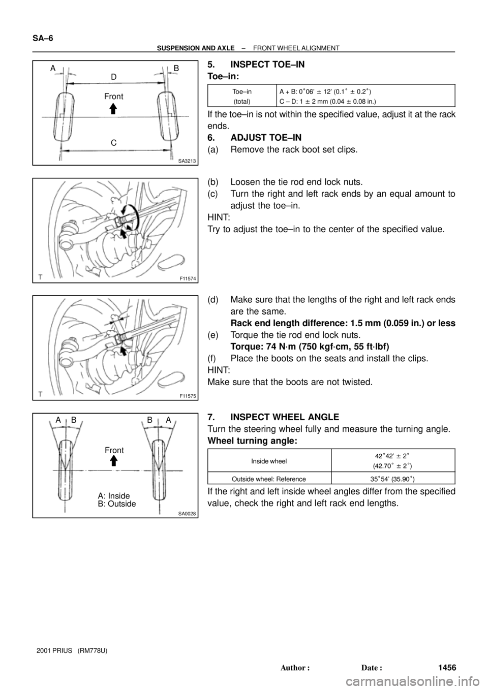
5. INSPECT TOE±IN
Toe±in:
Toe±in
(total)A + B: 0°06' ± 12' (0.1° ± 0.2°)
C ± D: 1 ± 2 mm (0.04 ± 0.08 in.)
If the toe±in is not within the specified value, adjust it at the rack
ends.
6. ADJUST TOE±IN
(a) Remove the rack boot set clips.
(b) Loosen the tie rod end lock nuts.
(c) Turn the right and left rack ends by an equal amount to
adjust the toe±in.
HINT:
Try to adjust the toe±in to the center of the specified value.
(d) Make sure that the lengths of the right and left rack ends
are the same.
Rack end length difference: 1.5 mm (0.059 in.) or less
(e) Torque the tie rod end lock nuts.
Torque: 74 N´m (750 kgf´cm, 55 ft´lbf)
(f) Place the boots on the seats and install the clips.
HINT:
Make sure that the boots are not twisted.
7. INSPECT WHEEL ANGLE
Turn the steering wheel fully and measure the turning angle.
Wheel turning angle:
Inside wheel42°42' ± 2°
(42.70° ± 2°)
Outside wheel: Reference35°54' (35.90°)
If the right and left inside wheel angles differ from the specified
value, check the right and left rack end lengths.
Page 1663 of 1943
SA20B±01
FA1535
SST
F12940SST
F11576
SST
± SUSPENSION AND AXLEFRONT DRIVE SHAFT
SA±17
2001 PRIUS (RM778U)
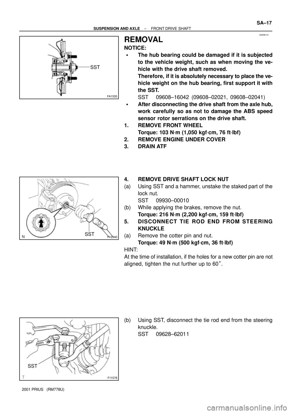
REMOVAL
NOTICE:
�The hub bearing could be damaged if it is subjected
to the vehicle weight, such as when moving the ve-
hicle with the drive shaft removed.
Therefore, if it is absolutely necessary to place the ve-
hicle weight on the hub bearing, first support it with
the SST.
SST 09608±16042 (09608±02021, 09608±02041)
�After disconnecting the drive shaft from the axle hub,
work carefully so as not to damage the ABS speed
sensor rotor serrations on the drive shaft.
1. REMOVE FRONT WHEEL
Torque: 103 N´m (1,050 kgf´cm, 76 ft´lbf)
2. REMOVE ENGINE UNDER COVER
3. DRAIN ATF
4. REMOVE DRIVE SHAFT LOCK NUT
(a) Using SST and a hammer, unstake the staked part of the
lock nut.
SST 09930±00010
(b) While applying the brakes, remove the nut.
Torque: 216 N´m (2,200 kgf´cm, 159 ft´lbf)
5. DISCONNECT TIE ROD END FROM STEERING
KNUCKLE
(a) Remove the cotter pin and nut.
Torque: 49 N´m (500 kgf´cm, 36 ft´lbf)
HINT:
At the time of installation, if the holes for a new cotter pin are not
aligned, tighten the nut further up to 60°.
(b) Using SST, disconnect the tie rod end from the steering
knuckle.
SST 09628±62011
Page 1671 of 1943
SA1ZW±01
F11576
SST
F11616
F11617
F11586
± SUSPENSION AND AXLEFRONT LOWER SUSPENSION ARM
SA±33
2001 PRIUS (RM778U)
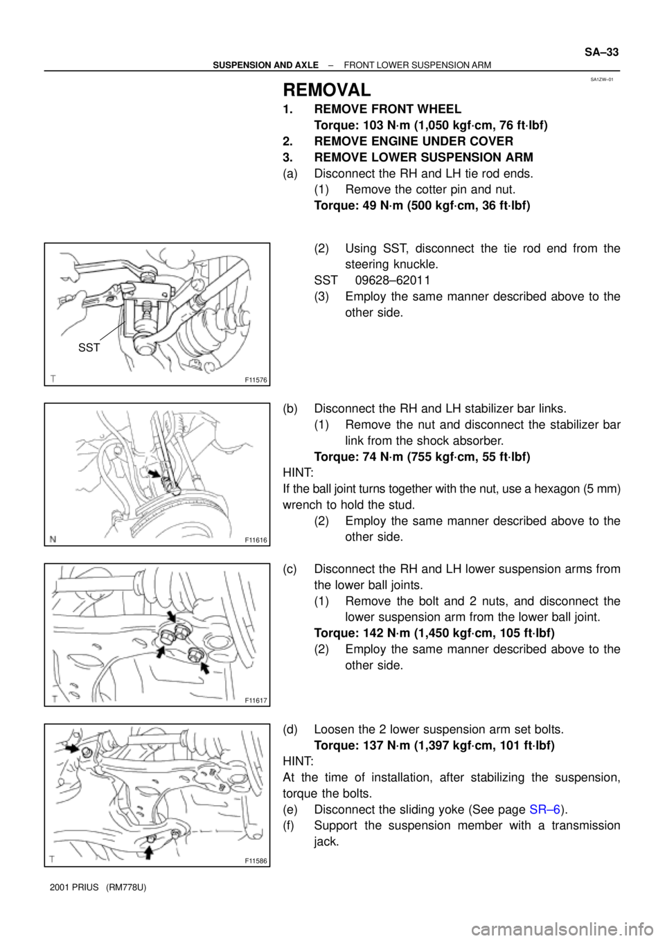
REMOVAL
1. REMOVE FRONT WHEEL
Torque: 103 N´m (1,050 kgf´cm, 76 ft´lbf)
2. REMOVE ENGINE UNDER COVER
3. REMOVE LOWER SUSPENSION ARM
(a) Disconnect the RH and LH tie rod ends.
(1) Remove the cotter pin and nut.
Torque: 49 N´m (500 kgf´cm, 36 ft´lbf)
(2) Using SST, disconnect the tie rod end from the
steering knuckle.
SST 09628±62011
(3) Employ the same manner described above to the
other side.
(b) Disconnect the RH and LH stabilizer bar links.
(1) Remove the nut and disconnect the stabilizer bar
link from the shock absorber.
Torque: 74 N´m (755 kgf´cm, 55 ft´lbf)
HINT:
If the ball joint turns together with the nut, use a hexagon (5 mm)
wrench to hold the stud.
(2) Employ the same manner described above to the
other side.
(c) Disconnect the RH and LH lower suspension arms from
the lower ball joints.
(1) Remove the bolt and 2 nuts, and disconnect the
lower suspension arm from the lower ball joint.
Torque: 142 N´m (1,450 kgf´cm, 105 ft´lbf)
(2) Employ the same manner described above to the
other side.
(d) Loosen the 2 lower suspension arm set bolts.
Torque: 137 N´m (1,397 kgf´cm, 101 ft´lbf)
HINT:
At the time of installation, after stabilizing the suspension,
torque the bolts.
(e) Disconnect the sliding yoke (See page SR±6).
(f) Support the suspension member with a transmission
jack.