Page 1682 of 1943
BR1JA±01
F12629
Front Door Scuff Plate Cowl Side TrimHood Lock Release
Lever Lower Column CoverRadio Tuner Opening CoverCluster Finish Panel
Assembly Hazard Warning Switch
Lower Center Cluster
Finish PanelGlove Compartment
Door Finish PanelInstrument PanelNo. 3 Register No. 2 Side Defroster
Nozzle
Front Pillar GarnishPassenger Air Bag
Assembly Cluster Finish Panel
Combination Meter
Lower Finish PanelSteering Wheel Pad Steering Wheel
Spiral CableUpper Column Cover
Front Door Scuff PlateCowl Side Trim No. 1 RegisterNo. 1 Side Defroster
NozzleFront Pillar Garnish
: Specified torqueN´m (kgf´cm, ft´lbf)
50 (510, 37)
BR±10
± BRAKEPARKING BRAKE PEDAL
2001 PRIUS (RM778U)
COMPONENTS
Page 1698 of 1943
SR1BE±01
F12219
Shift Lever Assembly
Upper Column Cover
Lower Ciolumn CoverSteering Wheel Pad
Steering Wheel
Combination Switch
(w/ Spiral Cable)
Transmission Control
Cable Steering Column
Assembly
Shift Lock Computer
Sub±assembly Sliding Yoke
No. 2 Intermediate
Shaft Assembly
Column Hole Cover
Main Shaft Lower
Dust Seal
Hood Lock
Release LeverLower Instrument
Finish Panel
N´m (kgf´cm, ft´lbf): Specified torque
35 (360, 26)
25 (260, 19)
49 (50, 43 in.´lbf)
35 (360, 26)
35 (360, 26)
25 (260, 19)
50 (510, 37)
8.8 (90, 78 in.´lbf)
Torx Screw
8.0 (80, 69 in.´lbf)
8.8 (90, 78 in.´lbf)
Torx Screw
4.0 (40, 35 in.´lbf)
Instrument Finish
Panel
49 (50, 43 in.´lbf)
SR±4
± STEERINGTILT STEERING COLUMN
1577 Author�: Date�:
2001 PRIUS (RM778U)
TILT STEERING COLUMN
COMPONENTS
Page 1700 of 1943
SR1BF±01
F12211
Torx
ScrewTorx Screw
Case
F12212
Correct WrongAirbag Connector
F12213SST
Matchmarks
SR±6
± STEERINGTILT STEERING COLUMN
2001 PRIUS (RM778U)
REMOVAL
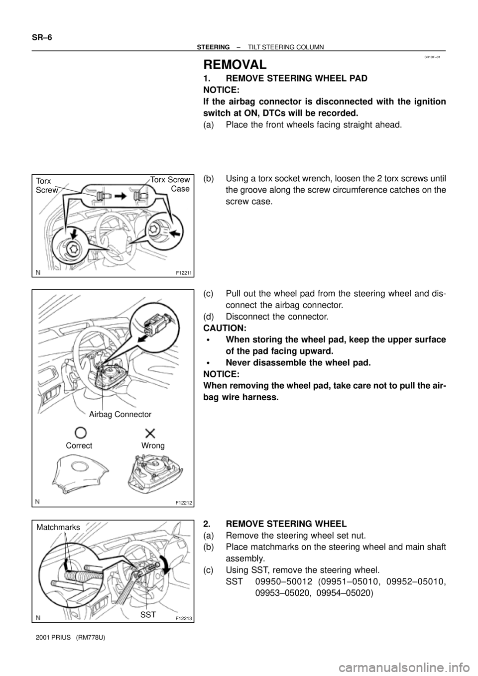
1. REMOVE STEERING WHEEL PAD
NOTICE:
If the airbag connector is disconnected with the ignition
switch at ON, DTCs will be recorded.
(a) Place the front wheels facing straight ahead.
(b) Using a torx socket wrench, loosen the 2 torx screws until
the groove along the screw circumference catches on the
screw case.
(c) Pull out the wheel pad from the steering wheel and dis-
connect the airbag connector.
(d) Disconnect the connector.
CAUTION:
�When storing the wheel pad, keep the upper surface
of the pad facing upward.
�Never disassemble the wheel pad.
NOTICE:
When removing the wheel pad, take care not to pull the air-
bag wire harness.
2. REMOVE STEERING WHEEL
(a) Remove the steering wheel set nut.
(b) Place matchmarks on the steering wheel and main shaft
assembly.
(c) Using SST, remove the steering wheel.
SST 09950±50012 (09951±05010, 09952±05010,
09953±05020, 09954±05020)
Page 1708 of 1943
F12830
F08459
Marks
± STEERINGTILT STEERING COLUMN
SR±15
2001 PRIUS (RM778U)
11. CONNECT TRANSMISSION CONTROL CABLE
12. INSTALL SPIRAL CABLE (See page BE±19)
13. INSTALL COMBINATION SWITCH WITH SPIRAL
CABLE
(a) Install the combination switch with spiral cable with the 3
screws.
(b) Connect the airbag connector.
(c) Connect the connectors.
14. INSTALL UPPER AND LOWER COLUMN COVERS
(a) Install the upper column cover with the screw.
(b) Install the lower column cover with the 3 screws.
15. INSTALL LOWER INSTRUMENT FINISH PANEL
(a) Connect the connectors and DLC3 and install the lower
instrument finish panel.
(b) Install the screw and bolt.
(c) Connect the hood lock release lever with the 2 screws.
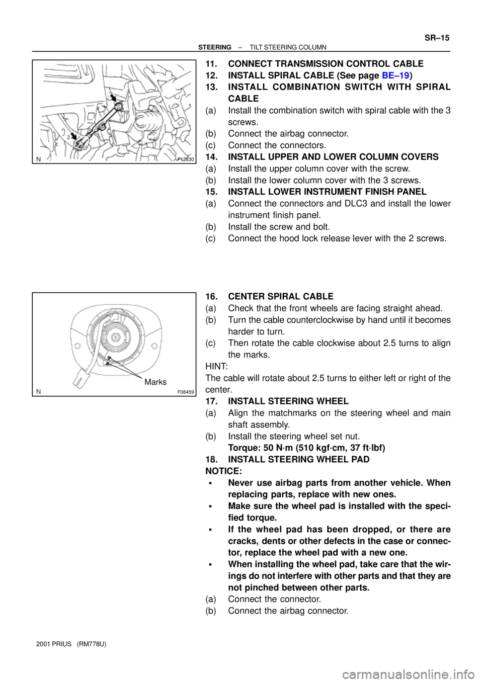
16. CENTER SPIRAL CABLE
(a) Check that the front wheels are facing straight ahead.
(b) Turn the cable counterclockwise by hand until it becomes
harder to turn.
(c) Then rotate the cable clockwise about 2.5 turns to align
the marks.
HINT:
The cable will rotate about 2.5 turns to either left or right of the
center.
17. INSTALL STEERING WHEEL
(a) Align the matchmarks on the steering wheel and main
shaft assembly.
(b) Install the steering wheel set nut.
Torque: 50 N´m (510 kgf´cm, 37 ft´lbf)
18. INSTALL STEERING WHEEL PAD
NOTICE:
�Never use airbag parts from another vehicle. When
replacing parts, replace with new ones.
�Make sure the wheel pad is installed with the speci-
fied torque.
�If the wheel pad has been dropped, or there are
cracks, dents or other defects in the case or connec-
tor, replace the wheel pad with a new one.
�When installing the wheel pad, take care that the wir-
ings do not interfere with other parts and that they are
not pinched between other parts.
(a) Connect the connector.
(b) Connect the airbag connector.
Page 1709 of 1943
F12217
Torx ScrewTorx Screw
Case
SR±16
± STEERINGTILT STEERING COLUMN
2001 PRIUS (RM778U)
(c) Install the steering wheel pad after confirming that the cir-
cumference groove of the torx screws is caught on the
screw case.
(d) Using a torx socket wrench, torque the 2 screws.
Torque: 8.8 N´m (90 kgf´cm, 78 in.´lbf)
19. CHECK STEERING WHEEL CENTER POINT
20. PERFORM CALIBRATION OF TORQUE SENSOR
ZERO POINT (See page DI±454)
Page 1712 of 1943
SR1BL±01
F12196
F12214
A
B
± STEERINGELECTRIC POWER STEERING GEAR
SR±19
2001 PRIUS (RM778U)
REMOVAL
NOTICE:
Remove the steering wheel assembly before the steering
gear removal, because there is possibility of breaking of
the spiral cable.
1. PLACE FRONT WHEELS FACING STRAIGHT AHEAD
2. REMOVE STEERING WHEEL PAD (See page SR±6)
3. REMOVE STEERING WHEEL (See page SR±6)
4. REMOVE RH AND LH ENGINE UNDER COVERS
5. DISCONNECT RH AND LH TIE ROD ENDS (See page
SA±9)
6. DISCONNECT STABILIZER BAR (See page SA±41)
7. DISCONNECT LOWER SUSPENSION ARM FROM
LOWER BALL JOINT (See page SA±41)
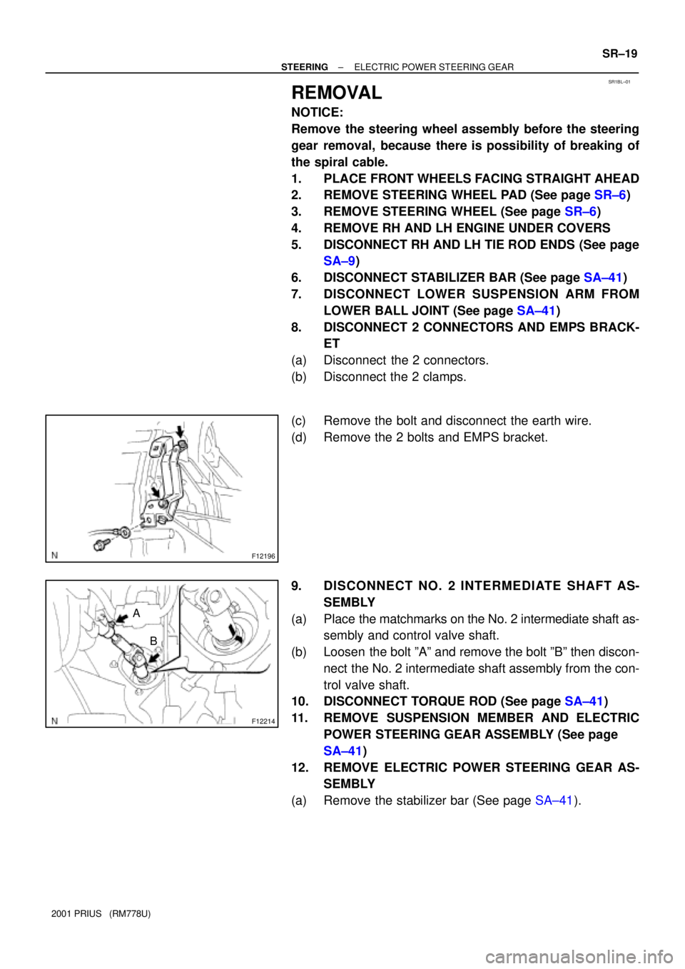
8. DISCONNECT 2 CONNECTORS AND EMPS BRACK-
ET
(a) Disconnect the 2 connectors.
(b) Disconnect the 2 clamps.
(c) Remove the bolt and disconnect the earth wire.
(d) Remove the 2 bolts and EMPS bracket.
9. DISCONNECT NO. 2 INTERMEDIATE SHAFT AS-
SEMBLY
(a) Place the matchmarks on the No. 2 intermediate shaft as-
sembly and control valve shaft.
(b) Loosen the bolt ºAº and remove the bolt ºBº then discon-
nect the No. 2 intermediate shaft assembly from the con-
trol valve shaft.
10. DISCONNECT TORQUE ROD (See page SA±41)
11. REMOVE SUSPENSION MEMBER AND ELECTRIC
POWER STEERING GEAR ASSEMBLY (See page
SA±41)
12. REMOVE ELECTRIC POWER STEERING GEAR AS-
SEMBLY
(a) Remove the stabilizer bar (See page SA±41).
Page 1716 of 1943
SR1BN±01
F12267
F12268
Fulcrum LengthSST
F12269
± STEERINGELECTRIC POWER STEERING GEAR
SR±23
2001 PRIUS (RM778U)
REASSEMBLY
NOTICE:
When using a vise, do not overtighten it.
1. INSTALL EARTH WIRE
Install the earth wire with the bolt.
Torque: 5.5 N´m (60 kgf´cm, 52 in.´lbf)
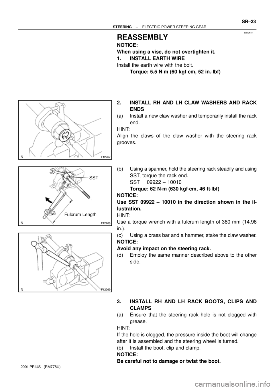
2. INSTALL RH AND LH CLAW WASHERS AND RACK
ENDS
(a) Install a new claw washer and temporarily install the rack
end.
HINT:
Align the claws of the claw washer with the steering rack
grooves.
(b) Using a spanner, hold the steering rack steadily and using
SST, torque the rack end.
SST 09922 ± 10010
Torque: 62 N´m (630 kgf´cm, 46 ft´lbf)
NOTICE:
Use SST 09922 ± 10010 in the direction shown in the il-
lustration.
HINT:
Use a torque wrench with a fulcrum length of 380 mm (14.96
in.).
(c) Using a brass bar and a hammer, stake the claw washer.
NOTICE:
Avoid any impact on the steering rack.
(d) Employ the same manner described above to the other
side.
3. INSTALL RH AND LH RACK BOOTS, CLIPS AND
CLAMPS
(a) Ensure that the steering rack hole is not clogged with
grease.
HINT:
If the hole is clogged, the pressure inside the boot will change
after it is assembled and the steering wheel is turned.
(b) Install the boot, clip and clamp.
NOTICE:
Be careful not to damage or twist the boot.
Page 1719 of 1943
F12196
F12214
Matchmarks
A
B
SR±26
± STEERINGELECTRIC POWER STEERING GEAR
2001 PRIUS (RM778U)
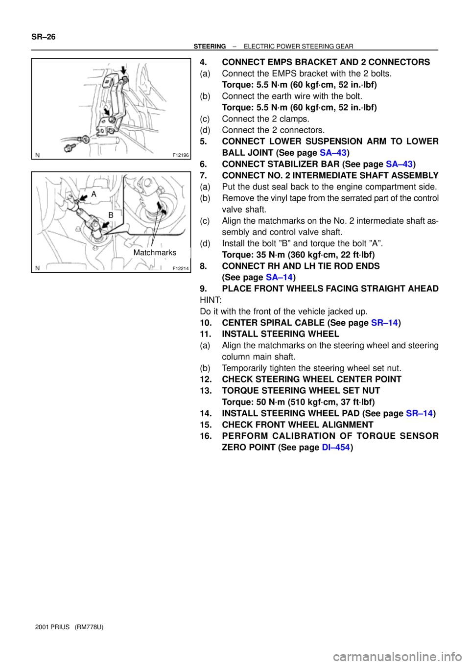
4. CONNECT EMPS BRACKET AND 2 CONNECTORS
(a) Connect the EMPS bracket with the 2 bolts.
Torque: 5.5 N´m (60 kgf´cm, 52 in.´lbf)
(b) Connect the earth wire with the bolt.
Torque: 5.5 N´m (60 kgf´cm, 52 in.´lbf)
(c) Connect the 2 clamps.
(d) Connect the 2 connectors.
5. CONNECT LOWER SUSPENSION ARM TO LOWER
BALL JOINT (See page SA±43)
6. CONNECT STABILIZER BAR (See page SA±43)
7. CONNECT NO. 2 INTERMEDIATE SHAFT ASSEMBLY
(a) Put the dust seal back to the engine compartment side.
(b) Remove the vinyl tape from the serrated part of the control
valve shaft.
(c) Align the matchmarks on the No. 2 intermediate shaft as-
sembly and control valve shaft.
(d) Install the bolt ºBº and torque the bolt ºAº.
Torque: 35 N´m (360 kgf´cm, 22 ft´lbf)
8. CONNECT RH AND LH TIE ROD ENDS
(See page SA±14)
9. PLACE FRONT WHEELS FACING STRAIGHT AHEAD
HINT:
Do it with the front of the vehicle jacked up.
10. CENTER SPIRAL CABLE (See page SR±14)
11. INSTALL STEERING WHEEL
(a) Align the matchmarks on the steering wheel and steering
column main shaft.
(b) Temporarily tighten the steering wheel set nut.
12. CHECK STEERING WHEEL CENTER POINT
13. TORQUE STEERING WHEEL SET NUT
Torque: 50 N´m (510 kgf´cm, 37 ft´lbf)
14. INSTALL STEERING WHEEL PAD (See page SR±14)
15. CHECK FRONT WHEEL ALIGNMENT
16. PERFORM CALIBRATION OF TORQUE SENSOR
ZERO POINT (See page DI±454)