Page 1847 of 1943

BE0FZ±14
I17863
I11734
BE3907
± BODY ELECTRICALHORN SYSTEM
BE±117
2001 PRIUS (RM778U)
INSPECTION
1. INSPECT HORN SWITCH
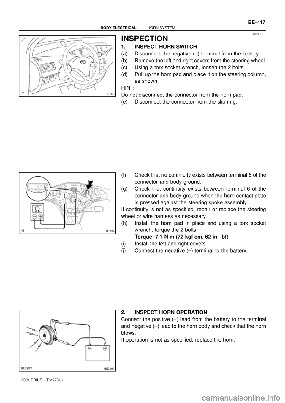
(a) Disconnect the negative (±) terminal from the battery.
(b) Remove the left and right covers from the steering wheel.
(c) Using a torx socket wrench, loosen the 2 bolts.
(d) Pull up the horn pad and place it on the steering column,
as shown.
HINT:
Do not disconnect the connector from the horn pad.
(e) Disconnect the connector from the slip ring.
(f) Check that no continuity exists between terminal 6 of the
connector and body ground.
(g) Check that continuity exists between terminal 6 of the
connector and body ground when the horn contact plate
is pressed against the steering spoke assembly.
If continuity is not as specified, repair or replace the steering
wheel or wire harness as necessary.
(h) Install the horn pad in place and using a torx socket
wrench, torque the 2 bolts.
Torque:
7.1 N´m (72 kgf´cm, 62 in.´lbf)
(i) Install the left and right covers.
(j) Connect the negative (±) terminal to the battery.
2. INSPECT HORN OPERATION
Connect the positive (+) lead from the battery to the terminal
and negative (±) lead to the horn body and check that the horn
blows.
If operation is not as specified, replace the horn.
Page 1881 of 1943
BO3TB±01
H15446
Passenger Airbag Assembly
Front Pillar Garnish
No. 2 Side Defroster Nozzle
No. 3 Register
Cluster Finish
Panel
Front Pillar
Garnish
Combination Meter
No. 1 Side Defroster Nozzle
Instrument Panel
No. 1 Register
Instrument Panel
Reinforcement
Upper Column Cover
Spiral Cable
Lower Column Cover
Lower Finish Panel
Front Door Scuff Plate
Cowl Side
TrimHood Lock Release LeverFront Door
Scuff Plate
Rear Console Box
Console Compartment
Door
Lower Center
Cluster Finish Panel
Glove Compartment
Door
Cowl Side Trim
Steering Wheel
Steering Wheel Pad
Finish Panel
No. 1 BraceCluster Finish
Panel Assembly
Radio Tuner Opening Cover
Hazard Warning Switch
N´m (kgf´cm, ft´lbf)
: Spesified torque
A
A
B
BNNC
HH
G
GG
G
D
D
II
G
G
D
D
I
O
50 (510, 37)
20 (204, 15)
KK
w/ Glove compartment door reinforcement:
Glove Compartment Door Reinforcement
L
L
HH
LL
EE
FF
± BODYINSTRUMENT PANEL
BO±59
1844 Author�: Date�:
2001 PRIUS (RM778U)
INSTRUMENT PANEL
COMPONENTS
Page 1884 of 1943

BO3TC±01
H154373 Clips
H154384 Clips
H15519
BO±62
± BODYINSTRUMENT PANEL
2001 PRIUS (RM778U)
REMOVAL
1. REMOVE STEERING WHEEL PAD AND STEERING
WHEEL (See page SR±4)
2. REMOVE FRONT DOOR SCUFF PLATES
3. REMOVE COWL SIDE TRIMS
4. REMOVE FRONT PILLAR GARNISHES
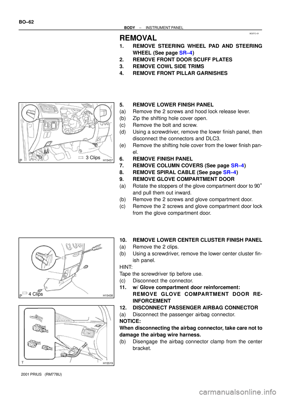
5. REMOVE LOWER FINISH PANEL
(a) Remove the 2 screws and hood lock release lever.
(b) Zip the shifting hole cover open.
(c) Remove the bolt and screw.
(d) Using a screwdriver, remove the lower finish panel, then
disconnect the connectors and DLC3.
(e) Remove the shifting hole cover from the lower finish pan-
el.
6. REMOVE FINISH PANEL
7. REMOVE COLUMN COVERS (See page SR±4)
8. REMOVE SPIRAL CABLE (See page SR±4)
9. REMOVE GLOVE COMPARTMENT DOOR
(a) Rotate the stoppers of the glove compartment door to 90°
and pull them out inward.
(b) Remove the 2 screws and glove compartment door.
(c) Remove the 2 screws and glove compartment door lock
from the glove compartment door.
10. REMOVE LOWER CENTER CLUSTER FINISH PANEL
(a) Remove the 2 clips.
(b) Using a screwdriver, remove the lower center cluster fin-
ish panel.
HINT:
Tape the screwdriver tip before use.
(c) Disconnect the connector.
11. w/ Glove compartment door reinforcement:
REMOVE GLOVE COMPARTMENT DOOR RE-
INFORCEMENT
12. DISCONNECT PASSENGER AIRBAG CONNECTOR
(a) Disconnect the passenger airbag connector.
NOTICE:
When disconnecting the airbag connector, take care not to
damage the airbag wire harness.
(b) Disengage the airbag connector clamp from the center
bracket.
Page 1915 of 1943
AC±10
± AIR CONDITIONINGAIR CONDITIONING SYSTEM
2001 PRIUS (RM778U)
4. INSPECT IDLE±UP SPEED
(a) Activate inspection mode (See page IN±10).
(b) Inspect idle±up speed when the these conditions are es-
tablished.
Test conditions:
�Idle speed set correctly.
�Steering wheel straight ahead
�Blower speed control dial at HI
�A/C switch ON
Magnetic clutch conditionIdle speed
Magnetic clutch not engaged1,000 ±50 rpm
Magnetic clutch engaged1,000 ±50 rpm
If idle speed is not as specified, check the engine ECU and
throttle body.
Page 1940 of 1943
I05156
RES/ACC
CANCEL
SET/COAST
4
3
I05126
CRUISE MAIN
Switch
43
± DIAGNOSTICSCRUISE CONTROL SYSTEM
DI±663
2001 PRIUS (RM778U)
2 Check control switch continuity.
PREPARATION:
(a) Remove steering wheel center pad.
(b) Disconnect the control switch connector.
CHECK:
Measure resistance between terminals 4 and 5 of control switch
connector when control switch is operated.
Switch positionResistance (W)
Neutral8 (No continuity)
RES/ACC220 ± 260
SET/COAST600 ± 660
CANCEL1,500 ± 1,600
NG Replace control switch.
OK
3 Check main switch continuity.
PREPARATION:
(a) Remove steering wheel center pad. (See page SR±6)
(b) Disconnect the control switch connector.
CHECK:
Check continuity between terminals 4 and 5 of control switch
connector when main switch is held ON and OFF.
OK:
Switch positionTester connectionSpecified condition
OFF±No continuity
Hold ON4 ± 5Continuity
NG Replace control switch.