Page 601 of 1943

SS13W±06
SS±26
± SERVICE SPECIFICATIONSSUSPENSION AND AXLE
148 Author�: Date�:
2001 PRIUS (RM778U)
SUSPENSION AND AXLE
SERVICE DATA
Cold tire inflation
pressureTire size: P175/65R14 84S Front
Rear240 kPa (2.4 kgf/cm2, 35 psi)
230 kPa (2.3 kgf/cm2, 33 psi)
Vehicle height
P175/65R14Front*1
Rear*2191 mm (7.52 in.)
239 mm (9.41 in.)
Camber
Right±left error±0°26' ± 45' (±0.43° ± 0.75°)
45' (0.75°) or less
Front wheel
Caster
Right±left error1°02' ± 45' (1.03° ± 0.75°)
45' (0.75°) or less
Front wheel
alignmentSteering axis inclination
Right±left error9°52' ± 45' (9.87° ± 0.75°)
45' (0.75°) or less
Toe±in (total)
Rack end length difference0°06' ± 12' (0.1° ± 0.2°, 1 ± 2 mm, 0.04± 0.08 in.)
1.5 mm (0.059 in.) or less
Wheel angle
Inside wheel
Outside wheel: Reference
42°42' ± 2° (42.70° ± 2°)
35°54' (35.90°)
Rear wheel
Camber
Right±left error±1°30' ± 45' (±0.93° ± 0.75°)
45' (0.75°) or less
Rear wheel
alignmentToe±in (total)0°06' ± 20' (0.1° ± 0.33°)
1 ± 3.0 mm (0.04 ± 0.12 in.)
FtlAxle bearing backlash Maximum0.05 mm (0.0020 in.)Front axleAxle hub deviationMaximum0.07 mm (0.0028 in.)
Front drive shaftDrive shaft standard length LH
RH579.9 ± 5.0 mm (22.831 ± 0.197 in.)
836.9 ± 5.0 mm (32.949 ± 0.197 in.)
Ft iLower suspension arm ball joint turning torque1.0 ± 4.9 N´m (10 ± 50 kgf´cm, 8.7 ± 43 in.´lbf)Front suspensionStabilizer bar link ball joint turning torque0.05 ± 1.0 N´m (0.5 ± 10 kgf´cm, 0.4 ± 8.7 in.´lbf)
RlAxle bearing backlash Maximum0.05 mm (0.0020 in.)Rear axleAxle hub deviationMaximum0.07 mm (0.0028 in.)
*1: Front measuring point
Measure the distance from the ground to the head center of the front side lower suspension arm mounting
bolt.
*2: Rear measuring point
Measure the distance from the ground to the center of the rear axle beam mounting bolt.
Page 604 of 1943

SS0LN±06
± SERVICE SPECIFICATIONSBRAKE
SS±29
2001 PRIUS (RM778U)
TORQUE SPECIFICATION
Part tightenedN´mkgf´cmft´lbf
BRAKE PEDAL
Pedal bracket x Reinforcement1414310
Brake pedal x Pedal bracket3737527
PARKING BRAKE PEDAL
Pedal bracket x Reinforcement1414310
Pedal bracket x Body131309
Brake pedal x Pedal bracket3232724
BRAKE MASTER CYLINDER
Master cylinder x Pedal bracket131309
Master cylinder clevis lock nut2626519
HYDRAULIC BRAKE BOOSTER
Hydraulic brake booster assembly x Body1919414
Sub±bracket x Body1919414
Reservoir bracket x Body1818413
Reservoir x Bracket7.57766 in.´lbf
Accumulator x Booster pump5455036
Pressure switch assembly x Brake power supply bracket7.88069 in.´lbf
Booster pump x Brake booster pump bracket No. 27.88069 in.´lbf
Pressure switch assembly x Brake booster pump bracket No. 17.88069 in.´lbf
Connector bracket x Pressure switch assembly7.88069 in.´lbf
Pressure switch assembly x Brake booster pump bracket No. 27.88069 in.´lbf
FRONT BRAKE
Front disc brake caliper installation bolt3435025
Bleeder plug8.38574 in.´lbf
Front disc brake caliper x Flexible hose3031022
Front disc brake torque plate x Steering knuckle1071,09079
REAR BRAKE
Bleeder plug8.58775 in.´lbf
Rear drum brake wheel cylinder x Backing plate101007
BRAKE ACTUATOR
Brake actuator assembly x Body1919514
Brake actuator x Actuator bracket111208
SPEED SENSOR
Front speed sensor installation bolt8.08271 in.´lbf
Front speed sensor harness clamp bolt5.55649 in.´lbf
Rear speed sensor harness clamp bolt5.55649 in.´lbf
BRAKE LINE
Brake line union nut1515511
Page 605 of 1943
SS16Y±09
SS±30
± SERVICE SPECIFICATIONSSTEERING
152 Author�: Date�:
2001 PRIUS (RM778U)
STEERING
SERVICE DATA
STEERING WHEEL
Steering wheel freeplayMaximum30 mm (1.18 in.)
Steering effort at idle speedReference6.5 N´m (65 kgf´cm, 58 in.´lbf)
Page 606 of 1943

SS16Z±08
± SERVICE SPECIFICATIONSSTEERING
SS±31
2001 PRIUS (RM778U)
TORQUE SPECIFICATION
Part tightenedN´mkgf´cmft´lbf
TILT STEERING COLUMN
Adjusting nut131309
No. 2 tilt lever lock bolt5.45548 in.´lbf
Tilt steering support lock nut9.510087 in.´lbf
Main shaft lower dust seal4.95043 in.´lbf
Column assembly set bolt and nut2526019
No. 2 intermediate shaft assembly x Main shaft assembly3536026
No. 2 intermediate shaft assembly x Intermediate extension3536026
Shift lock computer sub±assembly4.04035 in.´lbf
Steering wheel set nut5051037
Steering wheel pad set screw (Torx screw)8.89078 in.´lbf
POWER STEERING GEAR
Rack end x Steering rack62 (83)630 (850)46 (61)
Tie rod end lock nut5657041
PS gear assembly set bolt8385061
Stabilizer bar set bolt1919014
Suspension member137
1421,400
1,450101
105
Torque rod set nut1001,02074
EMPS bracket set bolt5.56052 in.´lbf
Lower suspension arm x Lower ball joint1421,450105
Stabilizer bar link set nut7476055
Tie rod end x Steering knuckle4950036
( ): For use without SST
Page 940 of 1943

F12396
TOYOTA
Hand±held Tester
DLC3
F09750
DLC3Tc
Ts
CG
BR3904
0.13 sec. 0.13 sec.
ON
OFF DI±360
± DIAGNOSTICSANTI±LOCK BRAKE SYSTEM WITH EBD & RBS
2001 PRIUS (RM778U)
(g) In case of using TOYOTA hand±held tester:
Clear the DTC.
(1) Hook up the TOYOTA hand±held tester to the
DLC3.
(2) Turn the ignition switch ON.
(3) Operate the TOYOTA hand±held tester to erase the
codes.
HINT:
Please refer to the TOYOTA hand±held tester operator's manu-
al for further details.
3. SENSOR SIGNAL CHECK (TEST MODE)
HINT:
If the ignition switch is turned from ON to ACC or LOCK during
test mode, DTC will be erased.
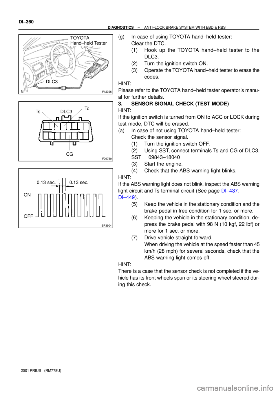
(a) In case of not using TOYOTA hand±held tester:
Check the sensor signal.
(1) Turn the ignition switch OFF.
(2) Using SST, connect terminals Ts and CG of DLC3.
SST 09843±18040
(3) Start the engine.
(4) Check that the ABS warning light blinks.
HINT:
If the ABS warning light does not blink, inspect the ABS warning
light circuit and Ts terminal circuit (See page DI±437,
DI±449).
(5) Keep the vehicle in the stationary condition and the
brake pedal in free condition for 1 sec. or more.
(6) Keeping the vehicle in the stationary condition, de-
press the brake pedal with 98 N (10 kgf, 22 lbf) or
more for 1 sec. or more.
(7) Drive vehicle straight forward.
When driving the vehicle at the speed faster than 45
km/h (28 mph) for several seconds, check that the
ABS warning light comes off.
HINT:
There is a case that the sensor check is not completed if the ve-
hicle has its front wheels spun or its steering wheel steered dur-
ing this check.
Page 1035 of 1943

F12396
TOYOTA
Hand±held Tester
DLC3
DI±462
± DIAGNOSTICSELECTRIC MOTOR POWER STEERING
2001 PRIUS (RM778U)
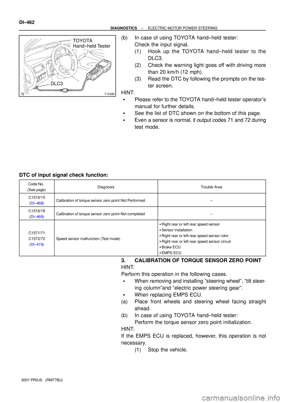
(b) In case of using TOYOTA hand±held tester:
Check the input signal.
(1) Hook up the TOYOTA hand±held tester to the
DLC3.
(2) Check the warning light goes off with driving more
than 20 km/h (12 mph).
(3) Read the DTC by following the prompts on the tes-
ter screen.
HINT:
�Please refer to the TOYOTA hand±held tester operator's
manual for further details.
�See the list of DTC shown on the bottom of this page.
�Even a sensor is normal, it output codes 71 and 72 during
test mode.
DTC of input signal check function:
Code No.
(See page)DiagnosisTrouble Area
C1515/15
(DI±468)Calibration of torque sensor zero point Not Performed±
C1516/16
(DI±469)Calibration of torque sensor zero point Not completed±
C1571/71
C1572/72
(DI±474)
Speed sensor malfunction (Test mode)
�Right rear or left rear speed sensor
�Sensor installation
�Right rear or left rear speed sensor rotor
�Right rear or left rear speed sensor circuit
�Brake ECU
�EMPS ECU
3. CALIBRATION OF TORQUE SENSOR ZERO POINT
HINT:
Perform this operation in the following cases.
�When removing and installing ºsteering wheelº, ºtilt steer-
ing columnºand ºelectric power steering gearº.
�When replacing EMPS ECU.
(a) Place front wheels and steering wheel facing straight
ahead.
(b) In case of using TOYOTA hand±held tester:
Perform the torque sensor zero point initialization.
HINT:
If the EMPS ECU is replaced, however, this operation is not
necessary.
(1) Stop the vehicle.
Page 1036 of 1943

F12396
TOYOTA
Hand±held Tester
DLC3
F12827
Tc
CG
Ts
F12864
Tc
CG
± DIAGNOSTICSELECTRIC MOTOR POWER STEERING
DI±463
2001 PRIUS (RM778U)
(2) Hook up the TOYOTA hand±held tester to the
DLC3.
(3) Select the ºTRQ SENS ADJUSTº mode on the TOY-
OTA hand±held tester.
(4) Select the ºZERO POINT INITIALIZEº.
(5) Following the screen instructions, perform the
torque sensor zero point initialization.
HINT:
Please refer to the TOYOTA hand±held tester operator's manu-
al for further details.
(c) In case of not using TOYOTA hand±held tester:
Perform the torque sensor zero point initialization.
HINT:
If the EMPS ECU is replaced, however, this operation is not
necessary.
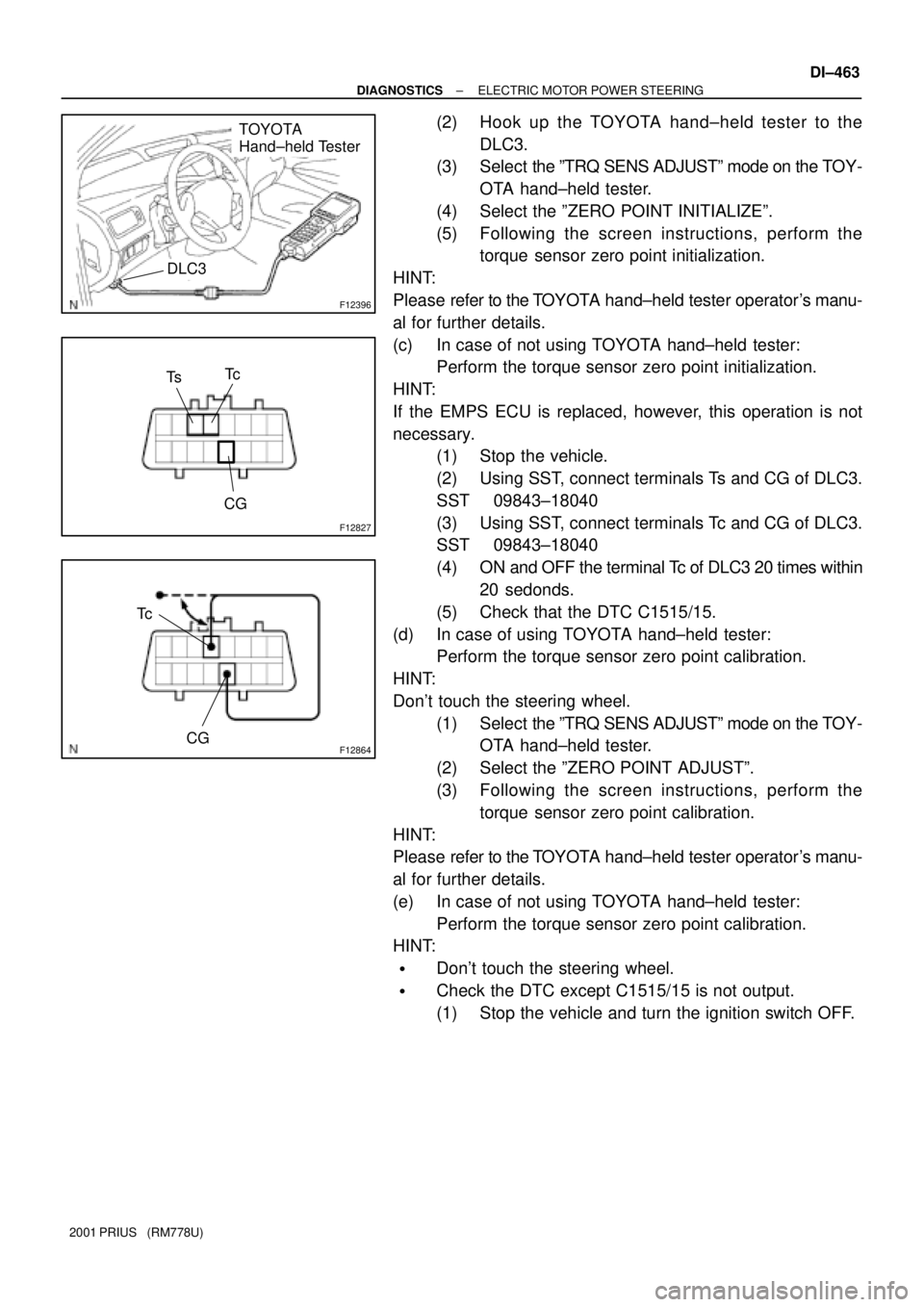
(1) Stop the vehicle.
(2) Using SST, connect terminals Ts and CG of DLC3.
SST 09843±18040
(3) Using SST, connect terminals Tc and CG of DLC3.
SST 09843±18040
(4) ON and OFF the terminal Tc of DLC3 20 times within
20 sedonds.
(5) Check that the DTC C1515/15.
(d) In case of using TOYOTA hand±held tester:
Perform the torque sensor zero point calibration.
HINT:
Don't touch the steering wheel.
(1) Select the ºTRQ SENS ADJUSTº mode on the TOY-
OTA hand±held tester.
(2) Select the ºZERO POINT ADJUSTº.
(3) Following the screen instructions, perform the
torque sensor zero point calibration.
HINT:
Please refer to the TOYOTA hand±held tester operator's manu-
al for further details.
(e) In case of not using TOYOTA hand±held tester:
Perform the torque sensor zero point calibration.
HINT:
�Don't touch the steering wheel.
�Check the DTC except C1515/15 is not output.
(1) Stop the vehicle and turn the ignition switch OFF.
Page 1045 of 1943
F12834
2
1DC Motor1
2
E4 E4 M1
M2EMPS ECU
B±YY
F12819
ON
M1
M2
DI±476
± DIAGNOSTICSELECTRIC MOTOR POWER STEERING
2001 PRIUS (RM778U)
DTCC1521/21±C1524/24Motor Circuit Malfunction
CIRCUIT DESCRIPTION
DTC No.Detection ItemTrouble Area
C1521/21
C1522/22Short circuit of motor terminal or abnormal voltage or current in�Power steering gear assembly with motor
C1523/23
Short circuit of motor terminal or abnormal voltage or current in
motor circuit.
�Power steering gear assembly with motor
�EMPS ECU
C1524/24
WIRING DIAGRAM
INSPECTION PROCEDURE
1 Check voltage between terminals M1 and M2 of EMPS ECU connector.
PREPARATION:
�Remove the EMPS ECU with connectors still connected.
�Turn the ignition switch ON.
CHECK:
Turn the steering wheel to left and right and measure the volt-
age between terminals M
1 and M2 of EMPS ECU connector.
OK:
Voltage: 9 ± 14 V
NG Check and replace the EMPS ECU.
DI7R4±01