Page 814 of 1943
A14146
BatteryB±G 1 1
F18 F13
Fusible Link
Block No. 2Hybrid Vehicle
Control ECU
H14
Engine Room J/B B
B J/C
1BFusible Link
Block No. 1
F12 B
1
MAIN 1F11
1 HV G±YJ2
J3G±Y
G±Y
IA143
BATT
± DIAGNOSTICSHYBRID VEHICLE CONTROL SYSTEM
DI±219
2001 PRIUS (RM778U)
DTC P1600 BATT Malfunction
CIRCUIT DESCRIPTION
Since the ECU back±up power source is used for DTC and freeze frame data memory, the back±up power
source (BATT) continues to be supplied to the HV ECU even though the ignition switch is turned OFF.
DTC P1600 ± Information code 117
INF. code.Detecting ConditionTrouble Area
11 7HV ECU back±up power source circuit malfunction�HV Fuse
�Wire harness
WIRING DIAGRAM
DI82T±02
Page 815 of 1943
DI±220
± DIAGNOSTICSHYBRID VEHICLE CONTROL SYSTEM
2001 PRIUS (RM778U)
INSPECTION PROCEDURE
1 Check continuity of HV fuse of engine room J/B.
OK:
Continuity
NG Check for short in all harness and parts con-
nected to HV fuse.
OK
Repair or replace wire harness.
Page 819 of 1943
DI±226
± DIAGNOSTICSHYBRID VEHICLE CONTROL SYSTEM
2001 PRIUS (RM778U)
DTC P3004 ± Information code 131
INF. Code.Detecting ConditionTrouble Area
131
When condition (a), (b) or (c) is detected:
(d) Main fuse blown out
(e) Service plug disconnected
(f) Limiter resistance cut off�Service plug
�Power cable
�System main relay
INSPECTION PROCEDURE
1 Is DTC of battery ECU being output?
YES Check the applicable DTC.
NO
2 Check condition of service plug terminal (Loosened, poor contact, etc.).
NG Replace service plug.
OK
3 Check continuity of power cable.
OK:
Continuity :Less than 1 W
NG Replace the power cable.
OK
Replace the system main relay.
Page 907 of 1943

A14089
B12009
F12396
DLC3
TOYOTA hand±held tester
± DIAGNOSTICSHV BATTERY CONTROL SYSTEM
DI±317
2001 PRIUS (RM778U)
(2) Inspect the auxiliary battery, fuses, fusible links, wir-
ing harness, connectors and ground.
(b) Check the master warning light.
(1) Turn the ignition switch ON and confirm that the
master warning light comes on.
HINT:
If the master warning light does not come on, suspect a burnt
fuse, burnt bulb, or open in wiring harness.
(2) When the ºREADYº light is ON, the master warning
light should go off.
If the lamp remains on, the diagnosis system has detected a
malfunction or abnormality in the system.
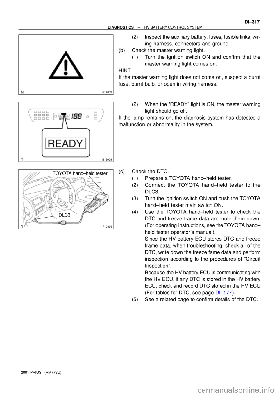
(c) Check the DTC.
(1) Prepare a TOYOTA hand±held tester.
(2) Connect the TOYOTA hand±held tester to the
DLC3.
(3) Turn the ignition switch ON and push the TOYOTA
hand±held tester main switch ON.
(4) Use the TOYOTA hand±held tester to check the
DTC and freeze frame data and note them down.
(For operating instructions, see the TOYOTA hand±
held tester operator's manual).
Since the HV battery ECU stores DTC and freeze
frame data, when troubleshooting, check all of the
DTC, write down the freeze fame data and perform
inspection according to the procedures of ºCircuit
Inspectionº.
Because the HV battery ECU is communicating with
the HV ECU, if any DTC is stored in the HV battery
ECU, check and record DTC stored in the HV ECU
(For tables for DTC, see page DI±177).
(5) See a related page to confirm details of the DTC.
Page 911 of 1943

A14081
AM
A14082
Engine Room J/B
HV Fuse
DI±324
± DIAGNOSTICSHV BATTERY CONTROL SYSTEM
2001 PRIUS (RM778U)
INSPECTION PROCEDURE
HINT:
Read freeze frame data using a TOYOTA hand±held tester or OBD II scan tool. Because freeze frame data
records the battery condition when the malfunction is detected. When troubleshooting, this is useful for
knowing the battery condition.
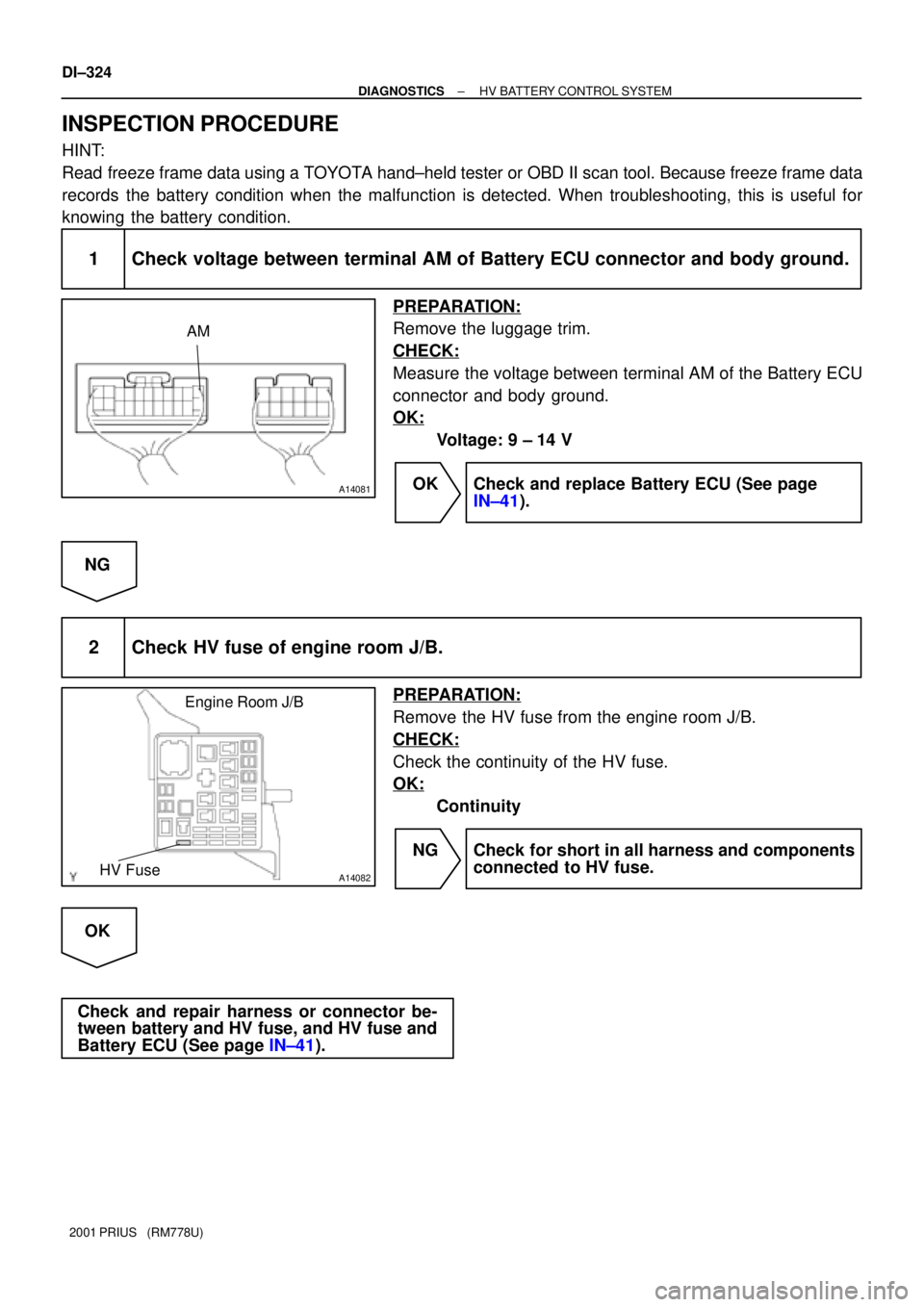
1 Check voltage between terminal AM of Battery ECU connector and body ground.
PREPARATION:
Remove the luggage trim.
CHECK:
Measure the voltage between terminal AM of the Battery ECU
connector and body ground.
OK:
Voltage: 9 ± 14 V
OK Check and replace Battery ECU (See page
IN±41).
NG
2 Check HV fuse of engine room J/B.
PREPARATION:
Remove the HV fuse from the engine room J/B.
CHECK:
Check the continuity of the HV fuse.
OK:
Continuity
NG Check for short in all harness and components
connected to HV fuse.
OK
Check and repair harness or connector be-
tween battery and HV fuse, and HV fuse and
Battery ECU (See page IN±41).
Page 914 of 1943
A13558
Power Cable
to System Main Relay,
InverterBattery ECU
Service Plug Assembly
High Voltage Fuse
Service Plug
Power CableBattery Block No. 10L±W
L
76
to System Main Relay,
Inverter
DI±328
± DIAGNOSTICSHV BATTERY CONTROL SYSTEM
2001 PRIUS (RM778U)
DTC P3005 High Voltage Fuse Snapped
CIRCUIT DESCRIPTION
A fuse is set in the service plug to protect high±voltage system parts.
DTC No.DTC Detecting ConditionTrouble Area
P3005Although interlock switch is connected, voltage of battery block
No. 10 is less than specified.�High voltage fuse
�Power cable
WIRING DIAGRAM
DI827±01
Page 915 of 1943
± DIAGNOSTICSHV BATTERY CONTROL SYSTEM
DI±329
2001 PRIUS (RM778U)
INSPECTION PROCEDURE
1 Are there any other codes (besides DTC P3005) and other ECU being output?
YES Go to relevant DTC chart.
NO
2 Check continuity of high voltage fuse in the service plug assembly and check
condition of service plug terminal (Loosened, poor contact, etc.).
OK Repair or replace the power cable.
NG
Repair or replace the service plug or the high
voltage fuse in the service plug assembly.
Page 934 of 1943
A14084
Engine Room J/B
FAN Fuse
DI±352
± DIAGNOSTICSHV BATTERY CONTROL SYSTEM
2001 PRIUS (RM778U)
INSPECTION PROCEDURE
1 Check FAN fuse of engine room J/B.
PREPARATION:
Remove the FAN fuse from the engine room J/B.
CHECK:
Check the continuity of the FAN fuse.
OK:
Continuity
NG Check for short in all harness and components
connected to FAN fuse. Check that the motor is
not locked. If locked, replace the motor.
OK
2 Check blower fan relay (See page HV±35).
NG Replace the blower fan relay.
OK
3 Check blower motor operation.
PREPARATION:
Remove the blower motor (See page HV±32).
CHECK:
Apply battery voltage to the power supply terminal of the motor, and check the fan rotation.
OK:
The fan rotates normally.
NG Replace the blower motor.
OK
Replace battery blower motor controller.