Page 743 of 1943
A13634
LOCK
BATT
(±)
(+)
A13630
Engine Room J/B
EFI Fuse
DI±144
± DIAGNOSTICSENGINE
2001 PRIUS (RM778U)
1 Check voltage between terminal BATT of ECM connector and body ground.
PREPARATION:
Remove the ECM with connector still connected (See page
SF±62).
CHECK:
Measure voltage between terminal BATT of the ECM connector
and body ground.
OK:
Voltage: 9 ± 14 V
OK Check and replace ECM (See page IN±41).
NG
2 Check EFI fuse.
PREPARATION:
Remove the EFI fuse from the engine room J/B.
CHECK:
Check continuity of EFI fuse.
OK:
Continuity
NG Check for short in all the harness and
components connected to EFI fuse.
OK
Check and repair harness or connector
between battery and EFI fuse and ECM
(See page IN±41).
Page 756 of 1943
A13630
Engine Room J/B
AM2 Fuse
DI±158
± DIAGNOSTICSENGINE
2001 PRIUS (RM778U)
4 Check AM2 fuse.
PREPARATION:
Remove the AM2 fuse from the engine room J/B.
CHECK:
Check the continuity of the AM2 fuse.
OK:
Continuity
NG Check for short in all harness and components
connected to AM2 fuse (See attached wiring dia-
gram).
OK
5 Check ignition switch (See page BE±16).
NG Replace ignition switch.
OK
Check and repair harness and connector be-
tween battery and ignition switch, and igni-
tion switch and ECM.
Page 757 of 1943
A14004
MREL
(+) (±)
A13630
Engine Room J/B
EFI Fuse
± DIAGNOSTICSENGINE
DI±159
2001 PRIUS (RM778U)
6 Check voltage between terminal MREL of ECM connector and body ground.
PREPARATION:
(a) Remove the ECM with connector still connected (See
page SF±62).
(b) Turn the ignition switch ON.
CHECK:
Measure the voltage between terminal MREL of the ECM con-
nector and body ground.
OK:
Voltage: 9 ± 14 V
NG Check and replace ECM (See page IN±41).
OK
7 Check EFI1 fuse.
PREPARATION:
Remove the EFI fuse from the engine room J/B.
CHECK:
Check continuity of EFI fuse.
OK:
Continuity
NG Check for short in all harness and components
connected to EFI1 fuse (See attached wiring
diagram).
OK
8 Check EFI main relay (Marking: EFI MAIN) (See page SF±37).
NG Replace EFI main relay.
OK
Page 758 of 1943
DI±160
± DIAGNOSTICSENGINE
2001 PRIUS (RM778U)
9 Check for open and short in harness and connector between terminal MREL of
ECM and body ground (See page IN±41).
NG Repair or replace harness or connector.
OK
Check and repair harness or connector be-
tween EFI1 fuse and battery.
Page 775 of 1943

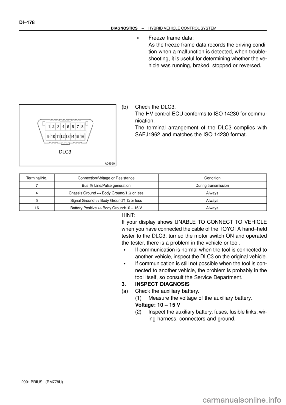
A04550
DLC3
912 3 4 56 78
16 15 14 13 12 11 10
DI±178
± DIAGNOSTICSHYBRID VEHICLE CONTROL SYSTEM
2001 PRIUS (RM778U)
�Freeze frame data:
As the freeze frame data records the driving condi-
tion when a malfunction is detected, when trouble-
shooting, it is useful for determining whether the ve-
hicle was running, braked, stopped or reversed.
(b) Check the DLC3.
The HV control ECU conforms to ISO 14230 for commu-
nication.
The terminal arrangement of the DLC3 complies with
SAEJ1962 and matches the ISO 14230 format.
Terminal No.Connection/Voltage or ResistanceCondition
7Bus � Line/Pulse generationDuring transmission
4Chassis Ground e Body Ground/1 W or lessAlways
5Signal Ground e Body Ground/1 W or lessAlways
16Battery Positive e Body Ground/10 ± 15 VAlways
HINT:
If your display shows UNABLE TO CONNECT TO VEHICLE
when you have connected the cable of the TOYOTA hand±held
tester to the DLC3, turned the motor switch ON and operated
the tester, there is a problem in the vehicle or tool.
�If communication is normal when the tool is connected to
another vehicle, inspect the DLC3 on the original vehicle.
�If communication is still not possible when the tool is con-
nected to another vehicle, the problem is probably in the
tool itself, so consult the Service Department.
3. INSPECT DIAGNOSIS
(a) Check the auxiliary battery.
(1) Measure the voltage of the auxiliary battery.
Voltage: 10 ± 15 V
(2) Inspect the auxiliary battery, fuses, fusible links, wir-
ing harness, connectors and ground.
Page 776 of 1943

A14089
B12009
F12396
DLC3
TOYOTA Hand±held Tester
± DIAGNOSTICSHYBRID VEHICLE CONTROL SYSTEM
DI±179
2001 PRIUS (RM778U)
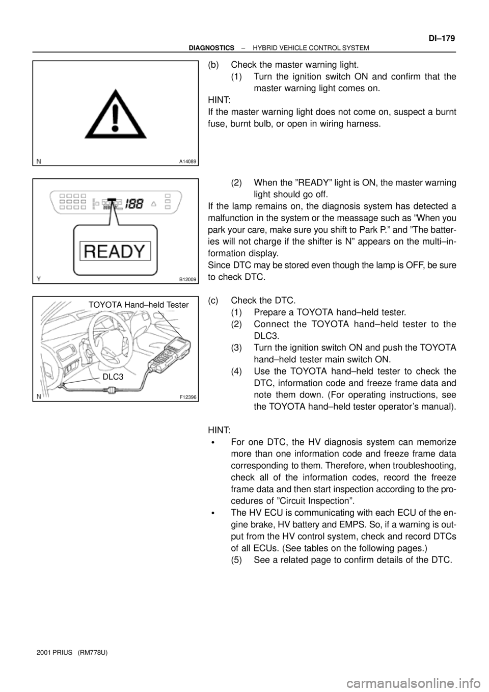
(b) Check the master warning light.
(1) Turn the ignition switch ON and confirm that the
master warning light comes on.
HINT:
If the master warning light does not come on, suspect a burnt
fuse, burnt bulb, or open in wiring harness.
(2) When the ºREADYº light is ON, the master warning
light should go off.
If the lamp remains on, the diagnosis system has detected a
malfunction in the system or the meassage such as ºWhen you
park your care, make sure you shift to Park P.º and ºThe batter-
ies will not charge if the shifter is Nº appears on the multi±in-
formation display.
Since DTC may be stored even though the lamp is OFF, be sure
to check DTC.
(c) Check the DTC.
(1) Prepare a TOYOTA hand±held tester.
(2) Connect the TOYOTA hand±held tester to the
DLC3.
(3) Turn the ignition switch ON and push the TOYOTA
hand±held tester main switch ON.
(4) Use the TOYOTA hand±held tester to check the
DTC, information code and freeze frame data and
note them down. (For operating instructions, see
the TOYOTA hand±held tester operator's manual).
HINT:
�For one DTC, the HV diagnosis system can memorize
more than one information code and freeze frame data
corresponding to them. Therefore, when troubleshooting,
check all of the information codes, record the freeze
frame data and then start inspection according to the pro-
cedures of ºCircuit Inspectionº.
�The HV ECU is communicating with each ECU of the en-
gine brake, HV battery and EMPS. So, if a warning is out-
put from the HV control system, check and record DTCs
of all ECUs. (See tables on the following pages.)
(5) See a related page to confirm details of the DTC.
Page 794 of 1943

DI82L±02
± DIAGNOSTICSHYBRID VEHICLE CONTROL SYSTEM
DI±197
2001 PRIUS (RM778U)
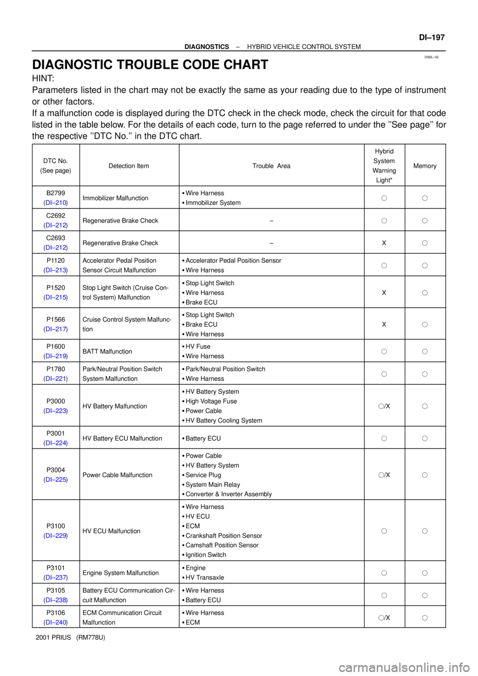
DIAGNOSTIC TROUBLE CODE CHART
HINT:
Parameters listed in the chart may not be exactly the same as your reading due to the type of instrument
or other factors.
If a malfunction code is displayed during the DTC check in the check mode, check the circuit for that code
listed in the table below. For the details of each code, turn to the page referred to under the ''See page'' for
the respective ''DTC No.'' in the DTC chart.
DTC No.
(See page)Detection ItemTrouble Area
Hybrid
System
Warning
Light*
Memory
B2799
(DI±210)Immobilizer Malfunction�Wire Harness
�Immobilizer System��
C2692
(DI±212)Regenerative Brake Check±��
C2693
(DI±212)Regenerative Brake Check±X�
P1120
(DI±213)Accelerator Pedal Position
Sensor Circuit Malfunction�Accelerator Pedal Position Sensor
�Wire Harness��
P1520
(DI±215)Stop Light Switch (Cruise Con-
trol System) Malfunction�Stop Light Switch
�Wire Harness
�Brake ECU
X�
P1566
(DI±217)Cruise Control System Malfunc-
tion�Stop Light Switch
�Brake ECU
�Wire Harness
X�
P1600
(DI±219)BATT Malfunction�HV Fuse
�Wire Harness��
P1780
(DI±221)Park/Neutral Position Switch
System Malfunction�Park/Neutral Position Switch
�Wire Harness��
P3000
(DI±223)HV Battery Malfunction
�HV Battery System
�High Voltage Fuse
�Power Cable
�HV Battery Cooling System
�/X�
P3001
(DI±224)HV Battery ECU Malfunction�Battery ECU��
P3004
(DI±225)Power Cable Malfunction
�Power Cable
�HV Battery System
�Service Plug
�System Main Relay
�Converter & Inverter Assembly
�/X�
P3100
(DI±229)HV ECU Malfunction
�Wire Harness
�HV ECU
�ECM
�Crankshaft Position Sensor
�Camshaft Position Sensor
�Ignition Switch
��
P3101
(DI±237)Engine System Malfunction�Engine
�HV Transaxle��
P3105
(DI±238)Battery ECU Communication Cir-
cuit Malfunction�Wire Harness
�Battery ECU��
P3106
(DI±240)ECM Communication Circuit
Malfunction�Wire Harness
�ECM�/X�
Page 796 of 1943

± DIAGNOSTICSHYBRID VEHICLE CONTROL SYSTEM
DI±199
2001 PRIUS (RM778U)
INFORMATION CODE (TOYOTA Hand±held tester only)
DTC NO.INF. CodeDetection ItemDetecting Condition
B2799101Immobilizer MalfunctionNo input of signal from transponder key ECU
C2692102Regenerative Brake CheckRegenerative brake check
C2693103Regenerative Brake CheckRegenerative brake check
104Open or short in main accelerator sensor circuit
105+B short in main accelerator sensor circuit
106Main sensor internal error
107Open or short in sub accelerator sensor circuit
108+B short in sub accelerator sensor circuit
P1120109Accelerator Pedal Position
Sensor Circuit MalfunctionSub sensor internal errorP1120
11 0Sensor Circuit MalfunctionWhen difference between main sensor value and sub sensor value is large
111When sub sensor value changes while main sensor value does not
11 2When main sensor value changes while sub sensor value does not
11 3When any of the information code 104 ± 112 continues to appear
11 4Accelerator pedal not smoothly returning to original position
P152011 5
Stop Light Switch
(Cruise Control System)
Malfunction
Open or short in stop light switch circuit
P156611 6Cruise Control System
MalfunctionWhen STP signal of HV ECU is inconsistent with that of brake ECU, with
cruise control indicator ON
P160011 7BATT MalfunctionHV ECU back±up power source circuit malfunction
11 8When more than 2 main signals are ON
11 9P k/N t l P iti S it hWhen main signal is not turned ON even though sub signal has been input
P1780120Park/Neutral Position Switch
System MalfunctionOpen or short in sub sensor circuit
121
System Malfunction
When shift position detected by main signal is different from that detected
by sub signal
123HV B tt M lf tiInput of abnormal signal from battery ECU (HV battery system malfunction)
125HV Battery MalfunctionInput of abnormal signal from battery ECU (high voltage fuse blown out)
P3000388Discharge Inhibition Control
MalfunctionWhen charged battery is low due to leaving the vehicle in N position, gas
shortage or HV system malfunction
389Drop of High VoltageWhen main battery is dead or main battery is dead due to HV system mal-
function
P3001129HV Battery ECU MalfunctionBattery ECU malfunction
130HV Battery MalfunctionWhen HV battery voltage becomes lower than inverter voltage
P3004
131
PCblMlfti
When main fuse is blown out, service plug is disconnected or limiter resis-
tance is cut off
P3004
132
Power Cable MalfunctionWhen inverter voltage sensor is malfunctioning or limiter resistance value
increases
133HV Battery MalfunctionInput of abnormal signal from battery ECU
134HV ECU I t l EHV ECU Internal Error
135HV ECU Internal ErrorHV ECU Internal Error
P3100136GO Signal ErrorOpen or short in GO signal circuit
137Engine Speed Sensor
MalfunctionEngine speed sensor malfunction