Page 336 of 1943

THS (TOYOTA HYBRID SYSTEM)
Battery Voltage for Each
Module
HV Battery Temp. Sensor
Temp. Sensor (Circumference)
Amperage sensor
A / C Signal
Battery ECU
A / C ECU
HV Battery Cooling Fan
HV ECU
�Amperage Signal
�Total Voltage Signal
�Charge or Discharge Signal
�DiagnosisData Link Connector 3
182TH11
HV Battery
SMR2
Battery Module
(7.2 V x 19)
Service Plug
High-Voltage Fuse
Battery Module
(7.2 V x 19)
SMR3
Resistor SMR1
38
HV BATTERY CONTROL SYSTEM
�DESCRIPTION
To maintain the battery at a proper SOC (state of charge), and to ensure safety in the event that the HV battery
malfunctions, the battery ECU features the following control functions:
� System Diagram �
�CONSTRUCTION
�The HV battery, battery ECU, and SMR (sys-
tem main relay), are enclosed in a single case
and placed in the luggage compartment behind
the rear seat to make more effective use of ve-
hicle space.
�In the battery area, six 1.2-volt cells are con-
nected in series to form one module. A total of
38 modules are connected in series.
Thus, the HV battery containing a total of 228
cells has a rated voltage of 273.6 V.
�A service plug that shuts off the circuit is pro-
vided in the middle of the 38 modules. Before
servicing any portion of the high-voltage cir-
cuit, make sure to remove the service plug. For
further details, refer to the 2001 Prius Repair
Manual (Pub No. RM778U).
Page 338 of 1943

THS (TOYOTA HYBRID SYSTEM)
182TH11
HV Battery
SMR 2
SMR 1
Battery Module
(7.2 V x 19)
Resistor
Service Plug
High-Voltage Fuse
Battery Module
(7.2 V x 19)
SMR 3
182TH30
Service Plug 40
2. SMR (System Main Relay)
The SMR is a relay that connects and disconnects
the power source of the high-voltage circuit upon
receiving a command from the HV ECU. A total
of 3 relays, one for the negative side, and two for
the positive side, are provided to ensure proper op-
erations.
At the time of connection, SMR1 and SMR3 are
turned ON; after this, SMR2 is turned ON and
SMR1 is turned OFF. By allowing the controlled
current via the resistor to pass through initially in
this manner, the circuit is protected against rush
current.
At the time of disconnection, SMR2 and SMR3
are turned OFF in that order, and the HV ECU ver-
ifies that the respective relays have been properly
turned OFF.
3. Service Plug
By removing the service plug before performing any inspection or service, the high-voltage circuit is shut
off at the intermediate position of the HV battery, thus ensuring safety during service.
The service plug assembly contains a reed switch for interlock. Lifting the clip lock up turns OFF the reed
switch, which shuts off the SMR. However, to ensure safety, make sure to turn OFF the ignition switch before
removing the service plug. For further details on how to handle the service plug, refer to the 2001 Prius Repair
Manual (Pub No. RM778U). The main fuse for the high-voltage circuit is provided inside of the service plug
assembly.
Page 458 of 1943
BE1367
Medium Current Fuse and High Current Fuse
Equal Amperage Rating
V00076
Abbreviation Part Name Symbol Illustration
FUSE
MEDIUM CURRENT FUSE
HIGH CURRENT FUSE
FUSIBLE LINK
CIRCUIT BREAKERFUSE
M±FUSE
H±FUSE
FL
CB
± INTRODUCTIONREPAIR INSTRUCTIONS
IN±5
5 Author�: Date�:
2001 PRIUS (RM778U)
(3) Precoated parts are indicated in the component il-
lustrations by the º�º symbol.
(g) When necessary, use a sealer on gaskets to prevent
leaks.
(h) Carefully observe all specifications for bolt tightening
torques. Always use a torque wrench.
(i) Use of special service tools (SST) and special service ma-
terials (SSM) may be required, depending on the nature
of the repair. Be sure to use SST and SSM where speci-
fied and follow the proper work procedure. A list of SST
and SSM can be found in Preparation section in this
manual.
(j) When replacing fuses, be sure the new fuse has the cor-
rect amperage rating. DO NOT exceed the rating or use
one with a lower rating.
Page 471 of 1943

B04757
B04752
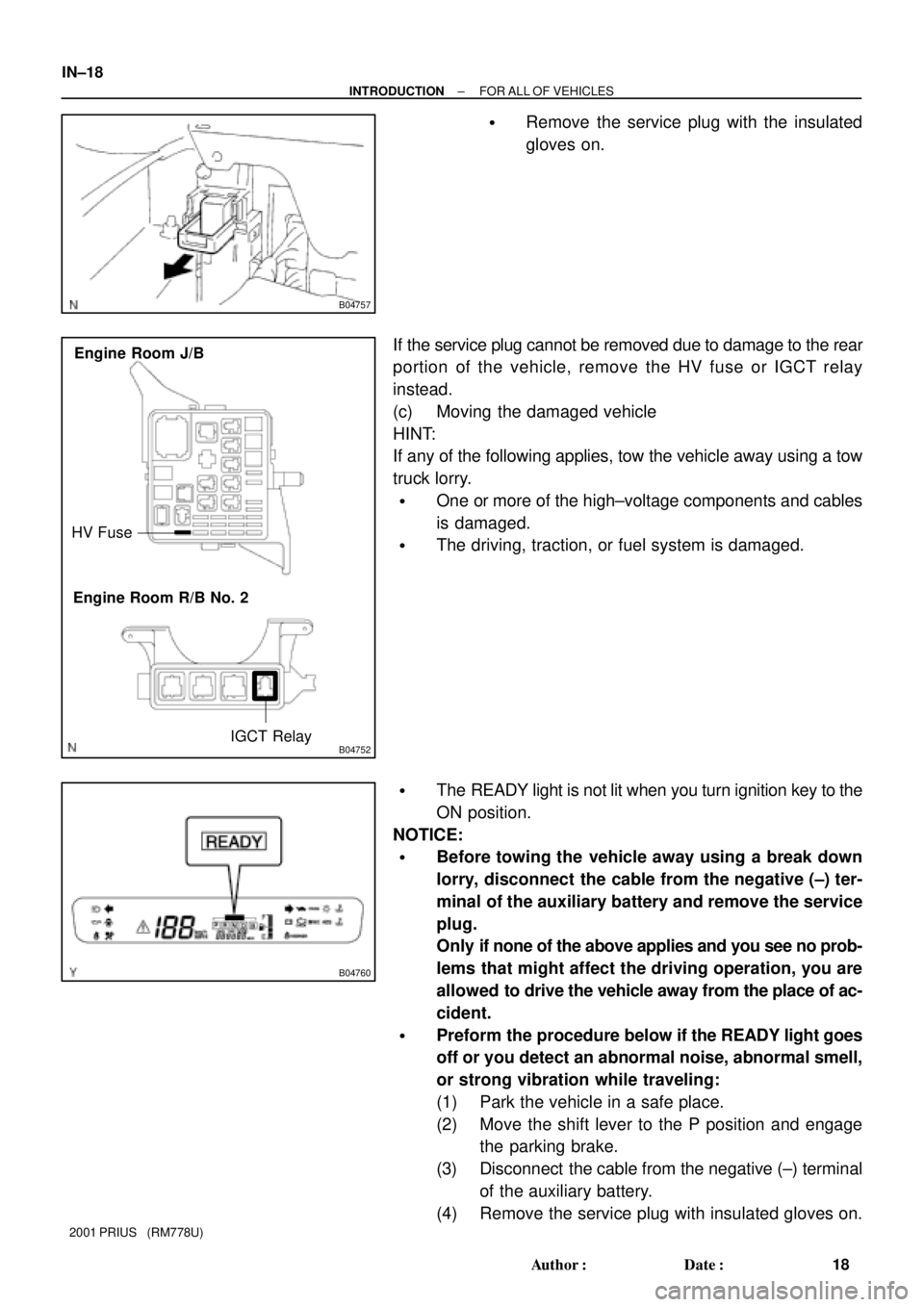
HV Fuse
IGCT Relay Engine Room J/B
Engine Room R/B No. 2
B04760
IN±18
± INTRODUCTIONFOR ALL OF VEHICLES
18 Author�: Date�:
2001 PRIUS (RM778U)
�Remove the service plug with the insulated
gloves on.
If the service plug cannot be removed due to damage to the rear
portion of the vehicle, remove the HV fuse or IGCT relay
instead.
(c) Moving the damaged vehicle
HINT:
If any of the following applies, tow the vehicle away using a tow
truck lorry.
�One or more of the high±voltage components and cables
is damaged.
�The driving, traction, or fuel system is damaged.
�The READY light is not lit when you turn ignition key to the
ON position.
NOTICE:
�Before towing the vehicle away using a break down
lorry, disconnect the cable from the negative (±) ter-
minal of the auxiliary battery and remove the service
plug.
Only if none of the above applies and you see no prob-
lems that might affect the driving operation, you are
allowed to drive the vehicle away from the place of ac-
cident.
�Preform the procedure below if the READY light goes
off or you detect an abnormal noise, abnormal smell,
or strong vibration while traveling:
(1) Park the vehicle in a safe place.
(2) Move the shift lever to the P position and engage
the parking brake.
(3) Disconnect the cable from the negative (±) terminal
of the auxiliary battery.
(4) Remove the service plug with insulated gloves on.
Page 473 of 1943

B04758
IN±20
± INTRODUCTIONFOR ALL OF VEHICLES
20 Author�: Date�:
2001 PRIUS (RM778U)
(6) If a damage to any of the high±voltage components
and cables is suspected, cut the high±voltage cir-
cuit using the procedure below:
�Move the shift lever to the P position and en-
gage the parking brake.
�Remove the ignition key. Then disconnect the
cable from the negative (±) terminal of the
auxiliary battery.
�Wear insulated gloves, and then remove the
service plug.
�If you cannot remove the service plug due to
damage to the rear portion of the vehicle, re-
move the HV fuse or IGCT relay instead.
(g) Precautions to be taken when disposing of the vehicle
When scrapping the vehicle, remove the HV battery from
the vehicle and return it through the route specified by the
manufacturer. The same applies to any damaged HV bat-
tery.
(h) Precautions to be observed when towing
Tow the damaged vehicle with its front wheels or its front
and rear wheels lifted off the ground.
NOTICE:
Towing the damaged vehicle with its front wheels on the
ground may cause the motor to generate electricity. This
electricity could, depending on the nature of the damage,
leak and cause a fire.
(i) Towing with 4 wheels on the ground
NOTICE:
�If you have to tow the damaged vehicle using a rope,
do it at a speed below 30 km/h. Such towing operation
is allowed only to cover very short distance, such as
the distance to a tow truck lorry, for example.
�Set the ignition switch to the ACC position and shift
lever to the N position.
�If you detect any abnormality in the damaged vehicle
during the towing operation, stop the towing opera-
tion immediately.
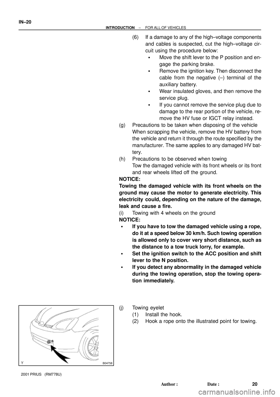
(j) Towing eyelet
(1) Install the hook.
(2) Hook a rope onto the illustrated point for towing.
Page 501 of 1943

IN±48
± INTRODUCTIONTERMS
48 Author�: Date�:
2001 PRIUS (RM778U) H/B
Hatchback
H±FUSEHigh Current Fuse
HIHigh
HIDHigh Intensity Discharge (Head Lamp)
HSGHousing
HTHard Top
HVHybrid Vehicle
HWSHeated Windshield System
IACIdle Air Control
ICIntegrated circuit
IDIIndirect Diesel Injection
IFSIndependent Front Suspension
IGIgnition
IIAIntegrated Ignition Assembly
INIntake (Manifold, Valve)
INTIntermittent
I/PInstrument Panel
IRSIndependent Rear Suspension
J/BJunction Block
J/CJunction Connector
KDKick±Down
LANLocal Area Network
LBLiftback
LCDLiquid Crystal Display
LEDLight Emitting Diode
LHLeft±Hand
LHDLeft±Hand Drive
L/H/WLength, Height, Width
LLCLong±Life Coolant
LNGLiquified Natural Gas
LOLow
LPGLiquified Petroleum Gas
LSDLimited Slip Differential
LSP & PVLoad Sensing Proportioning And Bypass Valve
LSPVLoad Sensing Proportioning Valve
MAX.Maximum
MG1Motor Generator No. 1
MG2Motor Generator No. 2
MICMicrophone
MILMalfunction Indicator Lamp
MIN.Minimum
MPMultipurpose
MPXMultiplex Communication System
M/TManual Transmission
MTMount
MTGMounting
Page 614 of 1943

DI±6
± DIAGNOSTICSENGINE
2001 PRIUS (RM778U)
�TOYOTA hand±held tester only:
When the diagnosis system is switched from normal
mode to check mode, it erases all DTCs and freezed
frame data recorded in normal mode. So before
switching modes, always check the DTCs and
freezed frame data, and note them down.
(1) Prepare the TOYOTA hand±held tester or OBDII
scan tool (complying with SAE J1978).
(2) Connect the TOYOTA hand±held tester or OBDII
scan tool to DLC3 under the instrument panel lower
pad.
(3) Turn the ignition switch ON and turn the TOYOTA
hand±held tester or OBDII scan tool switch ON.
(4) Use the TOYOTA hand±held tester or OBDII scan
tool to check the DTCs and freezed frame data;
note them down. (For operating instructions, see
the OBDII scan tool's instruction book.)
(5) See step 4 to confirm the details of the DTCs.
NOTICE:
�When simulating symptoms with an OBDII scan tool
(excluding TOYOTA hand±held tester) to check the
DTCs, use normal mode. For code on the DTC chart
subject to º2 trip detection logicº, perform the follow-
ing either action.
�Turn the ignition switch OFF after the symptom is
simulated the first time. Then repeat the simulation
process again. When the problem has been simulated
twice, the MIL lights up and the DTCs are recorded in
the ECM.
�Check the 1st trip DTC using Mode 7 (Continuous Test
Results) for SAE J1979.
(c) Clear the DTC.
The DTCs and freezed frame data will be erased by either
action.
(1) Operating the TOYOTA hand±held tester or OBDII
scan tool (complying with SAE J1978) to erase the
codes. (See the OBDII scan tool's instruction book
for operating instructions.)
(2) Disconnecting the battery terminals or EFI fuse.
NOTICE:
If the TOYOTA hand±held tester switches the ECM from the
normal mode to the check mode or vice±versa, or if the
ignition switch is turned from ON to ACC or OFF during
check mode, the DTCs and freezed frame data will be
erased.
Page 713 of 1943
A13630THRO FuseR/B No.2
A13631
BM
(+)(±)
± DIAGNOSTICSENGINE
DI±111
2001 PRIUS (RM778U)
1 Check THRO fuse of R/B No.2.
PREPARATION:
Remove the THRO fuse from the Engine room J/B.
CHECK:
Check the countinuity of the THRO fuse.
OK:
Continuity
NG Check for short in all harness and components
connected to THRO fuse.
OK
2 Check voltage between terminal +BM of ECM connector and body ground.
PREPARATION:
Remove the ECM with connector still connected (See page
SF±62).
CHECK:
Measure the voltage between terminal BM of the ECM connec-
tor and body ground.
OK:
Voltage: 9 ± 14 V
OK Check and replace ECM (See page IN±41).
NG
Check and repair harness or connector be-
tween battery and ETCS fuse, and ETCS fuse
and ECM (See page IN±41).