2001 TOYOTA PRIUS fuse
[x] Cancel search: fusePage 131 of 1943
2001 PRIUS (EWD414U)
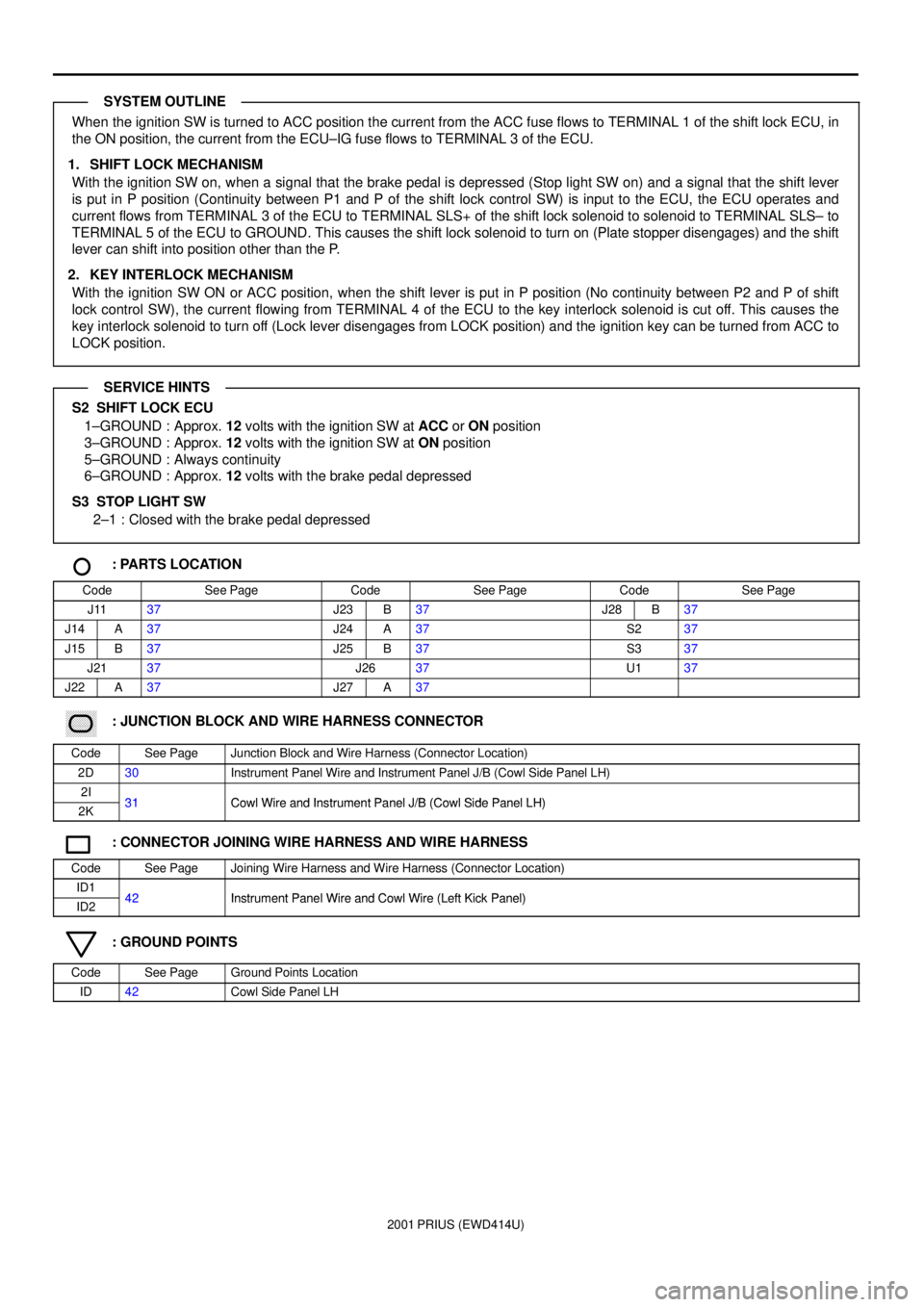
When the ignition SW is turned to ACC position the current from the ACC fuse flows to TERMINAL 1 of the shift lock ECU, in
the ON position, the current from the ECU±IG fuse flows to TERMINAL 3 of the ECU.
1. SHIFT LOCK MECHANISM
With the ignition SW on, when a signal that the brake pedal is depressed (Stop light SW on) and a signal that the shift lever
is put in P position (Continuity between P1 and P of the shift lock control SW) is input to the ECU, the ECU operates and
current flows from TERMINAL 3 of the ECU to TERMINAL SLS+ of the shift lock solenoid to solenoid to TERMINAL SLS± to
TERMINAL 5 of the ECU to GROUND. This causes the shift lock solenoid to turn on (Plate stopper disengages) and the shift
lever can shift into position other than the P.
2. KEY INTERLOCK MECHANISM
With the ignition SW ON or ACC position, when the shift lever is put in P position (No continuity between P2 and P of shift
lock control SW), the current flowing from TERMINAL 4 of the ECU to the key interlock solenoid is cut off. This causes the
key interlock solenoid to turn off (Lock lever disengages from LOCK position) and the ignition key can be turned from ACC to
LOCK position.
S2 SHIFT LOCK ECU
1±GROUND : Approx. 12 volts with the ignition SW at ACC or ON position
3±GROUND : Approx. 12 volts with the ignition SW at ON position
5±GROUND : Always continuity
6±GROUND : Approx. 12 volts with the brake pedal depressed
S3 STOP LIGHT SW
2±1 : Closed with the brake pedal depressed
: PARTS LOCATION
CodeSee PageCodeSee PageCodeSee Page
J1137J23B37J28B37
J14A37J24A37S237
J15B37J25B37S337
J2137J2637U137
J22A37J27A37
������ ���: JUNCTION BLOCK AND WIRE HARNESS CONNECTOR
CodeSee PageJunction Block and Wire Harness (Connector Location)
2D30Instrument Panel Wire and Instrument Panel J/B (Cowl Side Panel LH)
2I31Cowl Wire and Instrument Panel J/B (Cowl Side Panel LH)2K31Cowl Wire and Instrument Panel J/B (Cowl Side Panel LH)
: CONNECTOR JOINING WIRE HARNESS AND WIRE HARNESS
CodeSee PageJoining Wire Harness and Wire Harness (Connector Location)
ID142Instrument Panel Wire and Cowl Wire (Left Kick Panel)ID242Instrument Panel Wire and Cowl Wire (Left Kick Panel)
: GROUND POINTS
CodeSee PageGround Points Location
ID42Cowl Side Panel LH
SYSTEM OUTLINE
SERVICE HINTS
Page 136 of 1943
2001 PRIUS (EWD414U)
DOOR LOCK CONTROL
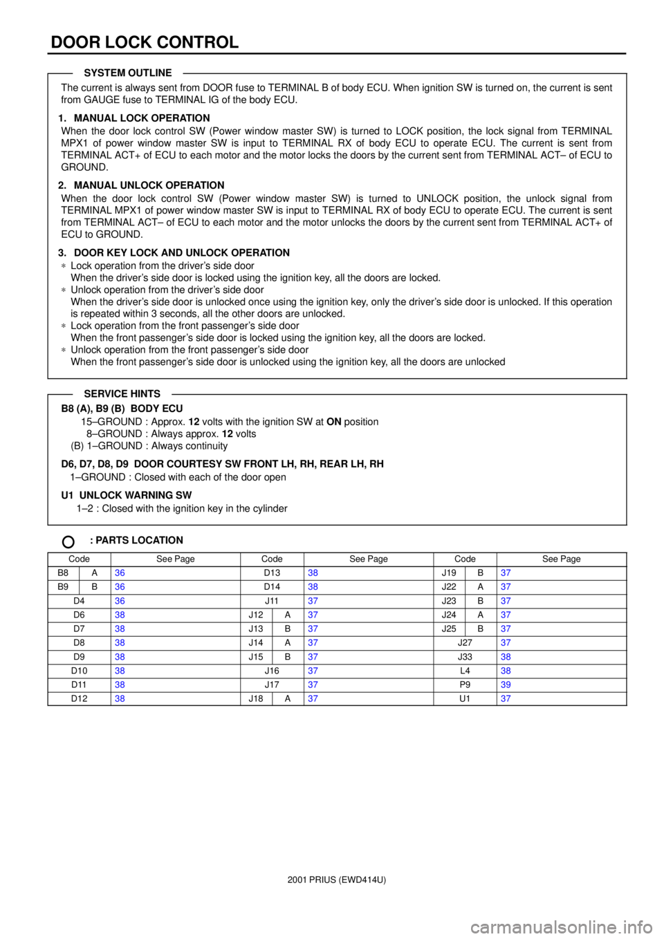
The current is always sent from DOOR fuse to TERMINAL B of body ECU. When ignition SW is turned on, the current is sent
from GAUGE fuse to TERMINAL IG of the body ECU.
1. MANUAL LOCK OPERATION
When the door lock control SW (Power window master SW) is turned to LOCK position, the lock signal from TERMINAL
MPX1 of power window master SW is input to TERMINAL RX of body ECU to operate ECU. The current is sent from
TERMINAL ACT+ of ECU to each motor and the motor locks the doors by the current sent from TERMINAL ACT± of ECU to
GROUND.
2. MANUAL UNLOCK OPERATION
When the door lock control SW (Power window master SW) is turned to UNLOCK position, the unlock signal from
TERMINAL MPX1 of power window master SW is input to TERMINAL RX of body ECU to operate ECU. The current is sent
from TERMINAL ACT± of ECU to each motor and the motor unlocks the doors by the current sent from TERMINAL ACT+ of
ECU to GROUND.
3. DOOR KEY LOCK AND UNLOCK OPERATION
*Lock operation from the driver's side door
When the driver's side door is locked using the ignition key, all the doors are locked.
*Unlock operation from the driver's side door
When the driver's side door is unlocked once using the ignition key, only the driver's side door is unlocked. If this operation
is repeated within 3 seconds, all the other doors are unlocked.
*Lock operation from the front passenger's side door
When the front passenger's side door is locked using the ignition key, all the doors are locked.
*Unlock operation from the front passenger's side door
When the front passenger's side door is unlocked using the ignition key, all the doors are unlocked
B8 (A), B9 (B) BODY ECU
15±GROUND : Approx. 12 volts with the ignition SW at ON position
8±GROUND : Always approx. 12 volts
(B) 1±GROUND : Always continuity
D6, D7, D8, D9 DOOR COURTESY SW FRONT LH, RH, REAR LH, RH
1±GROUND : Closed with each of the door open
U1 UNLOCK WARNING SW
1±2 : Closed with the ignition key in the cylinder
: PARTS LOCATION
CodeSee PageCodeSee PageCodeSee Page
B8A36D1338J19B37
B9B36D1438J22A37
D436J1137J23B37
D638J12A37J24A37
D738J13B37J25B37
D838J14A37J2737
D938J15B37J3338
D1038J1637L438
D1138J1737P939
D1238J18A37U137
SYSTEM OUTLINE
SERVICE HINTS
Page 142 of 1943
2001 PRIUS (EWD414U)
WIRELESS DOOR LOCK CONTROL
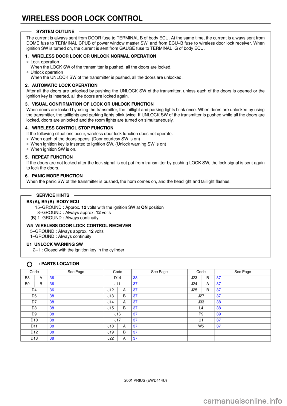
The current is always sent from DOOR fuse to TERMINAL B of body ECU. At the same time, the current is always sent from
DOME fuse to TERMINAL CPUB of power window master SW, and from ECU±B fuse to wireless door lock receiver. When
ignition SW is turned on, the current is sent from GAUGE fuse to TERMINAL IG of body ECU.
1. WIRELESS DOOR LOCK OR UNLOCK NORMAL OPERATION
*Lock operation
When the LOCK SW of the transmitter is pushed, all the doors are locked.
*Unlock operation
When the UNLOCK SW of the transmitter is pushed, all the doors are unlocked.
2. AUTOMATIC LOCK OPERATION
After all the doors are unlocked by pushing the UNLOCK SW of the transmitter, unless each of the doors is opened or the
ignition key is inserted, all the doors are locked again.
3. VISUAL CONFIRMATION OF LOCK OR UNLOCK FUNCTION
When doors are locked by using the transmitter, the taillight and parking lights blink once. When doors are unlocked by using
the transmitter, the taillights and parking lights blink twice. If UNLOCK SW of the transmitter is pushed while all the doors are
locked, doors are unlocked and the room lights are turned on simultaneously.
4. WIRELESS CONTROL STOP FUNCTION
If the following situations occur, wireless door lock function does not operate.
*When each of the doors opens. (Door courtesy SW is on)
*When ignition key is inserted to ignition SW. (Unlock warning SW is on)
*When ignition SW is on.
5. REPEAT FUNCTION
If the doors are not locked after the lock signal is out put from transmitter by pushing LOCK SW, the lock signal is sent again
to lock the doors.
6. PANIC MODE FUNCTION
When the panic SW of the transmitter is pushed, the horn comes on, and the headlight and taillight flashes.
B8 (A), B9 (B) BODY ECU
15±GROUND : Approx. 12 volts with the ignition SW at ON position
8±GROUND : Always approx. 12 volts
(B) 1±GROUND : Always continuity
W5 WIRELESS DOOR LOCK CONTROL RECEIVER
5±GROUND : Always approx. 12 volts
1±GROUND : Always continuity
U1 UNLOCK WARNING SW
2±1 : Closed with the ignition key in the cylinder
: PARTS LOCATION
CodeSee PageCodeSee PageCodeSee Page
B8A36D1438J23B37
B9B36J1137J24A37
D436J12A37J25B37
D638J13B37J2737
D738J14A37J3338
D838J15B37L438
D938J1637P939
D1038J1737U137
D1138J18A37W537
D1238J19B37
D1338J22A37
SYSTEM OUTLINE
SERVICE HINTS
Page 168 of 1943
2001 PRIUS (EWD414U)
SRS
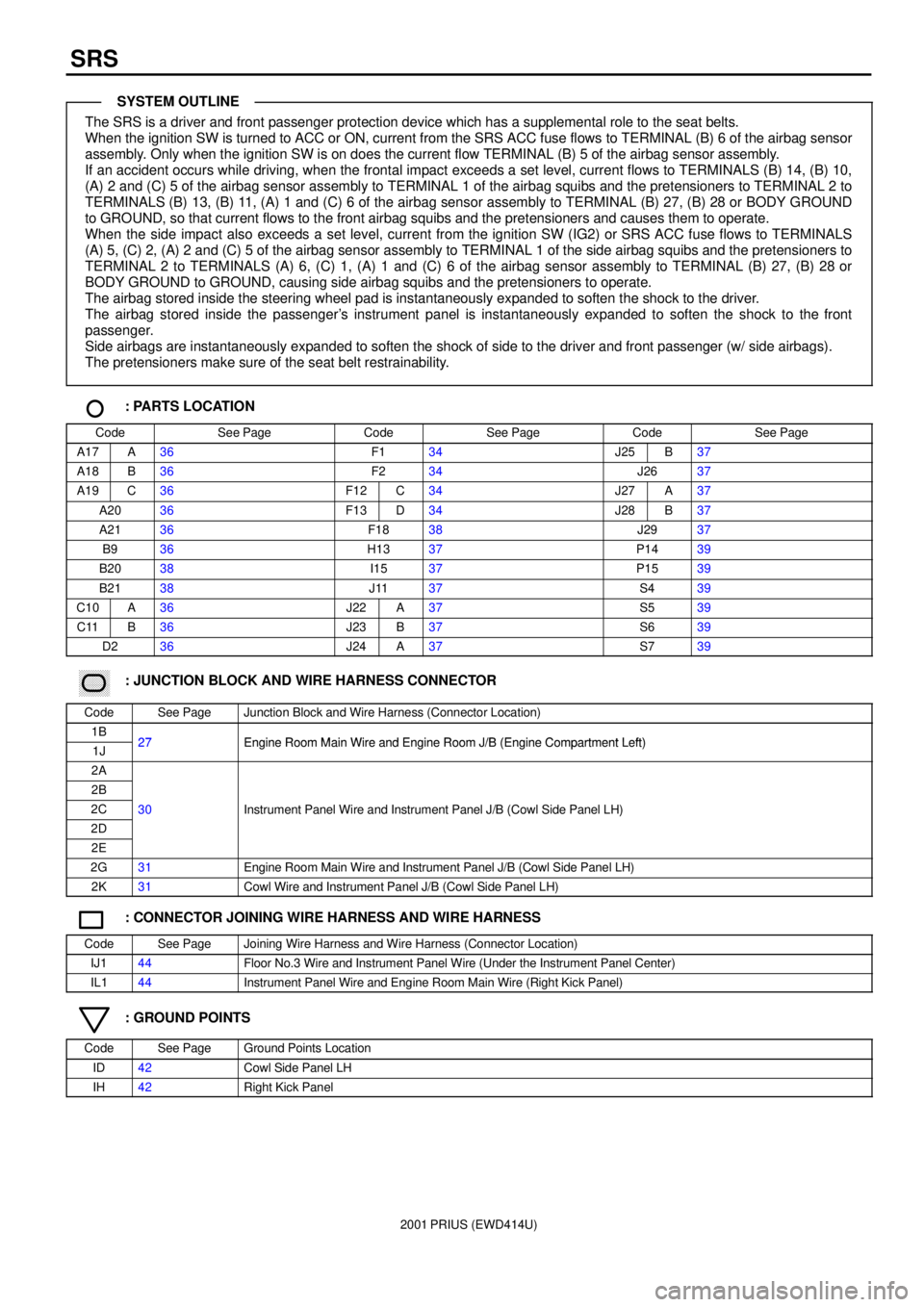
The SRS is a driver and front passenger protection device which has a supplemental role to the seat belts.
When the ignition SW is turned to ACC or ON, current from the SRS ACC fuse flows to TERMINAL (B) 6 of the airbag sensor
assembly. Only when the ignition SW is on does the current flow TERMINAL (B) 5 of the airbag sensor assembly.
If an accident occurs while driving, when the frontal impact exceeds a set level, current flows to TERMINALS (B) 14, (B) 10,
(A) 2 and (C) 5 of the airbag sensor assembly to TERMINAL 1 of the airbag squibs and the pretensioners to TERMINAL 2 to
TERMINALS (B) 13, (B) 11, (A) 1 and (C) 6 of the airbag sensor assembly to TERMINAL (B) 27, (B) 28 or BODY GROUND
to GROUND, so that current flows to the front airbag squibs and the pretensioners and causes them to operate.
When the side impact also exceeds a set level, current from the ignition SW (IG2) or SRS ACC fuse flows to TERMINALS
(A) 5, (C) 2, (A) 2 and (C) 5 of the airbag sensor assembly to TERMINAL 1 of the side airbag squibs and the pretensioners to
TERMINAL 2 to TERMINALS (A) 6, (C) 1, (A) 1 and (C) 6 of the airbag sensor assembly to TERMINAL (B) 27, (B) 28 or
BODY GROUND to GROUND, causing side airbag squibs and the pretensioners to operate.
The airbag stored inside the steering wheel pad is instantaneously expanded to soften the shock to the driver.
The airbag stored inside the passenger's instrument panel is instantaneously expanded to soften the shock to the front
passenger.
Side airbags are instantaneously expanded to soften the shock of side to the driver and front passenger (w/ side airbags).
The pretensioners make sure of the seat belt restrainability.
: PARTS LOCATION
CodeSee PageCodeSee PageCodeSee Page
A17A36F134J25B37
A18B36F234J2637
A19C36F12C34J27A37
A2036F13D34J28B37
A2136F1838J2937
B936H1337P1439
B2038I1537P1539
B2138J1137S439
C10A36J22A37S539
C11B36J23B37S639
D236J24A37S739
������ ���: JUNCTION BLOCK AND WIRE HARNESS CONNECTOR
CodeSee PageJunction Block and Wire Harness (Connector Location)
1B27Engine Room Main Wire and Engine Room J/B (Engine Compartment Left)1J27Engine Room Main Wire and Engine Room J/B (Engine Compartment Left)
2A
2B
2C30Instrument Panel Wire and Instrument Panel J/B (Cowl Side Panel LH)
2D
()
2E
2G31Engine Room Main Wire and Instrument Panel J/B (Cowl Side Panel LH)
2K31Cowl Wire and Instrument Panel J/B (Cowl Side Panel LH)
: CONNECTOR JOINING WIRE HARNESS AND WIRE HARNESS
CodeSee PageJoining Wire Harness and Wire Harness (Connector Location)
IJ144Floor No.3 Wire and Instrument Panel Wire (Under the Instrument Panel Center)
IL144Instrument Panel Wire and Engine Room Main Wire (Right Kick Panel)
: GROUND POINTS
CodeSee PageGround Points Location
ID42Cowl Side Panel LH
IH42Right Kick Panel
SYSTEM OUTLINE
Page 202 of 1943
2001 PRIUS (EWD414U)
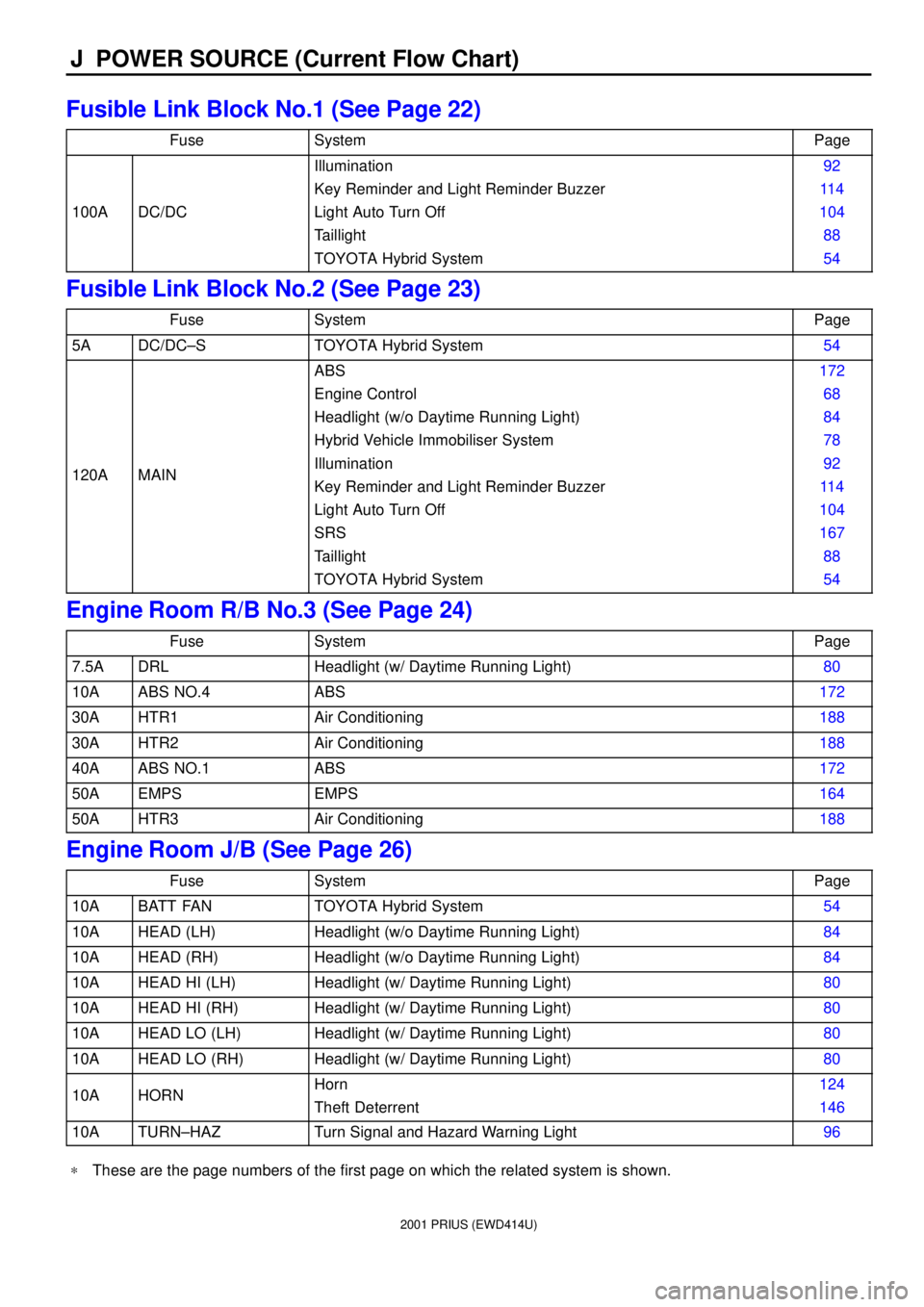
J POWER SOURCE (Current Flow Chart)
Fusible Link Block No.1 (See Page 22)
FuseSystemPage
100ADC/DC
Illumination
Key Reminder and Light Reminder Buzzer
Light Auto Turn Off
Taillight
TOYOTA Hybrid System92
11 4
104
88
54
Fusible Link Block No.2 (See Page 23)
FuseSystemPage
5ADC/DC±STOYOTA Hybrid System54
120AMAIN
ABS
Engine Control
Headlight (w/o Daytime Running Light)
Hybrid Vehicle Immobiliser System
Illumination
Key Reminder and Light Reminder Buzzer
Light Auto Turn Off
SRS
Taillight
TOYOTA Hybrid System172
68
84
78
92
11 4
104
167
88
54
Engine Room R/B No.3 (See Page 24)
FuseSystemPage
7.5ADRLHeadlight (w/ Daytime Running Light)80
10AABS NO.4ABS172
30AHTR1Air Conditioning188
30AHTR2Air Conditioning188
40AABS NO.1ABS172
50AEMPSEMPS164
50AHTR3Air Conditioning188
Engine Room J/B (See Page 26)
FuseSystemPage
10ABATT FANTOYOTA Hybrid System54
10AHEAD (LH)Headlight (w/o Daytime Running Light)84
10AHEAD (RH)Headlight (w/o Daytime Running Light)84
10AHEAD HI (LH)Headlight (w/ Daytime Running Light)80
10AHEAD HI (RH)Headlight (w/ Daytime Running Light)80
10AHEAD LO (LH)Headlight (w/ Daytime Running Light)80
10AHEAD LO (RH)Headlight (w/ Daytime Running Light)80
10AHORNHorn
Theft Deterrent124
146
10ATURN±HAZTurn Signal and Hazard Warning Light96
*These are the page numbers of the first page on which the related system is shown.
Page 203 of 1943
2001 PRIUS (EWD414U)
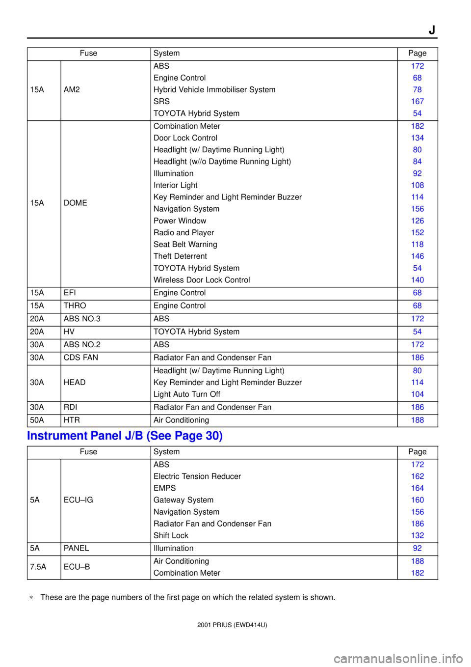
J
FuseSystemPage
15AAM2
ABS
Engine Control
Hybrid Vehicle Immobiliser System
SRS
TOYOTA Hybrid System172
68
78
167
54
15ADOME
Combination Meter
Door Lock Control
Headlight (w/ Daytime Running Light)
Headlight (w//o Daytime Running Light)
Illumination
Interior Light
Key Reminder and Light Reminder Buzzer
Navigation System
Power Window
Radio and Player
Seat Belt Warning
Theft Deterrent
TOYOTA Hybrid System
Wireless Door Lock Control182
134
80
84
92
108
11 4
156
126
152
11 8
146
54
140
15AEFIEngine Control68
15ATHROEngine Control68
20AABS NO.3ABS172
20AHVTOYOTA Hybrid System54
30AABS NO.2ABS172
30ACDS FANRadiator Fan and Condenser Fan186
30AHEAD
Headlight (w/ Daytime Running Light)
Key Reminder and Light Reminder Buzzer
Light Auto Turn Off80
11 4
104
30ARDIRadiator Fan and Condenser Fan186
50AHTRAir Conditioning188
Instrument Panel J/B (See Page 30)
FuseSystemPage
5AECU±IG
ABS
Electric Tension Reducer
EMPS
Gateway System
Navigation System
Radiator Fan and Condenser Fan
Shift Lock172
162
164
160
156
186
132
5APANELIllumination92
7.5AECU±BAir Conditioning
Combination Meter188
182
*These are the page numbers of the first page on which the related system is shown.
Page 204 of 1943

2001 PRIUS (EWD414U)
J POWER SOURCE (Current Flow Chart)
FuseSystemPage
7.5AECU±B
Door Lock Control
EMPS
Gateway System
Headlight (w/ Daytime Running Light)
Hybrid Vehicle Immobiliser System
Interior Light
Key Reminder and Light Reminder Buzzer
Light Auto Turn Off
Power Window
Theft Deterrent
Wireless Door Lock Control134
164
160
80
78
108
11 4
104
126
146
140
7.5AOBDIIEngine Control
Theft Deterrent68
146
7.5ATAIL
Key Reminder and Light Reminder Buzzer
Light Auto Turn Off
Taillight11 4
104
88
10AACC
Combination Meter
Gateway System
Navigation System
Radio and Player
Remote Control Mirror
Shift Lock
SRS182
160
156
152
130
132
167
10AGAUGE
ABS
Air Conditioning
Back±Up Light
Combination Meter
Door Lock Control
EMPS
Engine Control
Headlight (w/ Daytime Running Light)
Key Reminder and Light Reminder Buzzer
Light Auto Turn Off
Navigation System
Power Window
Rear Window Defogger
Seat Belt Warning
Theft Deterrent
TOYOTA Hybrid System
Turn Signal and Hazard Warning Light
Wireless Door Lock Control172
188
102
182
134
164
68
80
11 4
104
156
126
180
11 8
146
54
96
140
10AHTRAir Conditioning188
10ASRS ACCSRS167
*These are the page numbers of the first page on which the related system is shown.
Page 205 of 1943

2001 PRIUS (EWD414U)
J
FuseSystemPage
15ACIGCigarette Lighter122
15ASTOP
ABS
Engine Control
Shift Lock
Stop Light172
68
132
100
15AWASHERWiper and Washer120
20APWR1Power Window126
30ADOOR
Door Lock Control
Theft Deterrent
Wireless Door Lock Control134
146
140
30APOWERPower Window126
30AWIPERWiper and Washer120
40ADEFRear Window Defogger180
*These are the page numbers of the first page on which the related system is shown.