Page 1233 of 1943
± DIAGNOSTICSBODY CONTROL SYSTEM
DI±693
2001 PRIUS (RM778U)
INSPECTION PROCEDURE
1 Check AM1 fuse.
CHECK:
Check continuity of AM1 fuse.
OK:
Continuity
NG Replace the failure fuse.
OK
2 Check voltage between terminals 8, 15 and E of body ECU connector.
PREPARATION:
Turn ignition switch ON.
CHECK:
Measure voltage between terminals 8, 15 and E.
OK:
Voltage: 10 ± 14V
OK Proceed to next circuit inspection shown on
problem symptoms table (See page DI±683).
NG
3 Check wireharness and connector between body ECU and body ground (See
page IN±41).
NG Repair or replace wireharness or connector.
OK
Check and repair wireharness and connector
between body ECU and battery.
Page 1245 of 1943
I11582
(±) (+)
1
I11583
(±)
1 (+)
± DIAGNOSTICSBODY CONTROL SYSTEM
DI±705
2001 PRIUS (RM778U)
INSPECTION PROCEDURE
HINT:
The flow chart below is based on the premise that the horns blow normally whenever the horn switch is oper-
ated. If horn operation is not normal when the horn switch is operated, check the horn switch.
1 Check voltage between terminal 1 of theft deterrent horn connector and body
ground.
PREPARATION:
Remove the theft deterrent horn and disconnect the connector.
CHECK:
Measure voltage between terminal 1 of theft deterrent horn
connector and body ground.
OK:
Voltage: 10 ± 14 V
NG Check and repair harness and connector be-
tween HORN fuse and theft deterrent horn.
OK
2 Check theft deterrent horn.
CHECK:
Connect positive (+) lead to terminal 1 and negative (±) lead to
ground to theft deterrent horn connector.
OK:
Theft deterrent horn blows.
NG Replace theft deterrent horn.
OK
Page 1276 of 1943
± DIAGNOSTICSDRIVER DOOR CONTROL SYSTEM
DI±741
2001 PRIUS (RM778U)
INSPECTION PROCEDURE
1 Check PWR1, AM1 and DOME fuse.
CHECK:
Check continuity of PWR1, AM1 and DOME fuse.
OK:
Continuity
NG Replace the failure fuse.
OK
2 Check voltage between terminals B, CPUB, IG and GND of driver door ECU con-
nector.
PREPARATION:
Turn ignition switch ON.
CHECK:
Measure voltage between terminals IG, and GND.
OK:
Voltage: 10 ± 14V
PREPARATION:
(a) Turn ignition switch OFF.
(b) Disconnect the driver door ECU connector.
CHECK:
Measure voltage between terminals B, CPUB and GND.
OK:
Voltage: 10 ± 14V
OK Proceed to next circuit inspection shown on
problem symptoms table (See page DI±734).
NG
Page 1322 of 1943
± DIAGNOSTICSMULTIPLEX COMMUNICATION SYSTEM
DI±793
2001 PRIUS (RM778U)
INSPECTION PROCEDURE
1 Check ECU±B and ECU±IG fuse.
CHECK:
Check continuity of ECU±B and ECU±IG fuse.
OK:
Continuity
NG Replace the failure fuse.
OK
2 Check voltage between terminals BATT, IG and GND of body ECU connector.
PREPARATION:
(a) Turn ignition switch OFF.
(b) Disconnect the gateway ECU connector.
CHECK:
Measure voltage between terminals BATT and GND.
OK:
Voltage: 10 ± 14 V
OK Check and repair wireharness and connector
between gateway ECU and battery.
NG
3 Check wireharness and connector between gateway ECU and body ground (See
page IN±41).
NG Repair or replace wireharness or connector.
OK
Check and repair wireharness and connector
between gateway ECU and battery.
Page 1348 of 1943

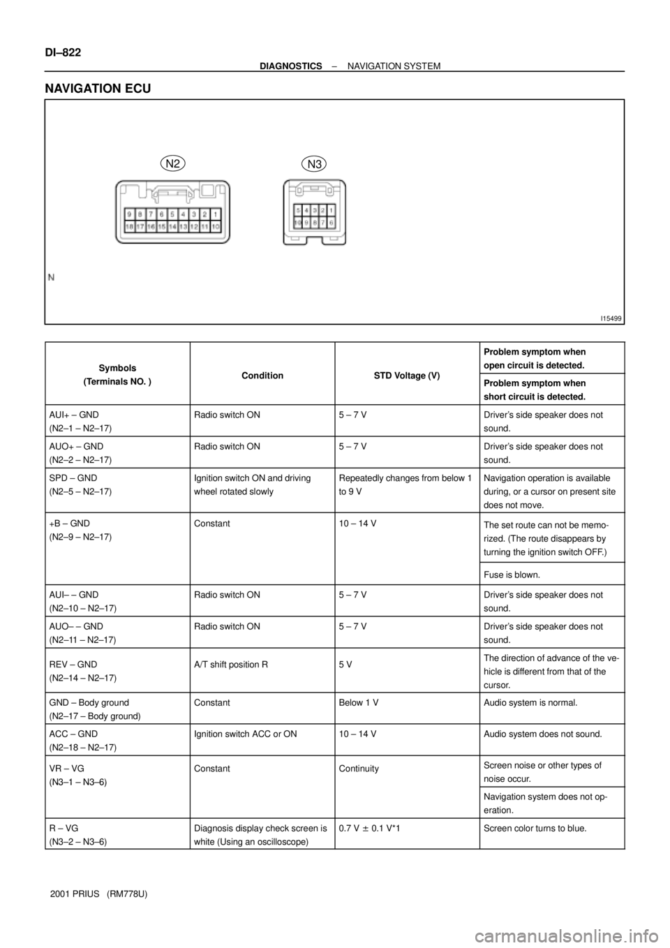
I15499
N2
N3
DI±822
± DIAGNOSTICSNAVIGATION SYSTEM
2001 PRIUS (RM778U)
NAVIGATION ECU
SymbolsC ditiSTD V lt (V)
Problem symptom when
open circuit is detected.
Symbols
(Terminals NO. )ConditionSTD Voltage (V)Problem symptom when
short circuit is detected.
AUI+ ± GND
(N2±1 ± N2±17)Radio switch ON5 ± 7 VDriver's side speaker does not
sound.
AUO+ ± GND
(N2±2 ± N2±17)Radio switch ON5 ± 7 VDriver's side speaker does not
sound.
SPD ± GND
(N2±5 ± N2±17)Ignition switch ON and driving
wheel rotated slowlyRepeatedly changes from below 1
to 9 VNavigation operation is available
during, or a cursor on present site
does not move.
+B ± GND
(N2±9 ± N2±17)Constant10 ± 14 VThe set route can not be memo-
rized. (The route disappears by
turning the ignition switch OFF.)
Fuse is blown.
AUI± ± GND
(N2±10 ± N2±17)Radio switch ON5 ± 7 VDriver's side speaker does not
sound.
AUO± ± GND
(N2±11 ± N2±17)Radio switch ON5 ± 7 VDriver's side speaker does not
sound.
REV ± GND
(N2±14 ± N2±17)A/T shift position R5 VThe direction of advance of the ve-
hicle is different from that of the
cursor.
GND ± Body ground
(N2±17 ± Body ground)ConstantBelow 1 VAudio system is normal.
ACC ± GND
(N2±18 ± N2±17)Ignition switch ACC or ON10 ± 14 VAudio system does not sound.
VR ± VG
(N3±1 ± N3±6)
ConstantContinuityScreen noise or other types of
noise occur.
(N3±1 ± N3±6)
Navigation system does not op-
eration.
R ± VG
(N3±2 ± N3±6)Diagnosis display check screen is
white (Using an oscilloscope)0.7 V ± 0.1 V*1Screen color turns to blue.
Page 1349 of 1943

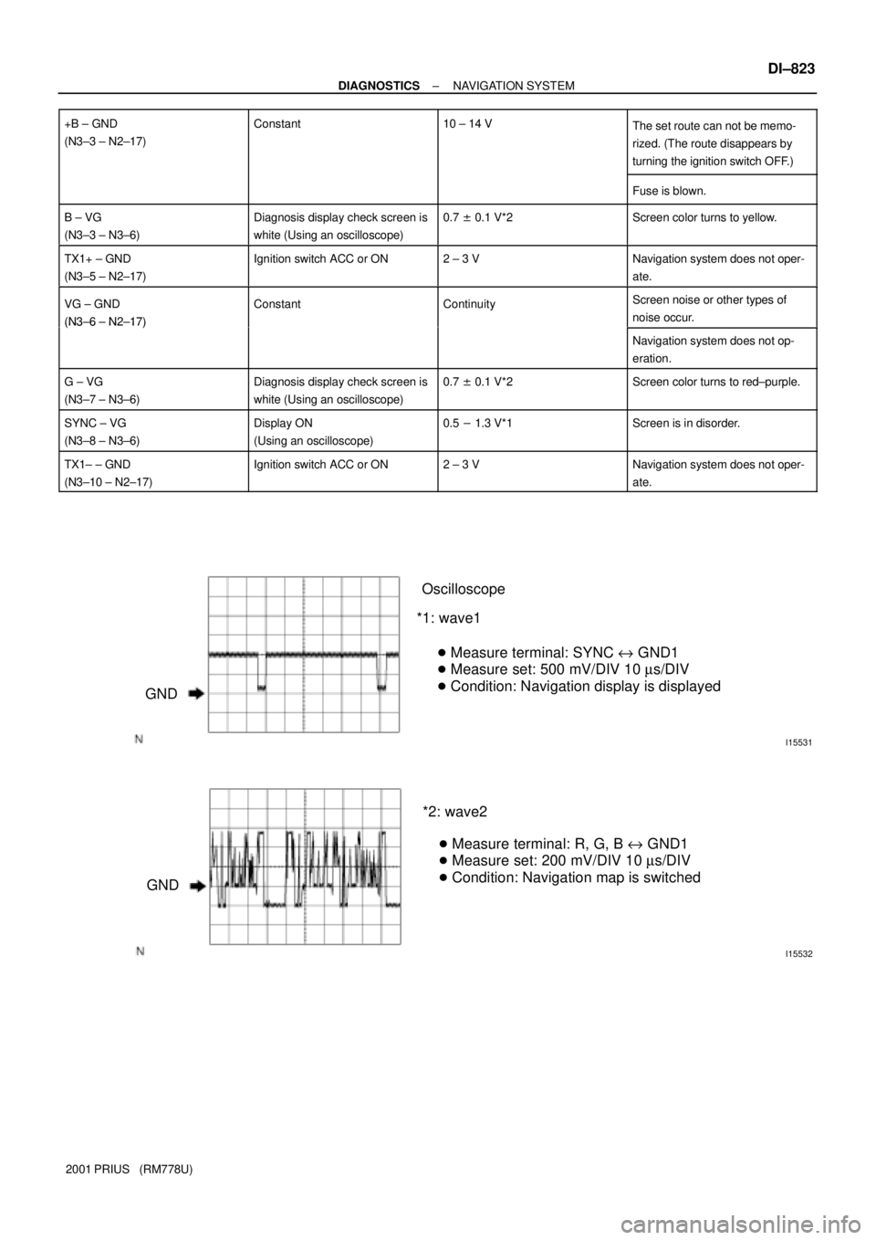
I15531
GNDOscilloscope
*1: wave1
� Measure terminal: SYNC e GND1
� Measure set: 500 mV/DIV 10 ms/DIV
� Condition: Navigation display is displayed
I15532
GND*2: wave2
� Measure terminal: R, G, B e GND1
� Measure set: 200 mV/DIV 10 ms/DIV
� Condition: Navigation map is switched
± DIAGNOSTICSNAVIGATION SYSTEM
DI±823
2001 PRIUS (RM778U) +B ± GND
(N3±3 ± N2±17)
Constant10 ± 14 VThe set route can not be memo-
rized. (The route disappears by
turning the ignition switch OFF.)
Fuse is blown.
B ± VG
(N3±3 ± N3±6)Diagnosis display check screen is
white (Using an oscilloscope)0.7 ± 0.1 V*2Screen color turns to yellow.
TX1+ ± GND
(N3±5 ± N2±17)Ignition switch ACC or ON2 ± 3 VNavigation system does not oper-
ate.
VG ± GND
(N3±6 ± N2±17)
ConstantContinuityScreen noise or other types of
noise occur.
(N3±6 ± N2±17)
Navigation system does not op-
eration.
G ± VG
(N3±7 ± N3±6)Diagnosis display check screen is
white (Using an oscilloscope)0.7 ± 0.1 V*2Screen color turns to red±purple.
SYNC ± VG
(N3±8 ± N3±6)Display ON
(Using an oscilloscope)0.5 - 1.3 V*1Screen is in disorder.
TX1± ± GND
(N3±10 ± N2±17)Ignition switch ACC or ON2 ± 3 VNavigation system does not oper-
ate.
Page 1430 of 1943
I18410
Instrument Panel J/B
HTR Fuse
± DIAGNOSTICSAIR CONDITIONING SYSTEM
DI±923
2001 PRIUS (RM778U)
3 Check HTR fuse.
PREPARATION:
Remove HTR fuse from instrument panel J/B.
CHECK:
Check continuity of HTR fuse.
OK:
Continuity exists.
NG Check for shot in all the harness and compo-
nents connected to the HTR fuse.
OK
Check and repair harness and connector between A/C amplifier and battery.
Page 1432 of 1943
I18172
+B
(+) (±)
I18410
ECU±B Fuse Instrument Panel J/B
± DIAGNOSTICSAIR CONDITIONING SYSTEM
DI±925
2001 PRIUS (RM778U)
INSPECTION PROCEDURE
1 Check voltage between terminal +B of A/C amplifier connector and body ground.
PREPARATION:
Remove A/C amplifier with connectors still connected.
CHECK:
Measure voltage between terminal +B of A/C amplifier connec-
tor and body ground.
OK:
Voltage : 10 ± 14 V
OK Proceed to next circuit inspection shown on
problem symptoms table (See page DI±874).
NG
2 Check ECU±B fuse.
PREPARATION:
Remove ECU±B fuse from instrument panel J/B.
CHECK:
Check continuity of ECU±B fuse.
OK:
Continuity exists.
NG Check for short in all the harness and compo-
nents connected to the ECU±B fuse (See page
IN±41).
OK
Check and repair harness and connector between A/C amplifier and battery.