Page 1767 of 1943
 Even when the system is not set
(Headlights stay on).
Headlight control relay circuitDI±697
Even when the system is")
BE±10
± BODY ELECTRICALTROUBLESHOOTING
1677 Author�: Date�:
2001 PRIUS (RM778U) Even when the system is not set
(Headlights stay on).
Headlight control relay circuitDI±697
Even when the system is not set
(Taillights stay on).Taillight control relay circuitDI±691
WIRELESS DOOR LOCK CONTROL SYSTEM
This system uses the multiplex communication system, so check diagnosis system of the multiplex commu-
nication system before you proceed with troubleshooting.
HINT:
�Troubleshooting of the wireless door lock control system is based on the premise that the door lock
control system is operating normally. Accordingly, before troubleshooting the wireless door lock control
system, first make certain that the door lock control system is operating normally.
�If the trouble still reappears even though there are no abnormalities in any of the other circuits, then
check and replace the Wireless Door Lock Control Receiver as the last step.
SymptomSuspect AreaSee page
All functions of wireless door lock control system do not operate.
1. Transmitter
2. Wireless Door Lock Control Receiver
3. Wire Harness
4. Body ECUBE±83
BE±83
±
DI±678
POWER MIRROR CONTROL SYSTEM
SymptomSuspect AreaSee page
Both right and left mirrors do not operate.
1. ACC Fuse
2. ACC Relay
3. Mirror Switch
4. Wire HarnessBE±12
BE±12
BE±93
±
Only one side of mirror does not operate.1. Mirror Motor
2. Wire HarnessBE±93
±
AUDIO SYSTEM
SymptomSuspect AreaSee page
Audio system abnormal operation.TROUBLESHOOTINGBE±97
CLOCK SYSTEM
SymptomSuspect AreaSee page
Clock will not operate.TROUBLESHOOTING NO.1BE±102
Clock loses or gains time.TROUBLESHOOTING NO.2BE±102
HYBRID BEHICLE IMMOBILIZER SYSTEM
SymptomSuspect AreaSee page
Hybrid vehicle immobilizer system does not operate.Pre±checkBE±111
Page 1768 of 1943
± BODY ELECTRICALTROUBLESHOOTING
BE±11
1678 Author�: Date�:
2001 PRIUS (RM778U)
HORN SYSTEM
SymptomSuspect AreaSee page
Horn system does not operate.
1. HORN Fuse
2. Horn Relay
3. Horn Switch
4. Horn
5. Wire HarnessBE±12
BE±117
BE±117
BE±117
±
Horns blow all the time.
1. Horn Relay
2. Horn Switch
3. Wire HarnessBE±117
BE±117
±
One horn operates but the other horn does not operate.1. Horn
2. Wire HarnessBE±117
±
Horns operate abnormally.
1. Horn Relay
2. Horn
3. Wire HarnessBE±117
BE±117
±
Page 1770 of 1943
I17787
Engine room J/B:
Fuses:
1. HTR Fuse
2. RDI Fuse
3. ABS No. 2 Fuse
4. CDS FAN Fuse
5. HORN Fuse
6. THRO Fuse
7. ABS No. 3 Fuse
8. TURN±HAZ Fuse
9. AM2 Fuse
10. BATT FANRelays:
A. FAN NO. 1 Relay
B. FAN NO. 2 Relay
C. FAN NO. 3 Relay
D. IG2 Relay
E. HORN Relay
F. HTR Relay
G. EFI Relay
H. CLR MG Relay
I. HEAD Relay
J. CIR OPN Relay
K. DIM Relay *1
123 4 5 6 7 8
91011
121314
1516
17
18 K
J
A B
C D E
F
G H
I
11. DOME Fuse
12. HEAD HI (RH) Fuse *1
13. HEAD HI (LH) Fuse *1
14. HEAD LO (LH) *1
HEAD (LH) *2
15. HEAD LO (RH) *1
HEAD (RH) *2
16. EFI Fuse
17. HEV Fuse
18. HEAD Fuse *1
*1: w/ Daytime Running Light
*2: w/o Daytime Running Light
± BODY ELECTRICALPOWER SOURCE
BE±13
1680 Author�: Date�:
2001 PRIUS (RM778U)
Page 1771 of 1943
I17788
Instrument Panel J/B:
Fuses: Relays:
A. IG1 Relay
B. ACC Relay
C. TAIL Relay
D. POWER Relay
E. DEF Relay
1
2
3
4
5
6
7
8
9
10
11
12
13
14
15 A
B C
D
16
E
1. HTR Fuse
2. STOP Fuse
3. ECU±B Fuse
4. DOOR Fuse
5. OBDII Fuse
6. PWR1 Fuse
7. AM1 Fuse8. GAUGE Fuse
9. ECU±IG Fuse
10. WIPER Fuse
11. WASHER Fuse
12. PANEL Fuse
13. TAIL Fuse
14. ACC Fuse15. CIG Fuse
16. SRS ACC Fuse
17. PWR Fuse
18 DEF Fuse
1718 BE±14
± BODY ELECTRICALPOWER SOURCE
1681 Author�: Date�:
2001 PRIUS (RM778U)
Page 1772 of 1943
I17789
1 2 3456
7 A B
C
D E
Fuses: Relays: Engine Room R/B No. 3:
G H
1. HTR2 Fuse
2. HTR1 Fuse
3. ABS No. 4 Fuse
4. ABS No. 1 Fuse5. EMPS Fuse
6. HTR3 Fuse
7. DRL FuseA. A/C W/P Relay
B. ABS SOL Relay
C. DRL Relay
D. HTR2 RelayE. HTR1 Relay
G. HTR3 Relay
H. EPMS Relay
Engine Room R/B No. 2:
A B C
Relays:
A. IGCT Relay
B. HYDRO MTR No. 2 Relay
C. HYDRO MTR No. 1 Relay
± BODY ELECTRICALPOWER SOURCE
BE±15
1682 Author�: Date�:
2001 PRIUS (RM778U)
Page 1782 of 1943
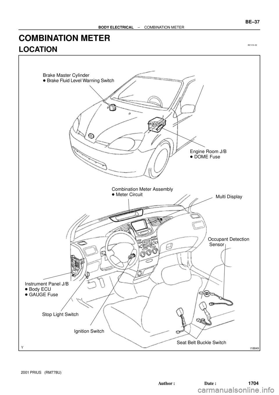
BE1VS±02
I18849
Brake Master Cylinder
� Brake Fluid Level Warning Switch
Combination Meter Assembly
� Meter Circuit
Multi Display
Ignition Switch
Instrument Panel J/B
� Body ECU
� GAUGE Fuse
Stop Light Switch
Engine Room J/B
� DOME Fuse
Seat Belt Buckle Switch
Occupant Detection
Sensor
± BODY ELECTRICALCOMBINATION METER
BE±37
1704 Author�: Date�:
2001 PRIUS (RM778U)
COMBINATION METER
LOCATION
Page 1786 of 1943
No. Wiring connector side
1
2
3
10
11
12
13
14
15
16
17
18
19
20
21
22EMPS ECU
Fuel tank temperature (+)
Hybrid vehicle control ECU (4P)
Ground
Ground
Center airbag sensor assembly
Headlight dimmer switch
Turn signal switch (Right)
Turn signal switch (Left)
Fuel tank temperature (±)
DOME Fuse
GAUGE FuseODO/TRIP switch (TC)
ODO/TRIP switch (E)
ODO/TRIP switch (ODO)
9 ABS ECU (SI)
ABS ECU (ABS)
2
3
4
5
6
7 1 Back±up light relay
Body ECU
Engine ECM
ACC Fuse
Light control rheostat (TC)
Light control rheostat (TR) A
BBody ECU
± BODY ELECTRICALCOMBINATION METER
BE±41
2001 PRIUS (RM778U)
Page 1819 of 1943
BE±82
± BODY ELECTRICALWIRELESS DOOR LOCK CONTROL SYSTEM
2001 PRIUS (RM778U)
DOME fuse or wire harness faulty.
Ye s
+B power source check:
Check that there is constantly 10 to 14 V voltage at the
connector terminal 5 (+B) of wireless door control
receiver.
No
Wire harness faulty.
Body ground open and contact error.
Ye s
Body ground check:
Check that continuity exists between the connector
terminal 1 (GND) of the wireless door control receiver
and body ground.
No
Wireless door control receiver faulty.


Hybrid vehicle control ECU (4P)
Ground
Ground
Center airbag sensor assembly
Headlight dimmer sw")

DOME fuse or wire harness faulty.
Ye s
+B power source check:
Check that there is constantly 10 to 14 V voltage at the")