Page 1095 of 2572
- DIAGNOSTICSENGINE IMMOBILIZER SYSTEM
05-2005
2195 Author�: Date�:
2005 HIGHLANDER REPAIR MANUAL (RM1144U)
DTC B2795 UNMATCHED KEY CODE
CIRCUIT DESCRIPTION
This DTC is output when a key with a key code that has not been registered in the ECU is inserted into the
ignition key cylinder.
DTC No.DTC Detection ConditionTrouble Area
B2795Key with unregistered key code is inserted�Key
INSPECTION PROCEDURE
1 DELETE DTC AND INSERT ALL PRESENTLY AVAILABLE KEYS TO CHECK
WHETHER ENGINE STARTS OR NOT
OK NO PROBLEM
(BECAUSE OF KEY RE-REGISTRATION)
NG
REPLACE KEY THAT DOES NOT START ENGINE
052IJ-12
Page 1097 of 2572

INSPECTION PROCEDURE
HINT:
Start the inspection from step 1 when using the hand-held teste")
- DIAGNOSTICSENGINE IMMOBILIZER SYSTEM
05-2007
2197 Author�: Date�:
2005 HIGHLANDER REPAIR MANUAL (RM1144U)
INSPECTION PROCEDURE
HINT:
Start the inspection from step 1 when using the hand-held tester and start from step 2 when not using the
hand-held tester.
1 READ VALUE OF HAND-HELD TESTER
(IMMOBILISER ECU (TRANSPONDER KEY ECU ASSY) (SWITCH CONDITION))
(a) Connect the hand-held tester to the DLC3.
(b) Turn the ignition switch ON with the key that does not start the engine.
(c) Select the item ºIMMOBILIZERº on the hand-held tester.
OK: ºSETº (Ignition switch ON) appears on the screen.
ItemMeasurement Item/
Display (Range)Normal ConditionDiagnostic Note
IMMOBILIZERImmobilizer system status
/SET or UNSETUNSET: Without key
SET: Ignition switch ON-
OK NORMAL
NG
2 CHECK WHETHER ENGINE STARTS WITH OTHER KEYS
(a) Check whether the engine starts with the other keys for the vehicle.
OK RE-REGISTER OR REPLACE KEY THAT WILL
NOT START ENGINE
NG
HINT:
Start the inspection from step 3 when using the hand-held tester and start from step 4 when not using the
hand-held tester.
3 READ VALUE OF HAND-HELD TESTER
(IMMOBILIZER ECU (TRANSPONDER KEY ECU ASSY) (SWITCH CONDITION))
(a) Connect the hand-held tester to the DLC3.
(b) Turn the ignition switch ON with the key that does not start the engine.
(c) On the hand-held tester, select the following menu item: DIAGNOSIS/ENHANCED OBD II/DATA
LIST/IMMOBILIZER/ANTENNA COIL. Read the values.
OK: ºNORMALº (Antenna coil is normal) appears on the screen.
ItemMeasurement Item/
Display (Range)Normal ConditionDiagnostic Note
ANTENNA COILAntenna coil condition
/NORMAL or FAILNORMAL: Antenna coil is normal
FAIL: Antenna coil is abnormal-
NG CHECK AND REPLACE TRANSPONDER KEY
ECU ASSY
OK
Page 1098 of 2572

B55013B63404B55013B63404B64974
T7
Transponder Key Amplifier Wire Harness Side
T14
Transponder Key ECU Assy
05-2008
- DIAGNOSTICSENGINE IMMOBILIZER SYSTEM
2198 Author�: Date�:
2005 HIGHLANDER REPAIR MANUAL (RM1144U)
4 CHECK WIRE HARNESS (TRANSPONDER KEY ECU ASSY - TRANSPONDER KEY
AMPLIFIER) (TRANSPONDER KEY ECU ASSY OR TRANSPONDER KEY AMPLIFI-
ER - BODY GROUND)
(a) Disconnect the T14 ECU and T7 amplifier connectors.
(b) Measure the resistance of the wire harness side connec-
tors.
Standard:
Tester ConnectionSpecified Condition
T14-8 (VC5) - T7-1 (VC5)Below 1 W
T14-1 1 (CODE) - T7-4 (CODE)Below 1 W
T14-12 (TXCT) - T7-5 (TXCT)Below 1 W
T14-13 (AGND) - T7-7 (GND)Below 1 W
T14-8 (VC5) or T7-1 (VC5) -
Body ground10 kW or higher
T14-1 1 (CODE) or T7-4 (CODE) -
Body ground10 kW or higher
T14-12 (TXCT) or T7-5 (TXCT) -
Body ground10 kW or higher
T14-13 (AGND) or T7-7 (GND) -
Body ground10 kW or higher
NG REPAIR OR REPLACE HARNESS AND
CONNECTOR
OK
5 CHECK OPERATION OF TRANSPONDER KEY AMPLIFIER
(a) After replacing the transponder key amplifier with a normally functioning amplifier, check that the en-
gine starts.
NG REPLACE TRANSPONDER KEY ECU ASSY
OK
REPLACE TRANSPONDER KEY AMPLIFIER
Page 1099 of 2572
B52550
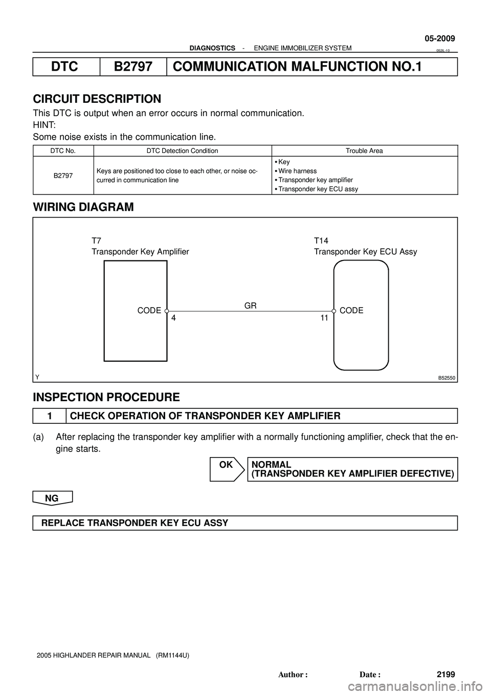
T7
Transponder Key AmplifierT14
Transponder Key ECU Assy
GR
CODE
411CODE
- DIAGNOSTICSENGINE IMMOBILIZER SYSTEM
05-2009
2199 Author�: Date�:
2005 HIGHLANDER REPAIR MANUAL (RM1144U)
DTC B2797 COMMUNICATION MALFUNCTION NO.1
CIRCUIT DESCRIPTION
This DTC is output when an error occurs in normal communication.
HINT:
Some noise exists in the communication line.
DTC No.DTC Detection ConditionTrouble Area
B2797Keys are positioned too close to each other, or noise oc-
curred in communication line
�Key
�Wire harness
�Transponder key amplifier
�Transponder key ECU assy
WIRING DIAGRAM
INSPECTION PROCEDURE
1 CHECK OPERATION OF TRANSPONDER KEY AMPLIFIER
(a) After replacing the transponder key amplifier with a normally functioning amplifier, check that the en-
gine starts.
OK NORMAL
(TRANSPONDER KEY AMPLIFIER DEFECTIVE)
NG
REPLACE TRANSPONDER KEY ECU ASSY
052IL-10
Page 1101 of 2572

INSPECTION")
B66220 YB66220 YB66229
T14
Transponder Key ECU Assy
E6
ECM Wire Harness Side
- DIAGNOSTICSENGINE IMMOBILIZER SYSTEM
05-201 1
2201 Author�: Date�:
2005 HIGHLANDER REPAIR MANUAL (RM1144U)
INSPECTION PROCEDURE
1 CHECK WIRE HARNESS (TRANSPONDER KEY ECU ASSY - ECM)
(TRANSPONDER KEY ECU ASSY OR ECM - BODY GROUND)
(a) Disconnect the T14 ECU and E6 ECM connectors.
(b) Measure the resistance between the wire harness side
connectors.
Standard:
Symbols (Terminal No.)Specified Condition
EFIO (T14-6) - IMI (E6-27)Below 1 W
EFII (T14-7) - IMO (E6-26)Below 1 W
(c) Measure the resistance between the T14 or E6 wire har-
ness side connector and the body ground.
Standard:
Symbols (Terminal No.)Specified Condition
EFIO (T14-6) or IMI (E6-27) -
Body ground10 kW or higher
EFII (T14-7) or IMO (E6-26) -
Body ground10 kW or higher
OK REPAIR OR REPLACE HARNESS AND
CONNECTOR
NG
2 CHECK OPERATION OF TRANSPONDER KEY AMPLIFIER
(a) After replacing the transponder key amplifier with a normally functioning amplifier, check that the en-
gine starts.
NG REPLACE TRANSPONDER KEY ECU ASSY
OK
NORMAL (TRANSPONDER KEY AMPLIFIER DEFECTIVE)
Page 1120 of 2572

H03352C81305H43424
Engine Room
Main Wire
Airbag
Sensor
Assy
CenterAirbag
Front
RH
Sensor
Cowl Wire
-SR+SR
Service Wire
A
B
C D E F
-SR+SR
A9
IK1
H03354C81305H43447
Engine Room
Main Wire
Airbag
Sensor
Assy
CenterAirbag
Front
RH
Sensor
Cowl Wire
-SR+SR
A
B
C D E F
IK1
- DIAGNOSTICSSUPPLEMENTAL RESTRAINT SYSTEM
05-1337
1527 Author�: Date�:
2005 HIGHLANDER REPAIR MANUAL (RM1144U)
8 CHECK ENGINE ROOM MAIN WIRE(OPEN)
(a) Disconnect the engine room main wire connector from the
cowl wire.
HINT:
Connector ºEº has already been inserted into the service wire.
(b) Measure the resistance according to the value(s) in the
table below.
Standard:
Tester connectionConditionSpecified condition
IK1-3 (+SR) -
IK1-4 (-SR)AlwaysBelow 1 W
NG REPAIR OR REPLACE ENGINE ROOM MAIN
WIRE
OK
REPAIR OR REPLACE COWL WIRE
9 CHECK ENGINE ROOM MAIN WIRE(TO B+)
(a) Turn the ignition switch to the LOCK position.
(b) Disconnect the negative (-) terminal cable from the bat-
tery, and wait for at least 90 seconds.
(c) Disconnect the engine room main wire connector from the
cowl wire.
(d) Connect the negative (-) terminal cable to the battery,
and wait for at least 2 seconds.
(e) Turn the ignition switch to the ON position.
(f) Measure the voltage according to the value(s) in the table
below.
Standard:
Tester connectionConditionSpecified condition
IK1-3 (+SR) -
Body groundIgnition switch ONBelow 1 V
IK1-4 (-SR) -
Body groundIgnition switch ONBelow 1 V
NG REPAIR OR REPLACE ENGINE ROOM MAIN
WIRE
OK
REPAIR OR REPLACE COWL WIRE
Page 1121 of 2572

H03354C81305H43447
Engine Room
Main Wire
Airbag
Sensor
Assy
CenterAirbag
Front
RH
Sensor
Cowl Wire
-SR+SR
A
B
C D E F
IK1
H03354C81305H43447
Engine Room
Main Wire
Airbag
Sensor
Assy
CenterAirbag
Front
RH
Sensor
Cowl Wire
-SR+SR
A
B
C D E F
IK1
05-1338
- DIAGNOSTICSSUPPLEMENTAL RESTRAINT SYSTEM
1528 Author�: Date�:
2005 HIGHLANDER REPAIR MANUAL (RM1144U)
10 CHECK ENGINE ROOM MAIN WIRE(TO GROUND)
(a) Disconnect the engine room main wire connector from the
cowl wire.
(b) Measure the resistance according to the value(s) in the
table below.
Standard:
Tester connectionConditionSpecified condition
IK1-3 (+SR) -
Body groundAlways1 MW or Higher
IK1-4 (-SR) -
Body groundAlways1 MW or Higher
NG REPAIR OR REPLACE ENGINE ROOM MAIN
WIRE
OK
REPAIR OR REPLACE COWL WIRE
11 CHECK ENGINE ROOM MAIN WIRE(SHORT)
(a) Disconnect the engine room main wire connector from the
cowl wire.
(b) Measure the resistance according to the value(s) in the
table below.
Standard:
Tester connectionConditionSpecified condition
IK1-3 (+SR) -
IK1-4 (-SR)Always1 MW or Higher
NG REPAIR OR REPLACE ENGINE ROOM MAIN
WIRE
OK
REPAIR OR REPLACE COWL WIRE
Page 1127 of 2572

H03352C81305H43424
Engine Room
Main Wire
Service Wire
Airbag
Sensor
Assy
Center
Airbag Sensor
Front LH
A
B C
D E FCowl Wire
-SL+SLA8
IK1
-SL+SL
H03354C81305H43447
Engine Room
Main Wire
-SL
+SLAirbag
Sensor
Assy
Center
Airbag Sensor
Front LH
A
B C D E FCowl Wire
IK1
05-1344
- DIAGNOSTICSSUPPLEMENTAL RESTRAINT SYSTEM
1534 Author�: Date�:
2005 HIGHLANDER REPAIR MANUAL (RM1144U)
8 CHECK ENGINE ROOM MAIN WIRE(OPEN)
(a) Disconnect the engine room main wire connector from the
cowl wire.
HINT:
Connector ºEº has already been inserted into the service wire.
(b) Measure the resistance according to the value(s) in the
table below.
Standard:
Tester connectionConditionSpecified condition
IK1-1 (-SL) -
IK1-2 (+SL)AlwaysBelow 1 W
NG REPAIR OR REPLACE ENGINE ROOM MAIN
WIRE
OK
REPAIR OR REPLACE COWL WIRE
9 CHECK ENGINE ROOM MAIN WIRE(TO B+)
(a) Turn the ignition switch to the LOCK position.
(b) Disconnect the negative (-) terminal cable from the bat-
tery, and wait for at least 90 seconds.
(c) Disconnect the engine room main wire connector from the
cowl wire.
(d) Connect the negative (-) terminal cable to the battery,
and wait for at least 2 seconds.
(e) Turn the ignition switch to the ON position.
(f) Measure the voltage according to the value(s) in the table
below.
Standard:
Tester connectionConditionSpecified condition
IK1-1 (-SL) -
Body groundIgnition switch ONBelow 1 V
IK1-2 (+SL) -
Body groundIgnition switch ONBelow 1 V
NG REPAIR OR REPLACE ENGINE ROOM MAIN
WIRE
OK
REPAIR OR REPLACE COWL WIRE