Page 738 of 2572
TightenFix
A52459
Paint Mark7 Links
Timing Mark
Groove Paint Mark
Timing Marks
A52460
Raise
PinHook
Push
A52461
Engine
Front
A52462
- ENGINE MECHANICALVALVE CLEARANCE (2AZ-FE)
14-13
2506 Author�: Date�:
2005 HIGHLANDER REPAIR MANUAL (RM1144U)
(4) Fix the camshaft with a wrench, then tighten the
sprocket bolt.
Torque: 54 NVm (551 kgfVcm, 40 ftVlbf)
NOTICE:
Be careful not to damage the valve lifter.
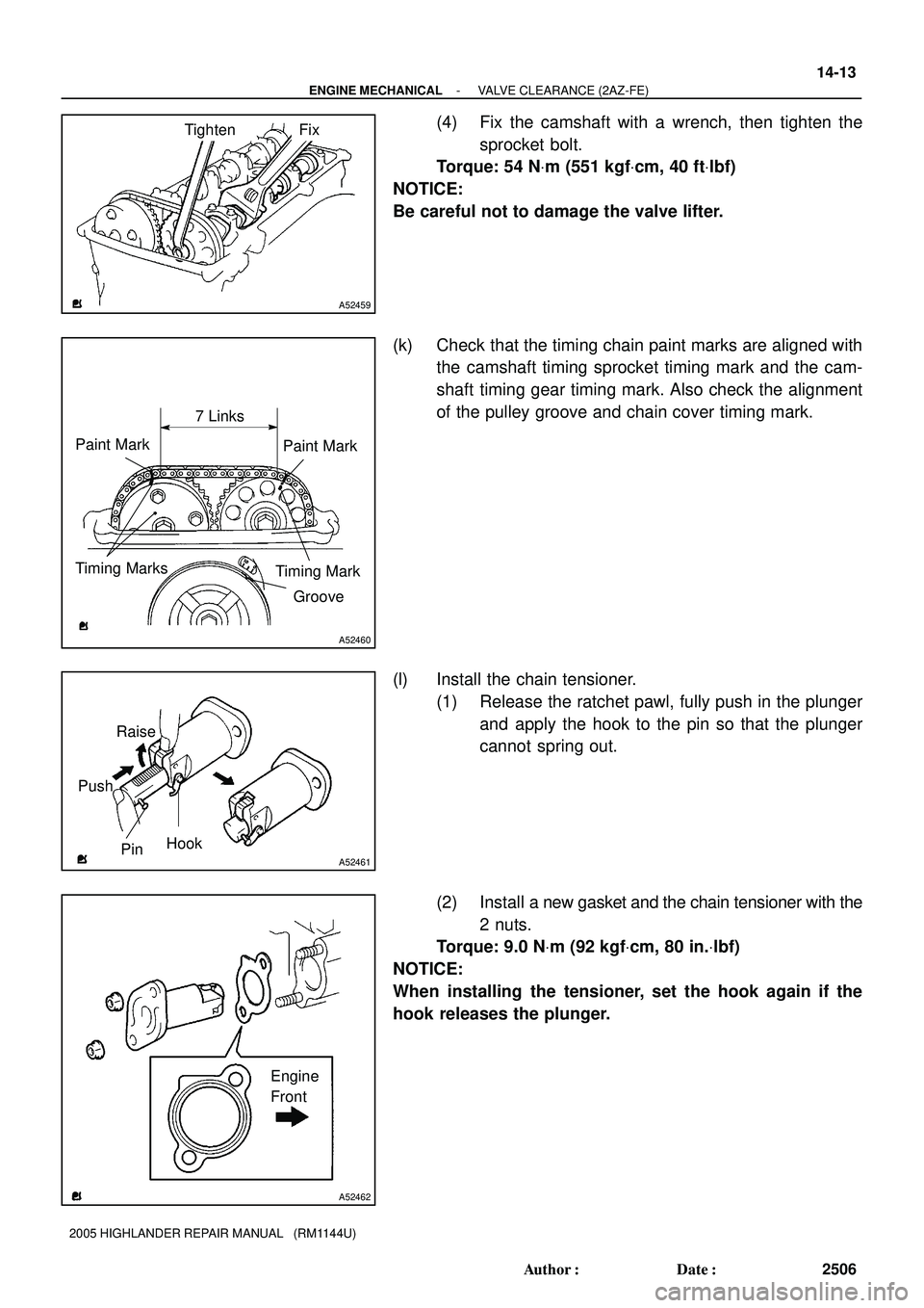
(k) Check that the timing chain paint marks are aligned with
the camshaft timing sprocket timing mark and the cam-
shaft timing gear timing mark. Also check the alignment
of the pulley groove and chain cover timing mark.
(l) Install the chain tensioner.
(1) Release the ratchet pawl, fully push in the plunger
and apply the hook to the pin so that the plunger
cannot spring out.
(2) Install a new gasket and the chain tensioner with the
2 nuts.
Torque: 9.0 NVm (92 kgfVcm, 80 in.Vlbf)
NOTICE:
When installing the tensioner, set the hook again if the
hook releases the plunger.
Page 739 of 2572

2507 Author�: Date�:
2005 HIGHLANDER REPAIR MA")
A93972
Disconnect
HookPin
Turn
A93973
Plunger
Push
Turn
Seal Packing
A53051
NutNutA61989
A
B A
A
A
A
AB 14-14
- ENGINE MECHANICALVALVE CLEARANCE (2AZ-FE)
2507 Author�: Date�:
2005 HIGHLANDER REPAIR MANUAL (RM1144U)
(3) Turn the crankshaft counterclockwise, and discon-
nect the plunger knock pin from the hook.
(4) Turn the crankshaft clockwise, and check that the
slipper is pushed by the plunger.
13. INSTALL CYLINDER HEAD COVER SUB-ASSY
(a) Remove any old packing (FIPG) material.
(b) Apply seal packing to 2 locations as shown in the illustra-
tion.
Seal packing: Part No. 08826-00080 or equivalent
NOTICE:
�Remove any oil from the contact surface.
�Install the cylinder head cover within 5 minutes after
applying seal packing.
�Do not start the engine for at least 2 hours after instal-
ling the cylinder head cover.
(c) Install the cylinder head cover with the 8 bolts and 2 nuts.
Torque:
11 NVm (112 kgfVcm, 8 ftVlbf) for nut
11 NVm (112 kgfVcm, 8 ftVlbf) for bolt A
14 NVm (143 kgfVcm, 10 ftVlbf) for bolt B
14. INSTALL SPARK PLUG
Torque: 19 NVm (194 kgfVcm, 14 ftVlbf)
15. INSTALL IGNITION COIL ASSY
Torque: 9.0 NVm (92 kgfVcm, 80 in.Vlbf)
16. INSTALL FRONT WHEEL RH
17. CHECK FOR ENGINE COOLANT LEAKS (See page 16-6)
Page 746 of 2572

S27
BRL
- DIAGNOSTICSABS WITH EBD & BA & TRAC & VSC SYSTEM
05-855
1045 Author�: Date�:
INSPECTION PROCEDURE
HINT:
When releasing the parking brake, se")
G24767
Skid Control ECU
(harness side connector)
S27
BRL
- DIAGNOSTICSABS WITH EBD & BA & TRAC & VSC SYSTEM
05-855
1045 Author�: Date�:
INSPECTION PROCEDURE
HINT:
When releasing the parking brake, set the chocks to hold the vehicle for safety.
1 CHECK BRAKE FLUID
(a) Release the parking brake pedal.
(b) Check that the brake fluid level is proper.
NG ADD BRAKE FLUID
OK
2 CHECK DTC FOR ABS
(a) Are the DTC recorded? (see page 05-765)
NO Go to step 3
YES
REPAIR CIRCUIT INDICATED BY OUTPUT CODE
3 INSPECT BRAKE WARNING LIGHT
WHEN USING HAND-HELD TESTER:
(a) Connect the hand-held tester to the DLC3.
(b) Start the engine.
(c) Select the item ºBRAKE WARN LIGHTº in the ACTIVE TEST and operate the BRAKE warning light
on the hand-held tester.
ItemVehicle Condition / Test DetailsDiagnostic Note
BRAKE WRN LIGHTTurns BRAKE warning light ON / OFFObserve combination me-
ter
(d) Check that ºONº and ºOFFº of the BRAKE warning light are indicated on the combination meter when
using the hand-held tester.
OK:
Turn the BRAKE warning light on or off in accordance with the hand-held tester.
WHEN NOT USING HAND-HELD TESTER:
(a) Turn the ignition switch off and disconnect the connector
from the skid control ECU.
(b) Ground terminal BRL of the skid control ECU.
(c) Turn the ignition switch to the ON position.
(d) Check that the brake warning light.
OK:
Turn the light on or off in accordance with the connec-
tion of terminal BRL and body ground.
NG Go to step 4
OK
REPLACE ABS & TRACTION ACTUATOR ASSY (SEE PAGE 32-37)
Page 751 of 2572

S27
WA
- DIAGNOSTICSABS WITH EBD & BA & TRAC & VSC SYSTEM
05-845
1035 Author�: Date�:
INSPECTION PROCEDURE
1 INSPECT ABS WARNING LIGHT
WHEN USING HAND")
G24767
Skid Control ECU
(harness side connector)
S27
WA
- DIAGNOSTICSABS WITH EBD & BA & TRAC & VSC SYSTEM
05-845
1035 Author�: Date�:
INSPECTION PROCEDURE
1 INSPECT ABS WARNING LIGHT
WHEN USING HAND-HELD TESTER:
(a) Connect the hand-held tester to the DLC3 and start the engine.
(b) Select the item ºABS WARN LIGHTº in the ACTIVE TEST and operate the ABS warning light on the
hand-held tester.
ItemVehicle Condition / Test DetailsDiagnostic Note
ABS WARN LIGHTTurns ABS warning light ON / OFFObserve combination me-
ter
(c) Check that ºONº and ºOFFº of the ABS warning light can be shown on the combination meter by the
hand-held tester.
OK:
Turn the ABS warning light ON or OFF in accordance with the hand-held tester.
WHEN NOT USING HAND-HELD TESTER:
(a) Turn the ignition switch off and disconnect the connector
from the skid control ECU.
(b) Ground terminal WA of the skid control ECU.
(c) Turn the ignition switch to the ON position.
(d) Check that the ABS warning light.
OK:
Turn the light ON or OFF in accordance with the con-
necting condition of terminal WA and body ground.
NG CHECK AND REPAIR ABS WARNING LIGHT
CIRCUIT
OK
Page 771 of 2572

F40566
Skid Control ECU with Actuator
2
1
1817
FL+
FL- A4
ABS Speed Sensor
Front LH
43
FR+
FR- A5
ABS Speed Sensor
Front RHS27 R-Y
LG
O
P 2
1S27
S27
S27
- DIAGNOSTICSABS WITH EBD & BA & TRAC & VSC SYSTEM
05-789
979 Author�: Date�:
WIRING DIAGRAM
INSPECTION PROCEDURE
HINT:
Start the inspection from step 1 when using the hand-held tester and start from step 3 when not using the
hand-held tester.
1 READ VALUE OF HAND-HELD TESTER(FRONT SPEED SENSOR)
(a) Connect the hand-held tester to the DLC3.
(b) Start the engine.
(c) Select the DATA LIST mode on the hand-held tester.
(d) Check that there is no difference between the speed value output from the speed sensor displayed
on the hand-held tester and the speed value displayed on the speedometer when driving the vehicle.
ItemMeasurement Item /
Range (Display)Normal Condition
WHEEL SPD FR
Wheel speed sensor (FR) reading /
min.: 0 km/h (0 MPH, max.: 326 km/h
(202 MPH)
Actual wheel speed
WHEEL SPD FL
Wheel speed sensor (FL) reading /
min.: 0 km/h (0 MPH, max.: 326 km/h
(202 MPH)
Actual wheel speed
OK:
There is almost no difference from the displayed speed value.
HINT:
There is tolerance of + 10 % in the speedometer indication.
NG Go to step 3
OK
Page 778 of 2572

W04200
Normal Signal Waveform
1 V / Division2 m/s / DivisionGND
05-796
- DIAGNOSTICSABS WITH EBD & BA & TRAC & VSC SYSTEM
986 Author�: Date�:
INSPECTION PROCEDURE
HINT:
Start the inspection from step 1 when using the hand-held tester and start from step 3 when not using the
hand-held tester.
1 READ VALUE OF HAND-HELD TESTER(REAR SPEED SENSOR)
(a) Connect the hand-held tester to the DLC3.
(b) Start the engine.
(c) Select the DATA LIST mode on the hand-held tester.
(d) Check that there is no difference between the speed value output from the speed sensor displayed
by the hand-held tester and the speed value displayed on the speedometer when driving the vehicle.
ItemMeasurement Item /
Range (Display)Normal Condition
WHEEL SPD RL
Wheel speed sensor (RL) reading /
min.: 0 km/h (0 MPH, max.: 326 km/h
(202 MPH)
Actual wheel speed
WHEEL SPD RR
Wheel speed sensor (RR) reading /
min.: 0 km/h (0 MPH, max.: 326 km/h
(202 MPH)
Actual wheel speed
OK:
There is almost no difference in the displayed speed value.
HINT:
There is tolerance of ± 10 % in the speedometer indication.
NG Go to step 3
OK
2 INSPECT SPEED SENSOR AND SENSOR ROTOR SERRATIONS
INSPECTION USING OSCILLOSCOPE
(a) Connect the oscilloscope to terminals RR+ - RR- or RL+
- RL- of the skid control ECU.
(b) Drive the vehicle at approximately 19 mph (30 km/h), and
check the signal waveform.
OK:
A waveform as shown in a figure should be output.
HINT:
�As the vehicle speed (wheel revolution speed) increases,
a cycle of the waveform narrows and the fluctuation in the
output voltage becomes greater.
�When noise is identified in the waveform on the oscillo-
scope, error signals are generated due to the speed sen-
sor rotor's scratches, looseness or foreign matter at-
tached to it.
NG Go to step 6
OK
REPLACE REAR SPEED SENSOR (SEE PAGE 32-37)
Page 788 of 2572

F40458
ABS2 FL BLOCK
05-806
- DIAGNOSTICSABS WITH EBD & BA & TRAC & VSC SYSTEM
996 Author�: Date�:
INSPECTION PROCEDURE
HINT:
Start the inspection from step 1 when using the hand-held tester and start from step 2 when not using the
hand-held tester.
1 PERFORM ACTIVE TEST BY HAND-HELD TESTER(ABS MOTOR RELAY
OPERATION)
(a) Connect the hand-held tester to the DLC3.
(b) Start the engine.
(c) Select the ACTIVE TEST mode on the hand-held tester.
(d) Check the operation sound of the ABS motor individually when operating it with the hand-held tester.
ItemVehicle Condition / Test DetailsVehicle Condition / Test Details
ABS MOT RELAYABS motor relay / ON or OFFON : Motor relay ON
OK:
The operation sound of the ABS motor should be heard.
NG Go to step 2
OK
REPLACE ABS & TRACTION ACTUATOR ASSY (SEE PAGE 32-37)
2 INSPECT FUSE(ABS2 FUSE)
(a) Remove ABS2 fuse from the FL BLOCK.
(b) Check continuity of ABS2 fuse.
Standard:
ABS No.1 fuseBelow 1W (Continuity)
NG CHECK FOR SHORT IN ALL HARNESS AND
CONNECTOR CONNECTED TO FUSE AND
REPLACE FUSE
OK
Page 794 of 2572
05-812
- DIAGNOSTICSABS WITH EBD & BA & TRAC & VSC SYSTEM
1002 Author�: Date�:
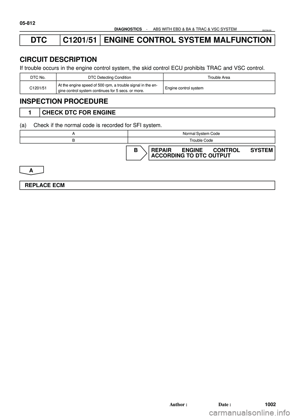
DTC C1201/51 ENGINE CONTROL SYSTEM MALFUNCTION
CIRCUIT DESCRIPTION
If trouble occurs in the engine control system, the skid control ECU prohibits TRAC and VSC control.
DTC No.DTC Detecting ConditionTrouble Area
C1201/51At the engine speed of 500 rpm, a trouble signal in the en-
gine control system continues for 5 secs. or more.Engine control system
INSPECTION PROCEDURE
1 CHECK DTC FOR ENGINE
(a) Check if the normal code is recorded for SFI system.
ANormal System Code
BTrouble Code
B REPAIR ENGINE CONTROL SYSTEM
ACCORDING TO DTC OUTPUT
A
REPLACE ECM
05CD6-06